CDMA communications system is analyzed using different antenna array ... Voice-Data System Having a Single Dominant High Data User. Joseph P. ..... Figure 1 plots the PDF of Z vs. 2. 2 ÏÏ .... Simon, M.K. and Alouni, M., âDigital Communication over ... S. Haykin, âAdaptive Filter Theory,â Third Edition, pg 565. Prentice Hall ...
CDMA Reverse Link Spatial Combining Gains: Optimal vs. MRC in a Faded Voice-Data System Having a Single Dominant High Data User Joseph P. Burke, Student Member, IEEE
James R. Zeidler, Fellow, IEEE
Department of Electrical and Computer Engineering University of California, San Diego San Diego, CA 92093-0407 also with QUALCOMM, Inc. 5775 Morehouse Drive San Diego, CA 92121
Department of Electrical and Computer Engineering University of California, San Diego San Diego, CA 92093-0407 also with SPAWAR Systems Center, D805 San Diego, CA 92152
The direct analysis of Z instead of separate analysis of the OC and MRC CINR for one high power user offers a simplified analytical treatment, additional insight into true spatial combining algorithm gain differences, and more direct mapping to final system CDMA capacity improvements [8]. Section II describes the general system model. Section III develops the CINRMRC and CINROC. The statistics of Z are developed in Section IV. Section V compares CDMA Reverse Link Monte Carlo Simulations with the developed analytical results.
Abstract-- The per user carrier-to-interference ratio (CINR) enhancement in the Reverse Link (mobile to base station) of a CDMA communications system is analyzed using different antenna array spatial combining algorithms: Optimum Combining (OC) versus Maximal Ratio Combining (MRC) in a multi-rate (combined voice and data users) multi-antenna scenario. Many low data voice users and a single dominant high data user are used to achieve a high degree of colored spatial interference in the analysis. The ratio of the CINR for OC vs. MRC is directly analyzed, i.e. Z=CINROC/CINRMRC instead of separate analysis of each CINR term: CINROC and CINRMRC with later comparison. Exact solutions are derived for the statistics of a per user CINROC/CINRMRC improvement, as a function of the high-level interference power to background noise, and is compared with CDMA Reverse Link Monte Carlo simulations.
II. SYSTEM MODEL We define a simplified multi-rate (mixed voice-data) power distribution model for the CDMA Reverse Link in this section.
I. INTRODUCTION Cdma2000-EV, WCDMA and other next generation codedivision multiple access (CDMA) systems offer voice and high data user traffic on the Forward (base station to mobile) and Reverse Link (mobile to base station). Each of these systems employs multi-rate signaling: low and high power or data rate signals that can color the background interference spatially. In a spatially uncolored or white noise environment, the OC spatial matched filter (spatial combining algorithm) performs equivalently to MRC, i.e. the same final combining weight solution for the antenna weights. However, OC combining can offer gains over MRC when the spatial noise has a high degree of spatial coloring (ratio of data users power to background noise). In [1], an analysis of one dominant high power user relative to background noise was analyzed for the OC CINR. [2] extended the results of [1] providing a comparison of OC vs. MRC while providing simulations with the number of interference terms greater than 1. [3-7] recently have further extended results analyzing standalone OC CINR with extensions to multi-high power interferes and reference to MRC to include stronger closed form solutions for CINR and in specific cases Bit Error Rate.
A. System Parameters A Rayleigh fading channel model, uncorrelated fading between antenna elements, perfect average power control, other cell interference modeled as many low data users, and perfect estimates of all parameters are assumed in the model. Our model singles out a low data user, x(t), with H uncorrelated fading across antennae noted as parameter α , a high data user, y(t), with uncorrelated fading across H antennae noted as parameter β , and a white noise term, n(t), that includes the thermal background noise plus all other low data CDMA multiple access interference (MAI) terms: H H H H (1) u (t ) = x (t )α + y (t ) β + n (t ) H where the signal u (t ) represents the received vector waveform on the 0:m-1 antenna elements in the antenna array. The equivalent white noise term on each antenna element is assumed complex Gaussian (circular Gaussian). The noise on all the antenna elements are i.i.d. with zero mean and variance equal to σ 2 , i.e. N m ≈ (0 , σ 2 ) . Therefore, the outer spatial correlation matrix of the white noise term, R n , reduces to a constant times the identity
0-7803-7206-9/01/$17.00 © 2001 IEEE
264
matrix Rn = σ 2 ⋅ Ι .
where in (7), we use vector notation that defines the angle between two vectors, over é0 , π ù , related to the two ê 2ú ë û vectors’ inner product and their respective norms as [10]: H H β Hα H cos φαH − β = (8) α β
The equivalent white noise term is H H assumed uncorrelated with x(t), y(t), α and β . The power in signal x(t) is E [x (t ) ⋅ x (t ) * ] = σ s2 and the power in signal y(t) is E [y (t ) ⋅ y (t ) * ] = σ y2 .
( )
B. Spatial Combiner The spatial combiner weights the received antenna samples in order to recover the desired signal in the presence of noise and interference. We define the low data user received waveform as H H u s (t ) = x(t )α and the interference to the desired low data H user as uH I (t ) = y (t ) β + nH (t ) (the sum of the high data user and white noise). The CINR of the low data user can then be expressed as: HH éw CINR = E ê H ê wH ë
H ⋅ us H ⋅ uI
B. OC Combining and CINROC Derivation The general equation for the OC weight that maximizes the CINR in (2) can be written as: H H (9) wopt = RI−1α where R I−1 is related to RU−1 in that R I−1 is the total received correlation matrix, RU−1 , minus the desired users correlation matrix, σ s2αHαH H . In general CINROC, using (2) and (9), is: H HH wopt R s wopt 2 HH −1 H CINROC = H H (10) H = σ S α RI α wopt R I wopt
ù HH H Rs w ú= w (2) H H 2 ú w H RI w û where the signal correlation matrix is defined as: HH HH HH (3) Rs = E u s usH = E x(t )αα H x (t )* = σ s2αα H and interference correlation matrix is defined as: HH H H (4) R I = E u I u IH = σ 2 Ι + σ y2 ββ H . HH where α is defined as the complex conjugate transpose H of α .
[
2
] [ [
The structure of the interference correlation matrix in (4) allows for a simple method to find the inverse correlation matrix via the Matrix Inversion Lemma [11]. The inverse correlation matrix is reduced to: H H −1 H H RI−1 = Rn−1 − Rn−1σ y2 β 1 + σ y2 β H Rn−1 β β H Rn−1 (11) HHH ö ββ 1 æ = 2 çΙ − 2 2 HH H ÷ ç σ è σ σ y + β β ÷ø Equation (11) in combination with (9) allows the optimal weight, wH opt , to be described as: HH H ö H ββ H α 1 æH wopt = 2 ç α − 2 2 H H H ÷ (12) σ çè σ σ y + β β ÷ø Using (12) in (10) yields the OC CINR as: 2 2 2 2 2 σ 2 α æ β sin φαH − βH + σ σ y ö÷ CINROC = S 2 ç (13) 2 2 2 ç ÷ σ + β σ σ y è ø
]
]
[
III. CINROC AND CINRMRC DERIVATIONS The CINRs for MRC and OC: CINRMRC and CINROC are developed in this section. A. MRC Combining and CINRMRC Derivation The Maximal Ratio Combining (MRC) algorithm weight vector for a specific user is defined as the ratio at each antenna element of the users desired received signal voltage to the total antenna noise power [9]. The MRC weight algorithm used here is simplified via the assumption of common antenna noise power on each antenna. The MRC combining weight is then defined as: H H (5) wMRC = α
( )
IV. Z=CINROC/CINRMRC: STATISTICS AND ANALYTICAL SOLUTIONS
The statistics of the ratio Z=CINRMRC/CINROC are derived in this section.
In general CINRMRC, using (2) and (5), is: H H HH H 2 w H Rs wMRC 2 (α α ) (6) CINRMRC = H MRC = σ H H S HH H wMRC RI wMRC α RI α We substitute (4), the desired users' interference outer spatial correlation matrix, into (6) and obtain the CINRMRC for the desired user in our system described via (1): CINRMRC =
σ S2 α σ 2 + σ y2 β
2
A. Developing the Ratio of CINROC/CINRMRC Taking the ratio of the OC CINR to the MRC CINR allows for a direct evaluation of the gain using OC versus MRC in a colored spatial interference environment. Additionally, using the ratio of CINROC/CINRMRC allows the desired users channel fading coefficient, α 2 , to be factored out
2
(
cos φαH − βH
)
]
(7)
and results in a simplified statistical analysis. We define Z to be the ratio of CINROC/CINRMRC as:
2
265
(
)
Ζ β ,φαH −βH ,σ 2 σ y2 = 2
[
( )
CINROC CINRMRC
][
( )
2 2 2 2 2 2 σ y2 β cos φαH −βH + σ σ y ⋅ β sin φαH −βH + σ σ y = 2 2 σ β + σ 2 σ y2 2
with mean zero, yield a spherical distributed channel signature. We use the independence assumption of α~ to α and
(14) 2
]
(
note that the distribution of the angle difference, f Φm φ H H α −β
in (16), is dependent upon the dimension of the underlying vectors (the physical number of antennae) with cos φ H H 2
( )
where in (14), Z is seen dependent upon β 2 , φ H H , and α −β
α −β
σ 2 σ y2 . Equation (14) can further be simplified to:
(
)
Ζ β ,φαH − βH ,σ 2 σ y2 = 1 + 2
σ ⋅ σ 2 y 2
4
distributed as a Beta function [13,6]. We define a constant, Pm, to be equal to:
( ) ( )
β cos φαH − βH sin φαH − βH 2
2
π 2
(15) 2 β + σ 2 σ y2 Noted observations on the performance difference between OC and MRC from (15) are: 1) The minimum gain ratio is always 1. 2) OC performs equivalent to MRC when the ratio of the high data users power, σ y2 , is small compared to
2
2
)
(
2
) ( )
m Φ
H H α −β
H H α −β
(17)
[
= E [B1, m −1 ⋅ (1 − B1, m −1 ⋅)] = E [B1, m −1 ] − E B12, m −1
]
(m − 1) m ⋅ (m + 1) where the rth moment of the Beta function, Bp,q, for integer valued p=1 and q=m-1 is defined in [14]. The PDF of two independent Rayleigh vectors’ angle differences, f Φm φ H H , versus a different number of α −β =
(
)
antenna elements was empirically determined using a Monte Carlo simulation (not shown here). The results yielded that as the number of antennae gets large, the angle difference inherently tends to become more orthogonal due to the higher vector space dimensionality (lower Pm for higher m). Noting comment 4 in Section IV-A, for increasing number of antennae, MRC will tend to perform closer to OC. Z is now written independent of φ H H but still dependent α −β upon β 2 , σ 2 σ y2 , and Pm:
(
)
σ y2 CINROC Ζ β , σ σ , Pm = = 1 + Ρm 2 σ β CINRMRC 2
2
2 y
β 2
4
+ σ 2 σ y2
(18)
C. CDF and PDF of Z=CINROC/CINRMRC The statistics of Z give insight into the behavior of Z versus degree of spatial coloring. The PDF and CDF of Z are developed in this section. Starting with (18) while using change in variables and solving for the root of the resulting equation, we find the CDF of Z in terms of the CDF of X: æ ö æ ö σ2 2c 2 ÷ FZ ç z , c 2 = 2 , Ρm ÷ = FX ç (19) ç ÷ ç ÷ σy − 1 + 1 + 4 ⋅ Ρ ( z − 1 ) m è ø è ø where the CDF of X is the CDF of a chi-square random variable ( X = β 2 ) with n=2m degrees of freedom (m is
α −β
(
2
0
B. Angle Distribution Between Two Channel Signatures The vector angle difference between the desired low data H user channel signature, α , and the high data user channel H signature, β , will change as a function of time due to the inherent changes in the channel and plays an important role in the gain of OC versus MRC. We seek to find Z independent of φ H H : Ζ β , σ 2 σ y2 = ò Ζ β , φαH − βH f Φm φαH −βH dφαH − βH
[ ( ) ( ) ] f (φ )dφ
Ρm = ò cos φαH − βH sin φαH − βH
the background thermal noise power σ 2 . Additionally, deep fades of the high data user will decrease the gain ratio. H 3) When the low data users channel vector, α , and H the high data users channel vector, β , are 0 degrees apart, both OC and MRC perform equivalently. This is analogous to the low data user and high data user spatially located in the same direction. H 4) When the low data users channel vector, α , and H the high data users channel vector, β , are 90 degrees apart, both OC and MRC perform equivalently. As OC seeks to find the portion of the low data users signal spatially orthogonal to the high data users signal (max CINR), when the vectors are already 90 degrees apart, the two vectors are already orthogonal, and MRC by circumstance will perform as well as OC.
π 2
)
(16)
0
We first define the normalized channel signature α and note α~ to be independent of the underlying ~ α= α
the number of antennae). We solve for the PDF of Z using Leibniz’s Rule, noting dF ( z ) , while defining the variance of each f Z (z ) = Z dz Gaussian random variable making up the chi-square
channel signature norm, α . The independence of α~ with H α is valid if α , is a m-variate spherical distribution with mean equal to zero [12]. The components of the Rayleigh fading channel signature, complex Gaussian distributed
266
distribution to be 0.5 (such that the average channel gain is one) to obtain:
) (m2−P1)! ⋅ (2c ) (z − 1)
(
2 m
f Z z , c 2 = σ 2 σ y2 , Pm =
m
2
æ1ö ⋅ç ÷ èbø
m +1
⋅
e
TABLE 1 Average Z versus c 2 = σ 2 σ y2 for Different Number of Antennae Assuming Rayleigh Faded Channels with σ X2 = 0.5
−2 c 2 b
(20)
(b + 1)
where b = −1 + 1 + 4 Pm . (z − 1) Figure 1 plots the PDF of Z vs. σ y2 σ 2 (0.5, 1.0, and 5.0) using (20). The PDF of Z is shown to be near singular for low σ y2 σ 2 (equivalent statistics for OC and MRC). Probability 10
8
σ 2y σ
6 4
σy
2
Probability 5 = 0.5
3
2
σ
2
2
= 1.0
σy
2
2
4 (a)
2
6
8
= 0.5
2
2
= 1.0
σ 2y σ
0 0
2
Linear gain of z
4 (b)
2
= 5.0
6
power to high data rate user power, is derived in this section and is useful to determine the average CINR increases using OC versus MRC. The average value of Z is found by integrating (15) over the vector angle difference, φ H H , and the fading PDF of α −β the high data user (PDF of X = β 2 ):
( )
æ σ2ö ∞2 æ 2 σ2ö Ζç m, 2 ÷ = ò ò Ζç β ,φαH − βH , 2 ÷ f Φm φαH −βH f Χm ( x ) dφαH − βH dx (21) ç σ ÷ ç σ y ÷ø y ø 0 0 è è We solve (21) using (18) while integrating over 2 X = β . Defining an average channel gain of one, we
(
)
( )
( ) ( ))
2 β , and vector angle difference, φαH − βH .
CINR samples using OC weights (9) and MRC weights (5) were generated. The ratio of the simulated values for CINROC and CINRMRC were then used to obtain simulated statistics for Z.
obtain an exact expression for the average value of Z dependent upon m and c 2 : æ m r 2 r m − 1) ç å (− 1) c (m − r )! ( 2 Ζ m, c = 1 + 2 ⋅ ç r =0 c ⋅ (m + 1)! ç m +1 2 m +1 exp c 2 ⋅ Ei 1, c 2 è + (− 1) c ∞ where Ei (n, x ) = exp(− x ⋅ t ) dt . ò1 t n
(
A. Simulation Parameters The simulation uses the same model as (1), i.e. one low data user, one high data user, and background noise. In the simulation the following additional assumptions are made: 1) The user-to-user cross-correlation properties of the PN sequences, which comprise the CDMA signals, lowers the user-to-user cross terms into the background noise floor. This assumption is used both for the on-diagonal and the off-diagonal elements of the received waveform outer spatial correlation matrix. 2) Each time index in the simulation is a completely new Rayleigh faded channel signature. Therefore, the simulation covers the entire range of fading, α 2 and
D. Average Gain of Z=CINROC/CINRMRC The average value for Z given m, the number of antenna elements, and c 2 = σ 2 σ y2 , the ratio of background noise
( )
0.16 6 ⋅ 2 − c 2 + c 4 − c6 exp c 2 ⋅ Ei 1, c 2 c2 ö 0.150 æ c 4 c 6 c8 c10 1 + 2 ⋅ çç 4 − c 2 + − + − exp(c 2 ) ⋅ Ei (1, c 2 )÷÷ c 3 6 6 6 ø è 1+
A Monte Carlo simulation of the CDMA Reverse Link was developed and run to understand the ability of the theoretical model in (22) to accurately predict the average value of Z.
8
Figure 1. PDF of Z=CINROC/CINRMRC vs. σ y2 σ 2 : a) Two antennae, b) Four antennae.
π
2
V. REVERSE LINK SIMULATIONS VERSUS THEORY AND EXPECTED CAPACITY GAINS
2
σ
1
= 5.0
2
σy
2 σ
0 0
σ
Average of Gain Ratio æ σ 2 ö CINROC Ζç c 2 = 2 ÷ = ç σ y ÷ø CINRMRC è
4
σy
4
No. Ant m
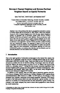
B. Reverse Link Simulations vs Theoretical Results Simulations for the average value of Z were run for 2 antennae and 4 antennae configurations versus σ y2 σ 2 .
ö ÷ ÷ (22) ÷ ø
( ) ( )
Figure 2 plots (22) and its corresponding simulated value. Figure 2 compares well with results in [2], Figures 4 and 8.
Table 1 illustrates the average value of Z, using (22), for the special cases of m=2 and 4 antennae.
267
10
1 4 Antennae
MRC
MRC
0.5
1.0
10*LOG
1
0.5 OC
(Z) 10
OC
0 -60
0.1
Simulation
1.0
-20
0
20
(b)
1 MRC
10
0.5
σy
2
σ
0
1
x
1
0.1
-20 (a)
Theory
2 Antennae
0.01
-40
0 -40
0.5 MRC
2
OC
OC
0 -60
Figure 2. Average Z=CINROC/CINRMRC for Different Number of Antennae and Degree of Spatial Coloring Assuming One High Data Rate Interference Term and All Users Rayleigh Faded (chi-square σ X2 = 0.5 ).
[4]
[5]
VI. CONCLUSION Closed form solutions were developed for the statistics of Z, the ratio of CINRs using OC versus MRC, for one dominant high data rate user. These expressions are used to define the difference in achievable (or realizable) gain of OC vs. MRC in the Reverse Link of a typical CDMA multi-rate system. The results developed for average Z allow a direct calculation for the increase in the number of low data users and overall system capacity using OC vs. MRC. The analytical results for Z were shown to compare well with simulations.
[6]
References
[11]
[3]
0
0 -40
-20
0
20
(d)
Figure 3. CDF of a Low Data Rate User’s CINR Employing OC and MRC for One High Data Rate User with σ y2 σ 2 = 1 : a) Raw CDFs for 2 antennae, b) Normalized CDFs for 2 antennae, c) Raw CDFs for 4 antennae, d) Normalized CDFs for 4 antennae.
Figures 3-b and 3-d illustrate the normalized or mean zero simulated CDFs of a low data rate user’s CINR using OC and MRC to be near equivalent. This observation supports the notion of near equivalent higher order moments or statistics of the users CINR for low values of spatial coloring (as previously illustrated in Figure 1).
[2]
-20 (c)
Figure 3 illustrates output simulated CDFs of a low data user’s CINR output for OC and MRC at σ y2 σ 2 = 1 .
[1]
-40
[7]
[8]
[9] [10]
V.M. Bogachev and I.G. Kiselev, “Optimum Combining of Signals in Space-Diversity Reception,” Telecommun. Radio Eng, Vol. 34/35. No. 10, pp. 83-85, Oct. 1980. J.H. Winters, “Optimum Combining in Digital Mobile Radio with Cochannel Interference”, IEEE Trans. Veh. Technol., Vol. VT33, Aug. 1984, pp. 144-155. B. Rao, M. Wengler, and B. Judson, “Performance Analysis and Comparison of MRC and Optimal Combining in Antenna Systems,” Proc. of the IEEE Conf. On Acoustics, Speech, and Signal Proc. Utah, May 2001.
[12] [13] [14]
268
A. Shah and A. Haimovich, “Performance Analysis of Optimum Combining in Wireless Communications with Rayleigh Fading and Cochannel Inteference,” IEEE Trans. Commun., Vol. 46, pp. 473479, Apr. 1998. E. Viller, “Performance Analysis of Optimum Combining with Multiple Interferes in Flat Rayleigh Fading,” IEEE Trans. Commun., Vol. 47, pp. 1503-1510, Oct. 1999. H. Gao, P.J. Smith, and M.V. Clark, “Theoretical Reliability of MMSE Linear Diversity Combining in Rayleigh-Fading Additive Interference Channels,” IEEE Trans. Commun., Vol. 46, pp. 666670, May 1998. Simon, M.K. and Alouni, M., “Digital Communication over Fading Channels: A Unified Approach to Performance Analysis.” Chapt. 10. John Wiley & Sons, Inc, 2000. J.P. Burke and J.R. Zeidler, “Data Throughput in a Multi-Rate CDMA Reverse Link: Comparing Optimal Spatial Combining vs. Maximal Ratio Combining.” Submitted for publication to Globecom 2001. W.C. Jakes, “Microwave Mobile Communications,” pg. 316. IEEE Press, 1974. P. Brockwell and R. Davis, “Time Series: Theory and Methods,” Second Edition, pg 42-45. Springer-Verlag, 1991. S. Haykin, “Adaptive Filter Theory,” Third Edition, pg 565. Prentice Hall, 1996. R.J. Muirhead, “Aspects of Multivariate Statistical Theory,” pg 38. John Wiley & Sons, 1982. Personal discussion with Dr. Bhaskar Rao, with the Center for Wireless Communications, Univ. of California-San Diego. N.L. Johnson, S. Kotz, and N. Balakrishnan, “Continuous Univariate Distributions,” Vol. 2. John Wiley & Sons, 1995.