INTERNATIONAL JOURNAL OF APPLIED ENGINEERING RESEARCH, DINDIGUL Volume 1, No 3, 2010 © Copyright 2010 All rights reserved Integrated Publishing Association RESEARCH ARTICLE
ISSN 09764259
CFD Modeling and Experimental Validation of Combustion in Direct Ignition Engine Fueled with Diesel Umakant V. Kongre 1 , Vivek K. Sunnapwar 2 1 Department of Mechanical Engineering, J. D. Institute of Engineering and Technology, MIDC, Lohara,Yavatmal , Maharastra,445001 India. 2 Department of Mechanical Engineering, L. T. College of Engineering, Navi Mumbai (M.S.), India
[email protected] ABSTRACT This paper describes the development and use of sub models for combustion analysis in direct injection (DI) diesel engine. In the present study the Computational Fluid dynamics (CFD) code FLUENT is used to model complex combustion phenomenon in compression ignition (CI) engine. The experiments were accomplished on single cylinder and DI engine, with full load condition at constant speed of 1500 rpm. Combustion parameters such as cylinder pressure, rate of pressure rise and heat release rate were obtained from experiment. The numerical modeling is solved by unsteady first order implicit, taking into account the effect of turbulence. For modeling turbulence Renormalization Group Theory (RNG) k ε model is used. The submodels such as droplet collision model and Taylor Analogy Breakup (TAB) model are used for spray modeling. The wallfilm model is used to assess spraywall interaction. Modeling incylinder combustion, species transport and finiterate chemistry model is used with simplified chemistry reactions. The results obtained from modeling were compared with experimental investigation. Consequences in terms of pressure, rate of pressure rise and rate of heat release are presented. The rate of pressure rise and heat release rate were calculated from pressure based statistics. The modeling outcome is discussed in detail with combustion parameters. The results presented in this paper demonstrate that, the CFD modeling can be the reliable tool for modeling combustion of internal combustion engine. Keywords: CFD, DI, combustion modeling, pressure, heat release rate, simulation. 1. Introduction Combustion research is more extensive, diverse and interdisciplinary due to powerful modeling tool like CFD. In CI engine the incylinder multiphase fluid dynamics like fuel spray, chemical reaction kinetics is influences the combustion. In past, the diesel ignition and combustion process has been modeled with several diverse models: The eddy dissipation model and its derivatives, extensions of the coherent flame model like PDF time scale models, the RIF model. Recent investigations reported the development of new and trustworthy models for combustion (Reitz R.D.et.al.; 1995, Kong S.C.et.al; 2007, Kolade B et.al.; 2004, Kong S.C et. al.; 1996, Lehtiniemi H. et.al.; 2005, Kong S.C.et. al.; 2000). The combustion model needs to consider scale fluctuations, inhomogeneities in the flow field, wall effects and turbulence level. Amongst, kε, RNG kε and twoscale models of different version were compared. To take account of flow features that are relevant to compressibility and turbulence, the RNG kε demonstrates considerable accuracy, when compared with experimental data (Rutland C.J et.al.; 2003).
508
INTERNATIONAL JOURNAL OF APPLIED ENGINEERING RESEARCH, DINDIGUL Volume 1, No 3, 2010 © Copyright 2010 All rights reserved Integrated Publishing Association RESEARCH ARTICLE
ISSN 09764259
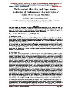
The recognized submodels for CI DI diesel combustion includes spray, droplet break up and collision, combustion and wall interaction. The combustion model gives the quantity of fuel atomized, vaporized and burned. Several studies performed with different CFD codes and methods to investigate spray pattern details of diesel injection and its effects on combustion process (Peter S. et.al.; 2000, Hergart C. et.al.; 1999, Hountalas D.T. et.al.; 2004, Philipp A. et.al. 2002, Ubertini S.; 2006, Su T.F. et.al.;1996, Watkins A.P. et.al.;1991 Bianchi G.M. et.al.; 2001, Watanabe T et.al.; 2000, Abani N.et.al.; 2008). Further, microscale phenomena of spray break up and collision having impact on overall modeling of combustion. The different break up models considering wave instabilities KH and RT mechanism predicted realistic spray (Kadocsa A. et.al.;2007). Another work performed using eddy break up model with FIRE code, modeling confirm the experimental results (Djavareshkirn M. H. et.al; 2009). In DI engine, maximum amount of fuel is sprayed over walls of combustion chamber to form the film. The importance of wall film interaction is to analyze the spray, droplet and film details. The combination of liquid film and spray film model in KIVAII code had confirm the experimental data (Stanton D. et.al.). The combustion phase was also well predicted by considering the effects of turbulent mixing on the reaction rates (Kong S.C.et.al. 2002). The application of combustion model in CI DI engines and a comparison between experimental and calculated pressure diagram had shown a good agreement (Payri F. et.al.1998). The heat released by fuel combustion is used to compute the pressure evolution in the combustion chamber. In this investigation the CFD code FLUENT is used to simulate diesel combustion Experiments were performed on CI DI engine for combustion parameters measurement. Based on pressure data and their derivatives, rate of pressure rise and heat release rate calculated. Assessment between modeling and experimental data revels that the model predicts precise results. The objective of this work is to perform modeling in CFD and to study the combustion characteristics of diesel in DI engine. 2. Geometry Development and Meshing of Computational Domain CFD codes are structured around the numerical Algorithms that can transaction with fluid flow problems. Since the computational domain is very complex, poised of four zones with different topologies, each zone has been meshed separately. In present work Geometry has been modeled and meshed in preprocessor Gambit. Figure 1 shows the computational domain of two dimensional combustion chamber geometry counting inlet and exhaust ports. Both intake ports have been meshed with same orientation in the flow direction and they are joined with a cylindrical structured mesh in the zone upstream of the valves. During the compression stroke, once the intake valve is closed, the intake port subdomains are disconnected from the calculation, so that only the combustion chamber is considered. In order to ensure grid independence and improved accuracy of the results, three calculations of the compression stroke, starting at BDC and with no valve movement (intake valve disconnected), were performed and compared to the solution of the absolute intake and compression simulation. The combustion chamber is bowlinpiston type, which having a hemispherical groove on piston top. The geometry has been modeled at its zero crank angle position at TDC as shown in figure 2. In ICE it is necessary that for obtaining realistic simulations, computation must include combustion chamber geometry with inlet and exhaust valve. The computations performed on bowlinpiston type combustion chamber reveled that,
509
INTERNATIONAL JOURNAL OF APPLIED ENGINEERING RESEARCH, DINDIGUL Volume 1, No 3, 2010 © Copyright 2010 All rights reserved Integrated Publishing Association RESEARCH ARTICLE
ISSN 09764259
instead of suction stroke at the end of compression stroke the geometry plays important role to access the combustion.
(a) (b) Figure 1 (a): Geometry of combustion chamber with valves and Figure 1 (b): Mesh structure of computational domain for model geometry. 3. Experiments Experiments were performed on a fully instrumented, single cylinder, four stroke, direct injection, at constant speed of 1500 rpm. The specification of test engine is given in the Table 1. The cylinder pressure data were averaged over 5 consecutive cycles for the same load condition. Pressure was recorded with Crank angle sensor resolution 1degree, speed 5500 rpm has TDC pulse and Piezo sensor Range 5000 PSI. For digital load measurement strain gauge sensor, range 050 Kg with eddy current dynamometer is used. Laboratory view based engine performance analysis software package is provided for on line performance evaluation. Table 1: Engine specifications Model and model
Kirloskar, TV1
Rated output (BHP/KW) Bore X Stroke (mm) Displacement volume (cc)
7 / 5.2 87.5 x 110 661
Compression Ratio
17.5:1
Fuel Injection Timing Injector opening pressure (bar)
23° BTDC (static) 200205
Injector inclination
15° to vertical axis
510
INTERNATIONAL JOURNAL OF APPLIED ENGINEERING RESEARCH, DINDIGUL Volume 1, No 3, 2010 © Copyright 2010 All rights reserved Integrated Publishing Association RESEARCH ARTICLE
ISSN 09764259
4. Model development In this paper, the problem is to be solved as unsteady first order implicit with turbulence effects considered to simulate the combustion for CI, DI engine. The numerical methodology is segregated pressurebased solution algorithm. For solving species, the discrete phase injection with species transport equation and finite rate chemistry reactions are used. The upwind scheme is employed for the discretization of the model equations. FLUENT uses a controlvolumebased technique to convert the governing equations to algebraic equations that can solve numerically. The governing equations for mass, momentum and energy equations used and appropriate initial boundary conditions were chosen for combustion analysis. 4.1. Turbulence model Turbulence is distinguished by fluctuation of velocity field. In this work well known RNG k ε model is used for modeling turbulence. The RNG k ε model was derived using a thorough statistical technique. It is analogous in form to the standard k ε model but having an advantage to include effect of swirl, which is important for ICE combustion analysis. Transport equations for the RNG ke Model is defined as,
(1) (2) In these equations, Gk characterizes the generation of turbulence kinetic energy. Gb is the generation of turbulence kinetic energy due to buoyancy. YM represents the contribution of the fluctuating dilatation in compressible turbulence. The quantities ak and aÎ are the inverse effective Prandtl numbers for k ande, respectively. Sk and Se are userdefined source terms. The model constants C1Î and C2Î in equation have values derived analytically by the RNG theory. 4.2. Spray breakup model FLUENT offers two spray breakup models, the TAB and the wave model. In the present work TAB model is used. The TAB model is based on the analogy between an oscillating and distorting droplet and a spring mass system. The distorting droplet effect is considered in the present study. The equation governing a damped, force oscillator is, F k – d = m (3) Where is the displacement of the droplet equator from its spherical position and the coefficients of this equation are taken from Taylor's analogy: ,
and
(4)
511
INTERNATIONAL JOURNAL OF APPLIED ENGINEERING RESEARCH, DINDIGUL Volume 1, No 3, 2010 © Copyright 2010 All rights reserved Integrated Publishing Association RESEARCH ARTICLE
ISSN 09764259
where and are the discrete phase and continuous phase densities, u is the relative velocity of the droplet, r is the undisturbed droplet radius, s is the droplet surface tension, and is the droplet viscosity. , and are dimensionless constants. 4.3. Droplet collision model Droplet collision model includes tracking of droplets; for estimating the number of droplet collisions and their outcomes in a computationally efficient manner. The model is based on O'Rourke's method, which assumes stochastic approximation of collisions. When two parcels of droplets collide then algorithm further establish the type of collision. Only coalescence and bouncing outcomes are measured. The probability of each outcome is calculated from the collision Weber number ( ) and fit to experimental observations. The Weber number is given as, (5) where Urel is the relative velocity between two parcels and is the arithmetic mean diameter of the two parcels. The state of the two colliding parcels is modified based on the outcome of the collision. 4.4. WallFilm Model Spraywall interaction is an important element of the mixture creation process in diesel engines. In a DI engine, fuel is injected directly into the combustion chamber, where the spray can impinge upon the piston. The modeling of the wallfilm inside a DI engine is compounded by the occurrence of carbon deposits on the surfaces of the combustion chamber. This carbon deposit soak up the liquid layer. It is understood that the carbon deposits adsorb the fuel later in the cycle. The wallfilm model in FLUENT allows a single constituent liquid drop to impinge upon a boundary surface and form a thin film. Interactions during impact with a boundary and the criteria by which the regimes are detached are based on the impact energy and the boiling temperature of the liquid. The impact energy is defined by,
(6) where r is the liquid density, Vr is the relative velocity of the particle in the frame of the wall, D is the diameter of the droplet, and s is the surface tension of the liquid. Here, dbl is a boundary layer thickness. 4.5. Combustion model The combustion model was combined with species transport and finiterate chemistry with simplified chemistry reactions to simulate the overall combustion process in a diesel engine. This approach is based on the solution of transport equations for species mass fractions. The reaction rates that emerge as source terms in the species transport equations are computed from well known Arrhenius rate expressions. A chemical kinetic mechanism from the FLUENT database is used for modeling diesel combustion. For chemical species, local mass fraction of each species, Yi and through the solution of a convection diffusion equation for
512
INTERNATIONAL JOURNAL OF APPLIED ENGINEERING RESEARCH, DINDIGUL Volume 1, No 3, 2010 © Copyright 2010 All rights reserved Integrated Publishing Association RESEARCH ARTICLE
ISSN 09764259
the i th species can be used to solve conservation equation. This conservation equation takes the following general form; (7) Where Ri is the net rate of production of species i by chemical reaction and Si is the rate of creation by addition from the dispersed phase. 5. Results and Discussion 5.1. Cylinder pressure and rate of pressure rise results Figure 2 shows modeling and experimental incylinder pressure traces operating at full load condition. The modeled cylinder pressure data shows good agreement with experimental results. The maximum pressure rise depends upon the quantity of fuel vaporized during the delay time and occurs in the state of combustion, some degrees after the beginning of combustion. Note that modeling peak pressure is 66.16 bar at 366 degree CA, and experimental peak pressure is 63.55 bar at 366 degree CA. Therefore both scale and timing of occurrence of peak pressure are precisely predicted by the model. Figure 3 shows modeling and experimental rate of cylinder pressure rise which is calculated by first order derivative of cylinder pressure with crank angle. The rate of pressure rise trace reconfirms the peak pressure history obtained from pressure and crank angle diagram.
Figure 2: comparisons between modeling and experimental pressure diagram.
513
INTERNATIONAL JOURNAL OF APPLIED ENGINEERING RESEARCH, DINDIGUL Volume 1, No 3, 2010 © Copyright 2010 All rights reserved Integrated Publishing Association RESEARCH ARTICLE
ISSN 09764259
Figure 3: Comparison between modeling and experimental rate of pressure rise diagram. 5.2. Heat release rate results The observed cylinder pressure profiles reflect the effect of incylinder heat release rate. The heat release rate is determined from pressure data. Figure 4 compares heat release rates computed from modeling and experimental pressure traces. The heat release rate decreases from the start of injection to the start of combustion which is ignition delay period because of the fuel evaporation occurring during this period. The first peak due to premixed combustion strongly depends on the amount of fuel that the prepared for combustion during the ignition delay period. The second peak due to diffusion combustion is controlled by the fuelair mixing rate. Diffusion combustion continues until combustion is completed. Note that, the peak modeling heat release rate is 79.01 J/ degree where as experimental peak heat release rate is 77.34 J/ degree at 364 degree CA.
Figure 4: Comparison between modeling and experimental heat release rate diagram. 514
INTERNATIONAL JOURNAL OF APPLIED ENGINEERING RESEARCH, DINDIGUL Volume 1, No 3, 2010 © Copyright 2010 All rights reserved Integrated Publishing Association RESEARCH ARTICLE
ISSN 09764259
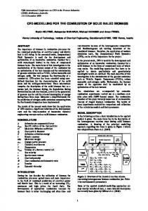
Figure 5(a,b), illustrates the instant for counters of mole fraction diesel fuel at 360 0 and 362 0 crank angle respectively. It can be seen that nearly all the liquid fuel has vapourized prior to the onset of combustion. Note that the mixture conditions are same before ignition occours since the same turbulence and spray model pridicts precise results.
(a)
(b)
Figure 5 (a), (b): countors of mole fraction diesel fuel at 360 0 and 362 0 crank angle respectively. 6. Conclusion The CFD code FLUENT has been used to simulate the combustion characteristics of direct injection diesel engine. The model also integrated with submodels includes, spray, droplet collision, wall film and combustion model with species transport and finite rate chemistry. The bowlinpiston combustion geometry was used for model construction. In this study RNG k ε model is implemented to confine incylinder turbulence. Simulated results including the incylinder pressure, rate of pressure rise and heat release rate profiles have been analyzed. A good agreement between the modeling and experimental data ensures the accuracy of the numerical predictions collected with this work. Including peak values of in cylinder pressure, rate of pressure rise and heat release rate are shown good agreement between modeling and measured data. The comparison revels that the present model manages to predict the combustion characteristics quite well. The results reported in this paper illustrate that the numerical simulation can be one of the most powerful and beneficial tool to compute the essential features of combustion parameters for ICE development, optimization and performance analysis.
515
INTERNATIONAL JOURNAL OF APPLIED ENGINEERING RESEARCH, DINDIGUL Volume 1, No 3, 2010 © Copyright 2010 All rights reserved Integrated Publishing Association RESEARCH ARTICLE
ISSN 09764259
Acknowledgement Authors also thank J. D. Institute of Engineering and Technology, Yavatmal (India) and S.S.G.M. College of Engineering, Shegaon (India), for extending all the necessary assistance to carry out this work. References 1. Abani N., Munnanur A., Reitz R. D., 2008, “Reduction of numerical parameter dependencies in diesel spray models”. Journal of engineering for Gas Turbines and Power, ASME, vol.130, 0328091 0328099. 2. Bianchi G.M., Pelloni P., Corcione F.E., Allocca L., Luppino F., 2001,”Modeling Atomization of high pressure diesel sprays”, Journal of engineering for Gas Turbines and Power, ASME, vol.123,pp 419427. 3. Djavareshkirn M. H. and Ghasemi A., 2009, “ Invistigatation of jet breakup process in diesel engine spray modeling”, Journal of Applied Sciences, Vol. 9, no.11, pp 20782087. 4. Hergart C., Barths H. and Peters N., 1999, “Modeling the combustion in a smallbore diesel engine using a method based on Representative Interactive Flamelets ”. SAE, vol.1, pp 4555. 5. Hountalas D.T., Kouremenos D.A., Mavropoulos G.C., Binder K.B. and Schwarz V., 2004, “Multizone combustion modeling as a tool for DI diesel engine development Application for the effect of injection pressure”. SAE, vol.1, 2004010115. 6. Kadocsa A., Tatschl R. and Kristof G., 2007, “ Analysis of spray evolution in internal combustion engines using numerical simulation”. Journal of Computational and Applied Mechanics, Vol. no. 8, pp 85100. 7. Kolade B., Thomas M., Kong S.C., 2004, “Coupled 1D/3D analysis of fuel injection and diesel engine combustion”, SAE International, vol.1, 110. 8. Kong S.C, Han Z., and Reitz R.D,1996, “The development and application of a diesel ignition and combustion model for multidimensional engine simulation”. SAE, 950278,. 9. Kong S.C., Kim H., Reitz R. D., Kim Y., 2007, “Comparision of diesel PCCI combustion simulation using a representative interactive flamelet model and direct integration of CFD with detailed chemistry”.Transactions of ASME, vol.129, pp 252 260. 10. Kong S.C, Reitz R. D., 2002, “Application of detailed chemistry and CFD for predicting direct injection HCCI engine combustion and emissions”, Proccedings of the combustion institute, vol.29, pp 663669.
516
INTERNATIONAL JOURNAL OF APPLIED ENGINEERING RESEARCH, DINDIGUL Volume 1, No 3, 2010 © Copyright 2010 All rights reserved Integrated Publishing Association RESEARCH ARTICLE
ISSN 09764259
11. Kong S.C., Senecal P.K. and Reitz R. D., 2000, “Developments in spray modeling in diesel and DirectInjection Gasoline engines”. Combustion and flame, vol. 121, pp 453470. 12. Lehtiniemi H., Fabian M., Balthasar M. and Magnusson I., 2005, “Modelling diesel engine combustion with detailed chemistry using a progress variable approach”, SAE, Vol.1. 13. Peter S., Atreya A. and Bryzik W., 2000, “Development of a shear layer ignition model for application to directinjection diesel engines”. Combustion and flame, vol. 121, pp 453470. 14. Philipp A., lang O., Schutz R. and Weng V., 2002 “CFD simulation of diesel injection and combustion ”, SAE, 2002010945. 15. Payri F. and Benajes J., F.V., 1998, “A phenomenological combustion model for direct injection, compression ignition engines”, Appl. Math. Modelling,Butterworth, vol.12, pp 293304. 16. Reitz R.D. and Rootland C.J., 1995, “Development and testing of diesel engine CFD model”. Prog. Combust. Sci., vol.21, pp 173196. 17. Rutland C.J., Ayoub N., Han Z., Hampson G., Kong S.C., Mather D., Montgomery D., Musculus M., Patterson M., Pierpont D., Ricart L., Stephenson P. and Reitz R.D., 2003, “Diesel Engine model development and experiments”. SAE, 16881704. 18. Stanton D. and Rutland C., “Modeling fuel film formation and wall interactions in diesel engines ”. SAE , paper no. 960628. 19. Su T.F., Patterson M.A., Reitz R.D., Farrell P.V. , 1996, “Experimental and numerical studies of high pressure multiple injection sprays”. SAE, , pp 12811292. 20. Ubertini S., 2006,”Injection pressure functions model applied to a multidimensional code for diesel engines simulation”, Transactions of the ASME, vol.128, pp 694701. 21. Watanabe T., Daidoji S., Keshav S. V, 2000, “Relationship between visible spray observations and DI diesel engine performance”. Transaction of the ASME, vol.122, 596602. 22. Watkins A.P., Khaleghi H., 1991, “Modeling spray phenomena in direct injection diesel engines”, IMechE, C433/008, pp 131141.
517