Available online at www.sciencedirect.com
ScienceDirect Energy Procedia 112 (2017) 240 – 251
Sustainable Solutions for Energy and Environment, EENVIRO 2016, 26-28 October 2016, Bucharest, Romania
CFD modelling of flow interaction in the breathing zone of a virtual thermal manikin Martin Ivanova*, Sergey Mijorskia a
Technical University of Sofia, FPEPM, Department: ”Hydroaerodynamics and Hydraulic Machines”, Sofia 1000, Bulgaria
Abstract The presented work partly reveals the development stage of a Virtual Thermal Manikin (VTM), equipped with additional breathing functionality. The methods used are based on Computational Fluid Dynamics (CFD) flow simulations and analysis. Real thermal manikins, as well as the VTMs, represent modern, highly complex tools for assessment of the occupants’ thermal comfort, as well as for analyses of indoor air quality in real or virtual enclosed environment. Also, real thermal manikins can be equipped with auxiliary devices that mimic human activities such as breathing, sweating, sneezing, coughing and others. Recent research indicates the development of an advanced compact pneumatic system, designed for implementation in the thermal manikin, capable of simulating the breathing related processes in humans. That is why the development of supplementary functionalities of the VTMs is considered as an important factor in the described research area. Thus, the presented case study reveals CFD based model of human body, with steady state breathing phases simulating the real human breathing processes. The results considering the flow interaction in the breathing zone showed good visual illustration and representation of the real physical processes. © 2017 2017Published The Authors. Published by Elsevier Ltd. © by Elsevier Ltd. This is an open access article under the CC BY-NC-ND license Peer-review under responsibility of the organizing committee of the international conference on Sustainable Solutions for Energy (http://creativecommons.org/licenses/by-nc-nd/4.0/). 2016. and Environment Peer-review under responsibility of the organizing committee of the international conference on Sustainable Solutions for Energy and Environment 2016 Keywords: Computational Fluid Dynamics, Indoor Environment, Indoor Air Quality, Virtual Thermal Manikins, Experimental Studies, Breathing Cycle
* Corresponding author. Tel.: +359-893-69-07-80 E-mail address:
[email protected]
1876-6102 © 2017 Published by Elsevier Ltd. This is an open access article under the CC BY-NC-ND license (http://creativecommons.org/licenses/by-nc-nd/4.0/). Peer-review under responsibility of the organizing committee of the international conference on Sustainable Solutions for Energy and Environment 2016 doi:10.1016/j.egypro.2017.03.1093
Martin Ivanov and Sergey Mijorski / Energy Procedia 112 (2017) 240 – 251
1. Introduction The main function of the human respiratory (breathing) system is to get oxygen into the human body and to take out waste gases. The function itself is called “respiration” (breathing), and it is a vital function of all living organisms, including human beings. Breathing is considered to be the movement of air into and out of the lungs. A healthy adult human being normally breathe 10 to 15 times per minute, at low activity level or during relaxation. Also, about 6 x 10⁻⁴ m3 of air is exchanged between the lungs and the environment, during one normal breathing cycle [1]. At the end, this corresponds to inhalation and exhalation of more than 12.9 m 3 of air per day. Consequently, the inhaled indoor air contains a wide variety of organic and inorganic compounds, which normally are not present in the outdoor air. The biggest part of them is considered as pollutants, emitted by different indoor sources, like: building materials, furniture and textile materials, TV sets and other domestic electronic appliances, cleaning agents, cooking and other home activities, heating with wood and fossil fuels, indoor plants, cigarette smoke, as well as the occupants themselves and their pets. The long time exposure to these pollutants and the significant amount of inhaled/exhaled air could develop a serious risk for the occupant’s health, comfort, productivity, and performance. All the mentioned facts contribute to the recent development of different experimental and numerical technologies for indoor air quality and thermal comfort assessment. The thermal manikins have an important role in this area, because they represent accurate models of the human body, and are able to simulate different metabolic rates as well as some human activities such as breathing, sweating, sneezing, coughing and others [2, 3, 4]. They are used to study the free convection flows in different conditions, without unnecessary exposure risk to the human occupants themselves [5, 6]. But still, the experimental studies with real thermal manikins are inflexible, cost and time consuming, requiring highly specialized labor. That is why the use of VTMs, especially for environmental design and parameters prediction, is considered as an appropriate alternative. The development of VTMs models has a lot of challenges, and basically is not an easy task, due to the diversity of thermal and flow parameters, which has to be accounted for. The development goes even more complicated when breathing functionality has to be added to the model. Milestones of the design process include the following: x The surface boundary layer, which should include the conjugate heat transfer and sweat characteristics in transient conditions, for more accurate representation of real human body surface. The study of Yang [7], has detailed both processes for VTM. x The high level of the transient character, the complexity of the aerodynamics of the generated breathing flow and the corresponding air chemical components and contaminations. Detailed work in this direction is presented in Gupta [8]. x The high complexity of the nasal valve geometrical characteristics, as well as the individual physiology and the corresponding flow resistance. Detailed analysis is presented in Nigro [9]. x In addition to all the above, the modelling of actual human body thermal mass, core temperature and fluctuation of the surface temperature could generate significant modeling complexity. Probably the most popular model accounting the thermal properties of the human body is still the IESD-Fiala model, developed in 1998 by Dr. Dusan Fiala [10]. It is a multi-segmental, multi-layered representation of the human body with spatial subdivisions which includes a detailed representation of the anatomic, thermo-physical and thermo-physiological properties of the human body [11]. His model concerns the heat transfer processes that occur inside the human body, like the blood circulation, metabolic heat generation etc. It also concerns surface processes, like free and forced surface convection, radiation, skin moisture evaporation, etc. x There also exist certain requirements that need to be addressed when VTM modelling is performed. Such requirements are proposed and described by Nilsson [12] in his work, where the development of computer manikins is described. Additionally, there are proposed CFD benchmark tests for manikin comfort level assessment. x In recent years, VTM studies have moved forward by including breathing functionalities. It is presented partly in the work of Xiangdong [13]. The study concerns the air flow patterns in different manikin’s legs positions, during exposure to diverse outdoor wind conditions. In the study, different model setups are visualized by particle tracking method. Also, experimental data is used for validation of the resultant inhale flow patterns.
241
242
Martin Ivanov and Sergey Mijorski / Energy Procedia 112 (2017) 240 – 251
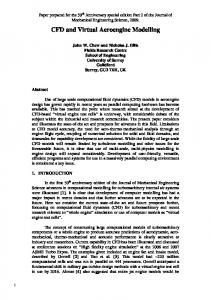
The mentioned studies suggest that breathing function is still rarely modeled, especially the exhalation/inhalation process, and more efforts are placed in the thermal functionality simulation. There is a need for additional numerical study for clarification of the breathing functionality design in the VTMs development. That is why the interaction between exhalation and inhalation driven flows with free convective flow from the buoyancy driven forces, is of a special interest in the presented paper. The authors suggest a case study of the interaction between the breathing flow and the free convection flow from the heated manikin’s surface for two steady state breathing phases, under controlled room conditions. The steady state phases are considered as Inhale phase and Exhale phase. In order to define the baseline conditions for the study, a free convection driven flow with no breathing interaction is modelled as well. These three cases will provide comprehensive analyses of the processes, occurring in the different breathing phases, and will significantly help in the further implementation of breathing functionality in the VTMs. 2. Objective and tasks of the presented study The global objective is to analyze the breathing flow interaction with the free convection flow around virtual breathing thermal manikin. Based on the global objective, the following tasks are defined: x To construct a simplified 3D model of the standard nasal geometry. x To construct VTM model with different breathing phases functionality, based on steady state CFD techniques. x To investigate and compare the flow patterns in the VTM’s breathing zone under three different phases, (free convection flow, inhale phase and exhale phase). x 3.3D geometry modelling of the manikin The comprehensive 3D female manikin was remodeled and adapted for the purpose of the study. It has an approximate surface area of 1.8 m2 and height of 1.65 m. The nasal valve opening was constructed according to the study of [14, 2]. As shown in Fig.1, the opening nasal area was 7.3 x 10 -5 m2. The normal to the nasal opening was specified to 45 degrees from the vertical body axis. Additionally, exhaust walls from the nasal valve to the nose end were inclined to 15 degrees according to [14, 2]. Also for the purpose of the study, a rectangular shaped room was built to bound the virtual thermal manikin. With gross dimensions of 4 x 4 meters and height of 3 meters, there was only one opening specified at the ceiling level with an area of 0.08 m2. As the aim of the study was to model not mechanically ventilated space under equilibrium conditions, there were no HVAC components added to the model. The manikin was placed in the center of the room and in order to reduce the computational load, a symmetry plane was introduced through the central line splitting the space into two completely identical sections.
Fig. 1. 3D model and nasal valve geometry details
Martin Ivanov and Sergey Mijorski / Energy Procedia 112 (2017) 240 – 251
4. Numerical discretization The computational domain of the room was discretized with snappyHexMesh utility [15], part of an ENGYS® (www.engys.com) enhanced version of the CFD code OpenFoam® (www.openfoam.com). The numerical grid was generated with totally of 1 140 000 poly-mesh control volume elements. A visualization of the mesh is illustrated in Fig.2. The base cell size was defined to 4 x 10⁻² m and in order to capture the nasal valve geometrical features the maximum level of cells refinement reached to 6.25 x 10 -4 m. The computational mesh parameters where selected based on the authors’ experience. The presented work is considered as a preliminary assessment of the flow characteristics around the virtual thermal manikin. A further detailed assessment will be made, as a part of breathing manikin design, including a study for grid convergence, based on the Richardson extrapolation method (or others) and a detailed analysis of the y+ values of the manikin surfaces. Additionally, the current mesh is well refined at the surface layer of the manikin, with a first layer height of 6.25 x 10 -4 m. Further details for the type of the elements included in the poly-mesh are given in Table 1. Table 1. Poly-mesh details. Type of the elements
[%]
hexahedral
94
polyhedral
3
prisms
2
wedges