Changes in soil structure caused by the installation of time domain refiectometry probes and their influence on the measurement of soil moisture. A. Rothe, ⢠W.
WATER RESOURCES RESEARCH, VOL. 33, NO. 7, PAGES 1585-1593, JULY 1997
Changes in soil structure caused by the installation of time domain refiectometry probes and their influence on the measurement
of soil moisture
A. Rothe,• W. Weis,• K. Kreutzer,• D. Matthies,2 U. Hess,3 and B. Ansorge4 Abstract. The time domain reflectometrytechniquefor measuringthe volumetric soil water contentis highly sensitiveto installationeffectsbecausethe samplingvolume is more heavilyweightedcloseto the transmissionline elements.To investigatechangesin soil structurecausedby the installationand its influenceon the measurement,field and laboratoryexperimentscoveringdifferentprobe dimensions,soil types,and installation techniqueswere performed. The resultsindicate that merely pushingthe probesinto the
soilentailsa significant reduction of themeasured watercontentup to 0.10cm3/cm 3.The effectis strongestcloseto saturationsincethe large pores are affectedmost.The degree of compressiondifferedstronglyaccordingto the varyingcompressibility of the investigatedsoils.It was smallerfor the smallerprobe indicatinga more favorable relationshipbetweensamplingvolume and compression. The compressioneffectcouldbe minimizedusinga drill to removethe soil for the probes.X ray-computedtomography was usedto visualizethe installationeffectsand to measurethe densitydistribution aroundthe probes. with distance from the transmission
Introduction
Time domain reflectometry(TDR) is a method used to determinethe water contentof soil. TDR relies on the propagationvelocityof a guided electromagneticwave in order to determinethe apparentrelative dielectricpermittivityof soil, which is highly correlated to the volumetricwater content of the soil. Originating from cable testers,the use of TDR for measuringsoil water contentwas introducedin the late 1970s [DavisandAnnan, 1977;Toppet al., 1980].Becauseof technical improvementsit hasbecomea standardmeasurementtechnique. In the last few years,numerousarticleshavebeen compiled on the technical principle and impulse processing [Heimovaara,1994;Yanukaet al., 1988], on the calibrationof dielectricpermittivityand soilwater content[Dirksenand Dasberg,1993;Roth et al., 1990],and on the designof the probes [Zegelinet al., 1989; Whalley,1993;Selkeret al., 1993]. Becauseof the technicalprinciplethe eletromagneticenergy density in the plane perpendicularto the transmissionline elementsis not spatiallyuniform;that is, the soilvolume measured effectivelyis relatively small and dependsboth on the design of the probes and on the media. Even if the exact volume measuredis not yet known, empirical investigations [Bakerand Lascano,1989;Zegelinet al., 1992] and theoretical considerations [Ferr• et al., 1996;Knight,1992] agreethat the sensitivityperpendicularto the probesdecreases exponentially •Department of SoilScience, University of Munich,Freising,Germany.
2Department of ForestWorkScience andAppliedInformatics, Uni-
line elements.
Annular
air
gapshave a strongereffectthan annularwater gaps[Annan, 1977;Ferr• et al., 1996]. Severalauthorspoint out that the installationof the probes mustbe performedvery carefully[Zegelinet al., 1992]. However,anyinstallationof TDR probeswill changethe soil structure to a certain extent and may influencethe measurement significantly. Usually,the probesare pushedinto the soilwithout the drill exceptinvestigations with probesof a diameter >10 mm [Topp and Davis, 1985]. Soil material equal to the volumeof the probe is dislocatedand compressed. This might be of minor importancein homogeneous materialsbeingused for most methodologicalinvestigations.In naturally aggregatedsoils,however,changesof pore volume and pore distribution will influence soil water characteristics[Archerand Smith, 1972] and consequentlyTDR measurements.While Toppand Davis [1985] found that direct installationof small probes(rod diameter 10 •m and 3-10 •m. On the basisof our results,
about0.06cm3/cm 3 at 10cmdepth.Bothlaboratory andfield
poreswith a diameter 10 •m was significantlylower for 20 cm and even more so for 40 cm depth.Poresfrom 3 to 10/xm in diameterare lessaffectedthan the pores> 10 •m, especiallyat 10 and 20 cm depth.At 40 and 75 cm depth the reductionof poresfrom 3 to 10 •m is comparable to the reductionof those > 10 •m.
Table
3.
Calculated
Reduction
of Pore Volume
Simultaneous Field Measurement
for Different
The resultsindicatea reductionof pores> 10 •m for P3Z of
Pore Size Classes
Field Soil-Water Characteristics
LaboratoryInvestigations
Sp >
Horizon,cm
Sp> 10
Sp= 3-10
10
Sp= 3-10
Sp> 10
Sp> 3-10
Sp> 10
Sp= 3-10
Probe type
P3Z
P3Z
P3Z
P3Z
P3Z
P3Z
P2
P2
10 20 40 75
0.056
0.026
0.059 0.038 0.012
0.030 0.020 0.008
0.065 0.048 0.017
0.029 0.016 0.014
0.026 0.027 0.024 0.029
0.011 0.009 0.020 0.022
Porevolume isin cm3/cm3; Spistheporesizein •m.
1592
ROTHE
ET AL.'
INSTALLATION
OF TIME
0,07 ,
a. ......... {...
0,06
---•--
pores >1OHm
A-..-poresfrom3 to 10 pm ,
DOMAIN
homogeneousparticle size distributionthe installationof the probes may even enlarge the pore space around them. Stacheder[1996]reportssuchan effect,whichwas highestin glassbeads (diameter 450 /.rm). The overestimationof the water
content
with
the TDR
method
at saturation
was 0.05
cm3/cm 3. Normally,the compressibility of soilincreases with '
E
PROBES
,
0,05 .... ;.,
_= 0,04 o
REFLECTOMETRY
>
'
increasing water content. The conclusion to install TDR probesat low water contentshasother drawbacks.In dry soils the increasedfriction requiresa high mechanicalforce to installthe probe.Hence the installationproceduretendsto cre-
...... • ..4....
,
o
...... i........
o. 0,03
ate cracks around
the rods. Since a classification
for soils ac-
o
•
cordingto their susceptibility for compression is still lacking,
0,02
,
................
.... •...........................•....
0,01
0
1,3
i
i
1,4
1,5
1,6
1,7
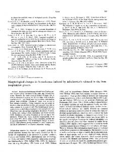
Figure 8. Relationshipbetweenbulk densityand calculated reduction of pore volume by P3Z probesfor two pore size classes.
Usingthe smallertwo-wireprobe,P2, no differencebetween horizonswas apparent.Since both accuracyand precisionof thisprobe are lower, anyeffectmightbe within the varianceof the measurements. The calculatedreductionof porevolumeat 10 and20 cm depthis abouthalf of the reductioncalculatedfor P3Z for bothpore sizeclasses; at 40 cmit is similarto P3Z. The total reductionof pore spacefor P3Z and normal installation
wasin therangeof 0.09cm3/cm 3 at 10cm,0.05cm3/cm 3 at 20 cm,and0.025cm3/cm 3 at 40 cmdepth.Thiscorresponds with the findingsof Delta T DevicesLtd. [1995],who claim an underestimationof the TDR valuesof 0.1 cm3/cm3 under most soil conditions.
The CT imagesalso indicate small changesof soil structure causedby drill installation.The comparisonbetweenhighest water contents measured
with the TDR
method
and the total
pore spacemeasuredwith the pycnometermethod givesevidencethat theseeffectsmay be of minor importance.Even for the susceptible soilsat 10 and 20 cm depththe maximalwater contentmeasuredmatchedthe rangeof total porevolume.For conventional installation, however, the water content at satu-
of different
soils remains diffi-
cult. The texture, the bulk density,and the actual moisture content could be consideredfor a rough evaluation of the susceptibility. It must be pointed out that the reductionof pore volume mentioned
bulkdensity cm3/cm3
unsuitable
the assessment of the behavior
above is a calculated
one. It is based
on TDR
measurementsand will be significantlyinfluencedby the nonlinear weightingof sensitivity.Even if the dimensionof the probesis identical,the spatialweightingof sensitivityis influencedby the distanceof the transmission line elements[Knight, 1992] and by the coating[Ferr• et al., 1996]. The closerthe electromagneticfield is concentrated around the rods, the higher the calculatedreductionwill be for an identical real compression. Ferr• et al. [1996] recently showedthat PVC coatinginfluencesthe spatialaveragingin both the axial and transverseplanes.Coated rods are more sensitiveunder conditionsof low water content leading to an underestimationof the averagewater content, if water content varies along the rods.Sincelarge spatialvariationsof water contentoccurred neither in laboratorynor in field experiments,significanteffectsof the PVC coatingon the resultscan be excluded.The nonlinearspatialweightingperpendicularto the probesis inherent to the TDR technique.Thus the effect of installation will qualitativelyapplyto all TDR designs.Empirical experimentsof Stacheder [1996]andAnsorge[1994]with the TRIME systemindicated an exponentialdecreasein sensitivityfrom the surfaceof the probes,andthe sampledsoilhasan areawith a radius which equals the distancebetween the rods. Topp [1987]andBakerand Lascano[1989]reportedsimilardimensionsfor noncoatedprobes. As alreadyreportedby Zegelinet al. [1992],the probe sensitivityis proportionalwith probewire diameter.The sampling volumeis greaterfor the larger probe, P3Z, but also the installationeffectincreaseswith the diameterof the probe.The resultsindicatethat the relationshipbetweenthe zone influencedby installationand soilsampledwith the TDR measurement was more favorable for the smaller probes. Another explanationfor the strongerreductionmeasuredwith P3Z mightbe the greatersensitivityof the centerwire comparedto the two-wireprobe,P2 [Whalley,1993].The conclusionto use verysmallprobesin orderto avoidinstallationeffectshasother drawbacks.The processingof the signalbecomesmore complicated[Heimovaara,1993],andin heterogeneous soilsa large numberof replicationsis necessary to ensurea representative
ration measuredwith TDR was out of this range in both laboratory and field measurements,although the variability in pore volume is high in thesehorizons. The resultsfor P3Z corroboratewith the physicalproperties of the soil(Figure8). The soilat 10 cm depthis relativelyloose and has a high proportionof pores >10/.rm. It is highlysusceptibleto compression. Becauseof the higherdensityat 20 cm depth the compressionis lesspronounced.Although the texture is very similar, the reduction of pore volume is significantlylower at 40 cm depththan at 10 and 20 cm. This horizon is very denseand has a relativelysmall amountof pores >10 •m. The observedreduction of hysteresisafter conventional installationcorresponds well with the fact that the hysteresis value. effect is lesspronouncedin compressedsoils.Of course,the effectof compression will stronglydependon the soiltype and Conclusions on moisture conditionsduring the installation.In less compressiblesoils(in our casefound at 40 and 75 cm depth) the Changesof soil structureand compressionof soil material influenceon the measurementwill be within the accuracyof causedby the installationof TDR probesmay have a signifithe TDR technique.In soilswith a coarsesandtexture and a canteffecton the measurementof soilmoisture.The degreeof
ROTHE
ET AL.: INSTALLATION
OF TIME
the effectdependsmainly on probe type, susceptibilityof the soil, and on actualmoistureconditions.The effectis strongest closeto saturationand lessstrikingbelow field capacity.For probeswith a large rod (diameter >6 mm) it is necessaryto removethe soilin advancewhenusedin compressible soilsand at high soil water contents.In order to avoid air gaps the diameter of the drilling hole shouldbe about 1 mm smaller than the rod itself. Installationis performedbestunder medium-moistureconditions(at field capacityto about -100 kPa). For smallerprobesit is technicallyvery difficultto removethe soil accurately,taking into accountthat small gapscausedby drilling may have a strongereffect than compression.Since drill installation is time-consumingand requires technical training,it may be appropriateto useconventionalinstallation techniquesin manycases(e.g., lesssusceptiblesoil typesand nonpermanentmeasurements) despitethe greatererrors.Today,manydifferentprobedesignsfor differentapplicationsare available.In order to choosethe optimaldesignfor a certain applicationit is necessaryto considerthe influenceof changes in soil structureon the measurementas well as many other aspectslike signalinterpretationand spatial resolution.Further researchis neededto quantifysuchchangesfor different soil conditions,TDR systems,and probe designs.
DOMAIN
REFLECTOMETRY
PROBES
1593
tometrywaveforms,1, Measurements of the complexdielectricpermittivity of soils,WaterResour.Res.,30(2), 189-199, 1994. IMKO, TRIME, productguide,IMKO GmbH, Ettlingen, Germany, 1996.
Klute, A. (Ed.), Methodsof SoilAnalysis,vol. 1, Physicaland MineralagicalMethods,Am. Soc.of Agron., Madison,Wis., 1986. Knight, J. H., Sensitivityof time domain reflectometrymeasurements to lateralvariationsin soilwater content,WaterResour.Res.,28(9), 2345-2352, 1992.
Kreutzer,K., A. Goettlein,P. Proebstle,and M. Zuleger, Hoeglwald research:Objective,experimentaldesign,baseinformation(in Germany),Farstwiss. Farsch.,39, 11-21, 1991. Petrovic,A., J. Siebert,and P. Rieke, Soil bulk densityanalysisin three dimensions by computedtomographicscanning,SoilSci.Sac.Am. J., 46, 445-450, 1982.
Roth, K., R. Schulin,H. Fluehler, and W. Attinger, Calibrationof time domainreflectometryfor water contentmeasurementusinga compositedielectricapproach,WaterResour.Res.,26(10), 2267-2273, 1990.
Selker, J. S., L. Graff, and T. Steenhuis, Noninvasive time domain
reflectometrymoisture measurementprobe, Soil Sci. Am. J., 57, 934-936, 1993.
Stacheder,M., Die Time Domain Reflectometryin der Geotechnik, Ph.D. dissertation,Univ. of Karlsruhe,Karlsruhe,Germany,1996. Stacheder,M., R. Fundinger, and K. Koehler, A new time domain reflectometrysystem(TRIME) to measuresoil moistureand electrical conductivity,in Symposiumon Time Domain Reflectametry in Environmental,Infrastructure, and MiningApplications,7-9.09.1994, Evanston,Ill., U.S. Bur. Mines Spec.Publ., 19-94, 115-128, 1994. Topp, G. C., The applicationof time domain reflectometryto soil water contentmeasurements,paper presentedat International Con-
Acknowledgments.We greatly appreciatethe analytical support ference on Measurements of Soil Plant Water Status, Utah State for the CT measurementsby P. Gerhardt from Rechtsder Isar HosUniv., Logan, July 6-10, 1987. pital, Munich. We would also like to thank R. Fundinger and K. Koehler from IMKO GmbH and especiallyG. von Unold and H. Gast Topp, G. C., and J. L. Davis,Measurementof soilwater contentusing time domainreflectometry(TDR): A field evaluation,Soil Sci.Sac. from UMS GmbH for technicalassistance. The reviewers,A. Binley, Am. J., 49, 19-24, 1985. J. H. Knight, and G. C. Topp, improvedthis paper with constructive comments. Topp, G. C., J. L. Davis, and A. P. Annan, Electromagneticdetermination of soil water content: Measurements
in coaxial transmission
lines, Water Resour. Res., 16, 574-582, 1980.
References Annan, A. P., Time domainreflectometry--Air gap problemfor parallel wire transmission lines,Pap. Geol. Surv.Can., 77(1B), 55-58,
van Genuchten,M. T., A closedform equationfor predictingthe hydraulicconductivityfor unsaturatedsoils,Soil Sci. Sac.Am. J., 44, 892- 898, 1980.
Whalley, W. R., Considerationson the use of time domainreflectometry for measuringsoil water content,J. Soil Sci., 44, 1-9, 1993. Ansorge,B., Investigationson the TDR techniquefor measuringsoil Yanuka, M., G. C. Topp, S. Zegelin, and W. D. Zebchuk,Multiple moisture(in German),M. S. thesis,ForestFaculty,Univ. of Munich, reflectionandattenuationof time domainreflectometrypulses:TheFreising,Germany, 1994. oretical considerationsfor applicationsto soil and water, Water Archer,J. R., and P. D. Smith,The relationshipbetweenbulk density, Resour.Res.,24(7), 939-944, 1988. availablewater capacity,and air capacityof soils,J. Soil Sci., 23, Zegelin,S. J., I. White, and D. R. Jenkins,Improvedfield probesfor 475-480, 1972. soil water content and electricalconductivitymeasurementusing Baker, J. M., and R. J. Lascano,The spatialsensitivityof time domain time domainreflectometry,WaterResour.Res.,25(11), 2367-2376, reflectometry,Soil Sci., 147, 378-384, 1989. 1989. Crestana,S., S. Mascarenhas,and R. Pozzi-Mucelli, Static and dyZegelin, S. J., I. White, and G. F. Russell,A critiqueof time domain namic three-dimensionalstudiesof water in soil using computed reflectometrytechniquefor determiningfield soilwater content,in tomographicscanning,Soil Sci., 140, 326-332, 1985. Advancesin Measurement of SoilPhysicalProperties: BringingTheory Danielson,R. E., and P. L. Sutherland,Poriosity,in Methodsof Soil Into Practice,edited by G. C. Topp, W. D. Reynolds,and R. E. Analysis,vol. 1, Physicaland MineralagicalMethods,edited by A. Green, SSSASpec.Publ., 30, 187-208, 1992. Klute, pp. 443-478, Am. Soc. of Agron., Madison, Wis., 1986. Davis,J. L., and A. P. Annan, Electromagneticdetectionof soil moisB. Ansorge,Societyfor Waste Depositand Recycling,JosefKistler ture: Progressreport I, Can. J. RemoteSens.,3, 76-86, 1977. Weg 22, D-82140 Olching,Germany. Delta T Devices Ltd., ThetaProbe, soil moisture sensor, user manual, U. Hess, Department of DiagnosticRadiology,Universityof MuBurwell, England, 1995. nich, Ismaningerstrasse 22, D-81675 Muenchen,Germany. Dirksen, C., and S. Dasberg,Improved calibrationof time domain K. Kreutzer,A. Rothe, and W. Weiss,Departmentof Soil Science, reflectometrysoilwater contentmeasurements, Soil Sci.Sac.Am. J., University of Munich, Hohenbachernstrasse 22, D-85465 Freising, 57, 660-667, 1993. Germany.(e-mail:røthe@lmu-bøku'først'uni-muenchen'de) Ferr6, P. A., D. L. Rudolph,and R. G. Kachanoski,Spatialaveraging D. Matthies,Departmentof ForestWork Scienceand Applied Inof watercontentby time domainreflectometry:Implicationsfor twin formatics,University of Munich, Hohenbachernstrasse 22, D-85465 rod probeswith and without dielectriccoatings,WaterResour.Res., Freising,Germany. 32(2), 271-279, 1996. Heimovaara, T. J., Design of triple wire time domain reflectometry probesin practiceand theory,Soil Sci. Sac.Am. J., 57, 1410-1417, 1993. (ReceivedSeptember3, 1996;revisedJanuary30, 1997; Heimovaara,T. J., Frequencydomain analysisof time domain reflec- acceptedFebruary28, 1997.) 1977.