In this work, we propose an iterative design algorithm, referred to as the iter- ..... Farvardin and Vaishampayan studied quantization for noisy channels com- .... is to remove the redundancy in the source so that the bit rate needed for it to be ...... distortion and stopping the iterative process when the distortion is increased).
Channel Optimized Vector Quantization: Iterative Design Algorithms
by
Hamidreza Ebrahimzadeh Saffar
A thesis submitted to the Department of Mathematics and Statistics in conformity with the requirements for the degree of Master of Science (Engineering)
Queen’s University Kingston, Ontario, Canada August 2008
c Hamidreza Ebrahimzadeh Saffar, 2008 Copyright �
Abstract Joint source-channel coding (JSCC) has emerged to be a major field of research recently. Channel optimized vector quantization (COVQ) is a simple feasible JSCC scheme introduced for communication over practical channels. In this work, we propose an iterative design algorithm, referred to as the iterative maximum a posteriori (MAP) decoded (IMD) algorithm, to improve COVQ systems. Based on this algorithm, we design a COVQ based on symbol MAP harddecision demodulation that exploits the non-uniformity of the quantization indices probability distribution. The IMD design algorithm consists of a loop which starts by designing a COVQ, obtaining the index source distribution, updating the discrete memoryless channel (DMC) according to the achieved index distribution, and redesigning the COVQ. This loop stops when the point-to-point distortion is minimized. We consider memoryless Gaussian and Gauss-Markov sources transmitted over binary phase-shift keying modulated additive white Gaussian noise (AWGN) and Rayleigh fading channels. Our scheme, which is shown to have less encoding i
complexity than conventional COVQ and less encoding complexity and storage requirements than soft-decision demodulated (SDD) COVQ systems, is also shown to provide a notable signal-to-distortion ratio (SDR) gain over the conventional COVQ designed for hard-decision demodulated channels while sometimes matching or exceeding the SDD COVQ performance, especially for higher quantization dimensions and/or rates. In addition to our main result, we also propose another iterative algorithm to design SDD COVQ based on the notion of the JSCC error exponent. This system is shown to have some gain over classical SDD COVQ both in terms of the SDR and the exponent itself.
ii
Acknowledgments This thesis would not exist without the love for perfection and I praise the most perfect for giving me the courage and strength to finish this thesis. Along the way, the help, support, and love of many people have assisted me to accomplish this work to whom I will always be indebted. I would like to express my deep and sincere gratitude to my great supervisors, Professor Fady Alajaji and Professor Tam´as Linder, for their insightful guidance, continuous support, careful proof-reading of my thesis and significant contribution throughout this work. I am always filled with appreciation for all precious knowledge I have learned from them that has not only improved the quality of this work, but also proved to be of great value for my future professional efforts. I would also like to thank my parents, my brother and my dear friends for their everlasting love, patience and encouragement, without which I would not have succeeded.
iii
Table of Contents
Abstract
i
Acknowledgments
iii
Table of Contents
iv
List of Tables
vii
List of Figures
x
Chapter 1: Introduction . . . . . . . . . . . . . . . . . . . . . . . . . .
1
1.1
Literature Review . . . . . . . . . . . . . . . . . . . . . . . . . . . . .
3
1.2
Contributions . . . . . . . . . . . . . . . . . . . . . . . . . . . . . . .
7
1.3
Thesis Overview . . . . . . . . . . . . . . . . . . . . . . . . . . . . . .
10
Chapter 2: Preliminaries
. . . . . . . . . . . . . . . . . . . . . . . . .
iv
12
2.1
Source Coding and Vector Quantization
. . . . . . . . . . . . . . . .
13
2.2
Channel Models . . . . . . . . . . . . . . . . . . . . . . . . . . . . . .
30
2.3
Channel Optimized Vector Quantization . . . . . . . . . . . . . . . .
34
Chapter 3: Iterative MAP Decoded COVQ
. . . . . . . . . . . . . .
44
3.1
IMD COVQ System
. . . . . . . . . . . . . . . . . . . . . . . . . . .
44
3.2
Three Phase IMD Algorithm . . . . . . . . . . . . . . . . . . . . . . .
48
3.3
Soft-Decision Demodulation COVQ . . . . . . . . . . . . . . . . . . .
54
3.4
Encoding Complexity and Storage Requirements . . . . . . . . . . . .
57
3.5
Numerical Results . . . . . . . . . . . . . . . . . . . . . . . . . . . . .
64
Chapter 4: Improvements to SDD COVQ
. . . . . . . . . . . . . . .
84
4.1
System Description . . . . . . . . . . . . . . . . . . . . . . . . . . . .
84
4.2
MIMO Channel and Orthogonal Space-Time Block Coding . . . . . .
86
4.3
JSCC Reliability Function . . . . . . . . . . . . . . . . . . . . . . . .
90
4.4
Proposed algorithm . . . . . . . . . . . . . . . . . . . . . . . . . . . .
96
4.5
Numerical Results . . . . . . . . . . . . . . . . . . . . . . . . . . . . .
96
Chapter 5: Conclusion and Future Work . . . . . . . . . . . . . . . . 103 v
Bibliography
. . . . . . . . . . . . . . . . . . . . . . . . . . . . . . . . . 107
Appendix A: Average Distortion of the COVQ
vi
. . . . . . . . . . . . 116
List of Tables 2.1
Simulated annealing parameters. . . . . . . . . . . . . . . . . . . . . .
3.1
Encoding complexity and storage requirements for different quantization schemes designed for DMC. . . . . . . . . . . . . . . . . . . . . .
3.2
43
63
SDR in dB for ML decoded conventional, iterative MAP decoded (IMD) and soft decision decoded (SDD) COVQs for the AWGN channel and the memoryless Gaussian source. The vector quantizer rate is r = 2 bps and the quantization dimension is k = 2. . . . . . . . . . . . . . .
3.3
71
SDR in dB for ML decoded conventional, IMD and SDD COVQs for the AWGN channel and the Gauss-Markov source with correlation coefficient ρ = 0.9. The vector quantizer rate is r = 2 bps and the quantization dimension is k = 2. . . . . . . . . . . . . . . . . . . . . .
3.4
72
SDR in dB for ML decoded conventional, IMD and SDD COVQs for the Rayleigh fading channel and the memoryless Gaussian source. The vector quantizer rate is r = 2 bps and the quantization dimension is k = 2. . . . . . . . . . . . . . . . . . . . . . . . . . . . . . . . . . . . vii
73
3.5
SDR in dB for ML decoded conventional, IMD and SDD COVQs for the Rayleigh fading channel and the Gauss-Markov source with correlation coefficient ρ = 0.9. The vector quantizer rate is r = 2 bps and the quantization dimension is k = 2. . . . . . . . . . . . . . . . . . . . . .
3.6
74
Encoding complexity and storage requirements for the memoryless Gaussian source (ρ = 0.0) and the AWGN channel, for different schemes. The encoder rate is r = 2 bps and the quantization dimension is k = 2. 75
3.7
Encoding complexity and storage requirements for the Gauss-Markov source (ρ = 0.9) and the AWGN channel, for different schemes. The encoder rate is r = 2 bps and the quantization dimension is k = 2. . .
3.8
76
Encoding complexity and storage requirements for the memoryless Gaussian source (ρ = 0.0) and the Rayleigh fading channel, for different schemes. The encoder rate is r = 2 bps and the quantization dimension is k = 2. . . . . . . . . . . . . . . . . . . . . . . . . . . . .
3.9
77
Encoding complexity and storage requirements for the Gauss-Markov source (ρ = 0.9) and the Rayleigh fading channel, for different schemes. The encoder rate is r = 2 bps and the quantization dimension is k = 2. 78
viii
3.10 SDR, encoding complexity and storage requirements for the memoryless Gaussian source (ρ = 0.0) and the Rayleigh fading channel, for different schemes. The encoder rate is r = 2 bps and the quantization dimension is k = 3. . . . . . . . . . . . . . . . . . . . . . . . . . . . . . . . . . . 4.1
79
Values of the capacity-maximizing and error exponent-maximizing Δ, along with SDR (in dB) obtained for both systems. The source is Gauss-Markov with ρ = 0.9. K = 4, L = 2 and the channel SNR is 10 dB. . . . . . . . . . . . . . . . . . . . . . . . . . . . . . . . . . . . . .
4.2
99
Values of the capacity-maximizing and error exponent-maximizing Δ, along with SDR (in dB) obtained for both systems. The source is Gauss-Markov with ρ = 0.9. K = 2, L = 1 and the channel SNR is 10 dB. . . . . . . . . . . . . . . . . . . . . . . . . . . . . . . . . . . . . .
ix
99
List of Figures 2.1
Communication system model. . . . . . . . . . . . . . . . . . . . . . .
13
2.2
The binary symmetric channel with crossover probability ε. . . . . . .
31
2.3
The AWGN channel model. . . . . . . . . . . . . . . . . . . . . . . .
32
2.4
The Rayleigh fading channel model. . . . . . . . . . . . . . . . . . . .
33
2.5
General block diagram of a COVQ system. . . . . . . . . . . . . . . .
36
3.1
Block diagram of the iterative MAP decoded COVQ system. . . . . .
46
3.2
General block diagram of a soft-decision demodulation COVQ system.
55
3.3
SDR versus number of iterations of the IMD algorithm. The channel SNR is -6 dB. . . . . . . . . . . . . . . . . . . . . . . . . . . . . . . .
3.4
SDR versus number of iterations of the IMD algorithm. The channel SNR is -2 dB. . . . . . . . . . . . . . . . . . . . . . . . . . . . . . . .
3.5
81
SDR versus number of iterations of the IMD algorithm. The channel SNR is 2 dB. . . . . . . . . . . . . . . . . . . . . . . . . . . . . . . . .
3.6
80
82
SDR versus number of iterations of the IMD algorithm. The channel SNR is 6 dB. . . . . . . . . . . . . . . . . . . . . . . . . . . . . . . . . x
83
4.1
Equivalent channel made of the space-time encoder, MIMO Rayleigh fading channel and space-time decoder. . . . . . . . . . . . . . . . . .
4.2
K = 4, L = 2, k = 3, r = 1 bps and SNR = 10 dB. The error exponent for conventional SDD COVQ and exponent-maximizing SDD COVQ.
4.3
100
K = 4, L = 2, k = 4, r = 1 bps and SNR = 10 dB. The error exponent for conventional SDD COVQ and exponent-maximizing SDD COVQ.
4.4
87
101
K = 2, L = 1 and SNR = 10 dB. The error exponent computed for different quantization dimensions. The COVQ is designed for the capacity maximizing step size of the output uniform quantizer, Δ = 0.21.102
xi
Chapter 1 Introduction Modern communication systems are required to become faster and capable of sending as much information as possible in a wireless mobile environment. To meet the daily increasing expectations of the users, the system designers need to decrease the delay of the systems while keeping the complexity in the low to moderate range. Joint-source channel coding (JSCC), as an important current field of research is motivated by such real-world constraints imposed on communication systems, most notable of which are delay and complexity. Shannon’s classical separation theorem states that designing source and channel codes can be done separately and independently, without any loss in terms of reliable transmissibility. Communication systems designed on the basis of Shannon’s separation theorem are called tandem sourcechannel coding (TSCC) systems. Tandem systems form almost all of the practical
1
CHAPTER 1. INTRODUCTION
2
current communication systems. There is a vast volume of literature on tandem systems, while JSCC systems are newer and less studied. Tandem systems can approach the theoretical limits in many point-to-point systems [10], [46]. However, the classical approach to the problem for sending information reliably over a noisy channel is under the implicit assumption of asymptotically large codeword lengths, which results in large system delay. Furthermore, in many wireless communication situations involving non-stationary sources/channels, the separation theorem may not hold. As a result, studying joint source-channel coding (JSCC) for both cases has attracted much recent interest. The term JSCC refers to a large variety of theoretical and applied techniques that do not employ Shannon’s separation principle and try to jointly design source and channel codes. The field has had few achievements in terms of applications, while it has enjoyed much more theoretical efforts and considerations. There exist several different JSCC paradigms depending on how they try to jointly optimize source and channel codes. This thesis deals with channel optimized vector quantization (COVQ). COVQ is a JSCC technique in which the analog source is quantized by taking into consideration the characteristics of both the source and the channel. COVQ has been thoroughly studied under different approaches (e.g., see [2], [7], [15], [16], [17], [50], [54] and [60]).
CHAPTER 1. INTRODUCTION
3
The thesis firstly provides the required background and then introduces the contributions. The contributions of the thesis include a new COVQ design algorithm called the iterative maximum a posteriori decoded (IMD) COVQ system. The algorithm is first applied for the additive white Gaussian noise (AWGN) channel and is then extended for the Rayleigh fading channel. The second topic of the thesis concerns obtaining some improvements to the design of COVQ for soft-decision demodulated channels based on the JSCC error exponent. In the remainder of this chapter, a literature review and our contributions are presented followed by the outline of the thesis.
1.1
Literature Review
Joint source channel coding methods are generally categorized into three classes [6, 9, 18, 40]: (1) concatenated coding; (2) joint decoding and (3) combined source-channel coding. Combined source-channel coding and COVQ as one of its special cases are reviewed more emphatically since these are the main subjects of this thesis. Concatenated coding is a scheme in which the source and channel coding blocks are separated yet jointly optimized to provide a minimal end-to-end distortion or error probability. The most prominent example of this family is the so-called “unequal error protection (UEP),” where source and channel codes are adjusted according to the channel conditions and importance and sensitivity of the source data. UEP trades
CHAPTER 1. INTRODUCTION
4
off the source resolution and channel error protection via assigning the highest level of protection to the most important data. This results in using the best channel codes for sensitive data and lightly channel coded data in case of unimportant or less sensitive data. One interesting example for UEP is the work of Modestino and Daut [38] in which they used 2-D pulse coded modulation (PCM) as the source encoder and provided better error control protection on the most significant bits. Another example of UEP is [1] in which smaller signaling schemes and higher energy levels were assigned to the more sensitive transform coefficients of the discrete cosine transforms (DCT) in image transform coding. Rate allocation between the source and channel codes is one important factor in UEP methods. An adaptive coding rate allocation system for finite-state channels is proposed in [27]. Joint decoding schemes incorporate the channel decoder into the source decoder by providing information about the channel decoder to the source decoder [24]. All schemes belonging to this class take advantage of the fact that the source encoder is not ideal and leaves some redundancy in the bitstream. This residual redundancy can be used in both channel decoding and source decoding which makes the channel and source decoding interconnected. The redundancy at the output of the source encoder is in the form of either memory or non-uniform distribution. A maximum a posteriori (MAP) decoder can be used, for example, to improve the performance over maximum likelihood (ML) decoding. In [47] and [42] MAP decoding is used for
CHAPTER 1. INTRODUCTION
5
scalar and vector quantization respectively. Also, in [8], a MAP detection scheme for mitigating transmission errors and taking advantage of the redundancy of images via a second order Markov modeling is proposed. Application of MAP decoding to image communication over noisy channels was introduced in [55] and MAP decoding for channels with memory was studied in [3, 50, 52]. Another form of joint source-channel coding is called combined source-channel coding or channel matched coding. Every system in which the source coder is optimized according to the channel conditions belongs to this category. The first paper on this issue goes as far back as the late 1960’s when Kurtenbach and Wintz [31] derived necessary conditions for an optimal scalar quantizer designed for a noisy channel. The method they used was similar to that of Lloyd [35] and Max [36] for the noiseless channel. In combined source-channel coding schemes, the source coder is optimized with respect to both the source and channel characteristics. There are two major approaches within the class of combined source-channel coding. In the first approach, the source coder or quantizer assigns the indices to the source codewords or code-vectors according to channel conditions. This approach is usually referred to as “optimization of index assignment”. In the course of this strategy, the source coder is first designed for a noiseless channel, then the indices are assigned to the source samples in a way that minimizes the end-to-end distortion. The index assignment approach is studied under an Euclidean-Hamming correspondence relation between
CHAPTER 1. INTRODUCTION
6
code-vectors Euclidean distances and indices Hamming distances in [57]. A simulated annealing algorithm is used in [15] to find the best index assignment via a probabilistic index perturbation method. Another optimized index assignment algorithm has been proposed [29] in which the Hadamard transform was used to find the best index assignment. The second approach to combined source channel coding is “channel optimized quantization”. In COVQ, the vector quantizer is designed in correspondence with the probabilistic specifications of both the source and the channel. Thus the index crossover probabilities are used to design the vector quantizer. Channel optimized quantization includes both scalar and vector quantization. The paper by Kurtenbach and Witz [31] only considered scalar quantization, and the first work on vector quantization for noisy channels was [12]. The COVQ optimality conditions were formulated in [30]. Farvardin and Vaishampayan studied quantization for noisy channels comprehensively in [17] for scalar quantization and in [16, 15] for vector quantization. In [15], COVQ is designed based on the generalized Lloyd algorithm (GLA) initialized by simulated annealing. Other important design algorithms include noisy channel relaxation [19, 20], stochastic relaxation [58], COVQ design using fuzzy logic [26] and deterministic annealing [37]. In [5], the GLA for designing vector quantizers over noisy channels was used for trellis waveform coders and it was shown that the proposed system outperformed the tandem system. In [43] similar design procedures are
CHAPTER 1. INTRODUCTION
7
proposed for channel-matched tree-structured and multi-stage VQs. In [51], a soft decoding COVQ was introduced and later was applied to channels with memory in [50] and to image coding in [49]. Since the soft-decoding COVQ needs high computational power, a soft-decision decoder COVQ was developed in [2] for Rayleigh fading channels in order to reduce the complexity of the decoding scheme. This work was later extended to Gaussian channels with inter-symbol interference in [41] and orthogonal space-time block coded multiple-input multiple-output (MIMO) Rayleigh fading channels in [7]. JSCC systems are generally reported to outperform tandem systems, especially under bad channel conditions. The advantages of JSCC over TSCC were studied quantitatively in [33] and in terms of the JSCC error exponent in [59]. In the former paper, joint and tandem strategies are compared in terms of delay and complexity and it is shown that above some complexity threshold and under some delay threshold, JSCC is better. In [59], it was shown that under some conditions, the JSCC error exponent can be twice as large as that of the TSCC.
1.2
Contributions
COVQ designs usually employ a discrete memoryless channel (DMC) corresponding to a memoryless analog-valued channel used in conjunction with hard-decision demodulation. However, in these designs little attention has been paid to optimize the
CHAPTER 1. INTRODUCTION
8
discrete channel by properly choosing the modulation constellation or exploiting the non-uniformity of the source encoder indices arriving at the channel input. Some notable exceptions include [56] where non-iterative (one step) hard decision maximum a posteriori (MAP) decoding is considered and [25] where joint optimization of the codebooks and constellation is studied. In this thesis, we examine how to improve the design of a COVQ scheme while keeping the system complexity low. Such a scheme may be appealing for wireless applications where resources such as processing power and storage capability are limited. First, we study COVQ for hard decision-demodulated channels, and we propose an iterative algorithm to design the COVQ which uses the redundancy in the input distribution jointly with MAP decoding to improve the performance of the system. Since we restrict the system to employ hard-decision demodulation (e.g., due to complexity constraints), we cannot exploit the channel’s soft (or soft-decision) information in our design as was done in [2], [7], [41], [50] and [54]. Instead, we focus on iteratively optimizing the discrete channel (having identical input and output alphabets) representing the concatenation of the modulator, channel and hard-decision demodulator together with its correspondingly designed COVQ encoder/decoder pair. This is achieved by using a symbol MAP hard-decision detector instead of the standard maximum likelihood (ML) detector, motivated by the fact that the COVQ encoder indices arriving at the modulator are non-uniformly distributed (hence the MAP decoder will
CHAPTER 1. INTRODUCTION
9
be optimal in terms of minimizing the discrete channel’s symbol error rate). Numerical results indicate that the proposed algorithm achieves notable coding gains over the conventional COVQ scheme designed for the discrete (ML hard-decision demodulated) channel. This performance gain does come however with an increase in computational complexity at the decoder as MAP decoding is more complex than ML decoding. The algorithm is examined for the additive white Gaussian noise (AWGN) channel, and is then extended to the Rayleigh fading channel. The proposed algorithm is referred to as iterative MAP decoded COVQ (IMD COVQ). The contributions of this part of the thesis (which were presented in part in [13]) are as follows. • Showing (numerically) that IMD COVQ has a considerable gain over conventional COVQ for hard-decision demodulated AWGN channels for both memoryless and Markov sources. • Demonstrating (numerically) that IMD COVQ has notable gain over conventional COVQ for hard-decision demodulated Rayleigh fading channels. For fading channels, the IMD scheme provides even more gain than for AWGN channels. It can even match or outperform the SDD COVQ especially for the Markov sources, especially in higher quantization dimensions. • Computing the empirical DMC transition matrix based on the derived MAP metric for the AWGN and Rayleigh fading channels.
CHAPTER 1. INTRODUCTION
10
• Deriving the encoding complexity and storage requirements of the IMD COVQ and SDD COVQ. • Showing that the encoding computational complexity of the proposed system is lower than those of both classical COVQ and SDD COVQ. In terms of the storage requirements of the system, it is shown that the IMD COVQ is almost the same as conventional COVQ while outperforms the SDD COVQ remarkably.
Next, we investigate the performance of SDD COVQ and propose a method to improve its performance. We use the notion of the JSCC error exponent and examine its role in designing the SDD COVQ in an iterative fashion. We then consider other possible methods that can be used to improve SDD COVQ and discuss our numerical results.
1.3
Thesis Overview
The rest of this thesis is organized as follows. In Chapter 2, we give a brief introduction to source coding, vector quantization, communication channel models, and COVQ. We begin with source coding and vector quantization. We next cover some basic material about communication channels. Finally we introduce COVQ as a form of JSCC. In Chapter 3, we introduce the three-phase IMD algorithm for designing COVQs. We study the MAP metric for AWGN and fading channels. An analysis of the encoding
CHAPTER 1. INTRODUCTION
11
complexity and storage requirements of the system is also provided. We present the numerical results for the new scheme for AWGN and Rayleigh fading channels. We elaborate on the advantages and disadvantages of the proposed scheme and compare it with the classical and SDD COVQs in terms of performance, encoding complexity and storage requirements. This chapter is the main contribution of the thesis. In Chapter 4, SDD COVQ is studied and an iterative design algorithm based on the JSCC error exponent is proposed. The error exponent or reliability function for JSCC systems with DMCs is derived and numerical results on the performance of the new scheme and other SDD schemes for the MIMO Rayleigh fading channel is provided. Finally, in Chapter 5, we give a conclusion and summarize our work. We also discuss some possible future research directions that can be built upon the material presented in this thesis.
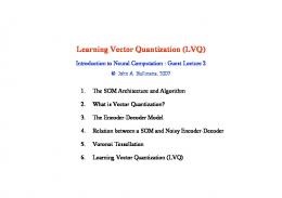
Chapter 2 Preliminaries Communication systems can vary drastically in terms of their features, their mode of work and their physical specifications. However, as depicted in Fig. 2.1, all of them have the same systemic configurations and elements. The basic part of every communication system is the information source. The source is then encoded and sent over a channel with certain statistical characteristics. At the receiver side, the received signal is estimated by a decoder and the sink of information uses the decoded information. The encoding and decoding blocks usually are divided into two independent parts: the source and the channel encoder/decoder. The source encoder and decoder together form the source coding section of the system, while the channel encoder and decoder pair form the channel coding section. In joint source-channel coding (JSCC) systems, the source and channel encoders
12
CHAPTER 2. PRELIMINARIES
13
Encoding Block
Source
Source Coding
User
Channel Encoder
Source Encoder
Channel Coding
Channel
Channel Decoder
Source Decoder
Decoding Block
Figure 2.1: Communication system model. may be coordinated or combined into a single operation. The purpose of the source encoder is to remove the statistically redundant information from the source while the channel encoder adds controlled redundancy to the source coded data in order to make the decoding process easier and more efficient.
2.1
Source Coding and Vector Quantization
The information source can be modeled by a random process which is an infinite sequence of random variables. Depending on the probabilistic nature of this process the information content of the source may be different. The goal of source coding
CHAPTER 2. PRELIMINARIES
14
is to remove the redundancy in the source so that the bit rate needed for it to be transmitted or stored is reduced. Two main features of every source are its embedded amount of information (entropy) and existence of correlation between its successive outputs (memory). Accordingly, the redundancy in every source involves two kinds of statistical redundancy: redundancy due to the source’s non-uniformity and redundancy due to memory. The former is manifested through the notion of marginal entropy and the latter by the concept of the source’s probabilistic dependence and is manifested by the concept of entropy rate. In general, source coding can be divided into two categories: lossless and lossy source coding. In lossless source coding, the coded information represents the source completely. This means that the source code can be decoded such that the original data and the recovered data are identical. When dealing with continuous-amplitude sources, however, lossless coding is not possible, and one has to use lossy source coding techniques such as quantization.
2.1.1
Lossless Source Coding
If the source alphabet is finite, it can be represented without loss, using sequences from a finite code alphabet. In lossless source coding, a discrete source is replaced by a discrete source code containing as little redundancy as possible. In this regard, the bit rate (or simply rate) of a source code is a fundamental figure of merit. The
CHAPTER 2. PRELIMINARIES
15
code rate is defined as the number of bits it assigns to each source sample on average. Therefore, if the length of the codewords are different as in variable length lossless source coding, the rate is defined as
r=
¯ L k
bits per symbol (bps),
(2.1)
¯ is the average (expected) codeword length and k is the length of the source’s where L block that is encoded. However, if we want to losslessly represent a source with alphabet X , using a fixed-length source binary-code, then the code rate is simply defined as
r=
L , k
(2.2)
where L is the length of source codewords. In such case, to encode k samples of the source (block length k), we need |X |k codewords, implying
r=
L ≥ log2 |X |, k
where |X | denotes the number of elements in X . Thus, the naive fixed-length bit representation of a source X needs log2 |X | bps. However, this is not the best coding scheme and the source may have some redundancy that can be removed by using variable length codes. To formulate this redundancy, the source entropy is defined as follows.
CHAPTER 2. PRELIMINARIES
16
Entropy: For a discrete random variable X (representing a discrete memoryless or independent and identically distributed (i.i.d) source) with probability mass function p(x), the entropy H(X) is defined by H(X) = −
�
p(x) log2 p(x) = E [− log2 p(X)] ,
(2.3)
x∈X
where E denotes statistical expectation. The larger is the entropy of a source, the more information it contains, or, equivalently, it is more unpredictable. It can be shown that the entropy represents the number of bits required to represent samples of the source output with no redundancy. The statistical redundancy due to the source non-uniformity is thus defined as the difference between log2 |X | and H(X) ρs = log2 |X | − H(X).
(2.4)
For a discrete memoryless source (DMS) the entropies of all of the source samples Xk , are the same and are equal to the entropy of the first (or any) output H(X1 ). However, the entropy of single source samples is not the rate limit for lossless compression for sources with memory. Such sources can be further compressed, exploiting the memory of source outcomes. For a source {Xn }∞ n=1 with memory, the “entropy rate” represents the average amount of information the entire source contains and is defined as H(X ) = lim
n→∞
1 H(X1n ), n
(2.5)
CHAPTER 2. PRELIMINARIES
17
where X1n denotes (X1 , X2 , · · · , Xn ). It can be shown that the entropy rate of a DMS is equal to the entropy of any one of its outputs. In fact, for a DMS 1 H(X1n ) = H(X1) = H(X), n
(2.6)
while for a stationary source with memory (e.g., a stationary Markov source), it can be shown that
H(X ) ≤
1 H(X1n ) ≤ H(X). n
Therefore, due to its memory, a Markov source contains less information than a DMS with identical marginal distribution. In general, the memory-based redundancy of a stationary source {Xn }∞ n=1 is defined as ρm = H(X) − H(X ),
(2.7)
where H(X) is the marginal entropy of any output of the source. The overall redundancy is therefore the sum of both ρs and ρm ρt = ρs + ρm = log2 |X | − H(X ).
(2.8)
Shannon showed for the first time [48] that it is possible to construct source codes that remove the redundancy of a source entirely, while keeping the code lossless, given that the rate of the code is greater than the entropy (or entropy rate in case of
CHAPTER 2. PRELIMINARIES
18
sources with memory). Specifically, he proved this fact in the course of his source coding theorems for different sources (memoryless or with memory) and coding schemes (fixed-length or variable length). Roughly speaking, the source coding theorems imply that the minimum possible rate for the codes to be lossless are the entropy for memoryless sources and the entropy rate for sources with memory. Hence the entropy (or entropy rate) is a fundamental parameter related to every discrete source.
2.1.2
Lossy Source Coding: Vector Quantization
In many cases, there is no possibility to reconstruct the source with zero distortion. If, for example, a continuous-valued source is to be sent over a digital channel, it is inevitable to lose some information. In such cases, source coding is referred to as lossy source coding. The most important case of analog-to-digital conversion is quantization. A quantizer receives an analog input (e.g., temperature) and assigns the closest value in its output set (e.g., the closest digital temperature value in a digital thermometer) to the analog information. A scalar quantizer (SQ) is specified by its encoding (E ) and decoding (D) mappings. The encoding function maps the real line to a set of indices I = {0, 1, · · · , N − 1} and the decoding function maps every index to a point on the real line, which is
CHAPTER 2. PRELIMINARIES
19
usually called an output level. In summary E : R → I = {0, 1, · · · , N − 1}, D : I → C = {c0 , c1 , · · · , cN −1 }. The scalar quantizer is the composition of encoding and decoding functions: Q =D ◦E :R→C and the rate of the quantizer is
r = log2 N bps.
(2.9)
ˆ ∈ C in a quantiTherefore, the source output X ∈ R is replaced by Q(X) = X −1 zation source coding system. The encoder E induces a partition P = {Si }N i=0 of R
and assigns indices to X based on the region in which X is located. An important example of scalar quantizers is the uniform quantizer. The uniform quantizer divides the domain of the input signal into equal-sized cells and the output levels are the centers of the cells. Uniform quantizers have very low complexity which makes them applicable in many situations other than data compression, including companding and soft-decision demodulation. To have a measure of the performance of the quantization system, we need to define ˆ estimates X. First we define a quantitative parameter measuring how accurately X ˆ The a “distance” between x and xˆ as outcomes of the random variables X and X. distortion is the probabilistic average of the distance between two random variables.
CHAPTER 2. PRELIMINARIES
20
The measure of distance between x and xˆ is denoted by d(x, x ˆ) and can have different forms such as absolute error (|x − xˆ|) and squared error (|x − xˆ|2 ). Because of its simplicity and wide use, in this thesis we use the squared error distortion measure d(x, x ˆ) = |x − xˆ|2 .
(2.10)
Based on the above the distortion of the scalar quantizer is defined as � � � � 2 ˆ ˆ D = E d(X, X) = E |X − X| .
(2.11)
Vector quantization (VQ) is a generalization of scalar quantization to the coding of a source output vector into an index from a finite set. Thus the vector X ∈ Rk is ˆ is quantized into a set of indices I = {0, 1, · · · , N − 1} and the recovered vector X chosen from a set of code vectors C = {c0 , c1 , · · · , cN −1 } ⊂ Rk . The set C is called the codebook and has N elements, each a vector in Rk . The vector quantizer is therefore defined as a function Q : Rk → C, which is itself a combination of an encoder (E ) and a decoder (D). The number of bits per source symbol determines the rate of the VQ and is given by r=
log2 N k
bps.
(2.12)
The notion of distortion in vector quantization is also the same as that in scalar quantization � � �� � � ˆ ˆ 2 , D = E d X, X = E X − X
(2.13)
CHAPTER 2. PRELIMINARIES
21
where · denotes the standard Euclidean norm in Rk . As in scalar quantization, the encoder function divides the input space Rk into N encoding regions given by P = {S0 , S1 , · · · , SN −1 } which are multi-dimensional cells. This provides extra degrees of freedom in choosing different shapes for the quantizer cells; a feature that makes the VQs more demanding in terms of variety of the simple cell shapes (like cubes, regular polyhedra, etc.), all of which are the counterparts of the uniform SQ. The advantages of VQ over SQ [22, 39] are not limited to this case but they also include factors such as the ability to exploit the dependence of vector components and to make fractional bit rates per symbol possible. It is also shown that when the quantization dimension goes to infinity, the ultimate limits of rate-distortion theory can be achieved [22]. The rate-distortion theorem is the counterpart of the lossless source coding theorems for lossy source coding. It formulates the relation between the available source coding rate and the minimum achievable distortion. We state the theorem since it is an important part of source coding theory. For this purpose, we first define the concept of mutual information between two RVs. Mutual Information: The mutual information between two random variables ˆ with common alphabet X is defined as X and its reproduction X, ˆ = H(X) − H(X|X) ˆ I(X; X) ˆ − H(X|X) ˆ = H(X) = −
� x∈X
p(x) log2
p(x, xˆ) . p(x)p (ˆ x)
(2.14)
CHAPTER 2. PRELIMINARIES
22
where p(·) is the probability distribution over a corresponding set. The definition can be generalized to vector and continuous valued RVs. The mutual information represents the amount of information that one random variable gives about the other one. Now, we can state the rate-distortion theorem. Theorem. [11] Rate-Distortion Theorem For an i.i.d source X with distribution p(x) and bounded distortion measure d(x, xˆ) we have the following equality r(D) =
ˆ inf I(X; X) ˆ p(ˆ x|x):E[d(X,X )]≤D
(2.15)
where r(D) is called the rate-distortion function and represents the infimum of rates for which there is a lossy source code (e.g., vector quantizer) with asymptotic distortion less than or equal to D. ˆ Therefore, according to the rate-distortion theorem, one should minimize I(X; X) over all conditional distributions p(ˆ x|x) such that �� x
d(x, x ˆ)p(ˆ x|x)p(x) ≤ D
x ˆ
in order to compute the rate-distortion function r(D).
2.1.3
Optimality Criteria for Vector Quantizers
An optimal VQ is one that, for a given number of output levels N, minimizes the ˆ As a result, distortion between the source vector X and the reproduction vector X.
CHAPTER 2. PRELIMINARIES
23
the goal of the VQ designer is to find the encoding and decoding pair (E , D) with the least possible distortion, subject to a rate constraint. From Equation (2.13), we can write the distortion of the VQ in a more detailed form. Assuming the probability density function (pdf) p(x) for the source X ∈ Rk , we have
DV Q
� 1 � 2 ˆ = E X − X k N −1 � 1 � � E X − cj 2 |X ∈ Sj P (X ∈ Sj ) = k j=0 N −1 1 � p(x) x − cj 2 dx. = k j=0 Sj
(2.16)
It is generally an unsolved problem to find the codebook C and encoder partition −1 P = {Si }N i=0 that minimize DV Q . However, two important necessary conditions for
optimality are known [22]. The first condition is called the nearest neighbor condition (NNC) which applies to the encoder E . The second necessary condition provides a criterion for the decoder D and is called the centroid condition (CC). Nearest Neighbor Condition [22] Assume that we have a vector quantizer with codebook C = {c0 , c1 , · · · , cN −1 }. ˆ ∈ C, we have For the source sample x ∈ Rk with reproduction x ˆ ) = x − x ˆ 2 d(x, x ≥ min x − cj 2 . cj ∈C
CHAPTER 2. PRELIMINARIES
24
−1 In such a case, if the VQ is optimal, the encoding regions P = {Si }N i=0 are given
by � � Si = x ∈ Rk : x − ci 2 ≤ x − cj 2 , ∀j �= i ∈ I .
(2.17)
Thus the encoding function for a specific codebook C should be E (x) = arg min x − ci 2 .
(2.18)
i∈I
Centroid Condition [22] The second necessary condition for the optimality of a VQ is called the centroid condition. It assigns the optimal codebook to a given encoding partition P. In other −1 words, for given encoding regions {Si }N i=0 , the VQ can only be optimal if the output
codevectors are the centroids of the encoding regions
ci = E{X|X ∈ Si } = x∈Si
xp(x)dx
x∈Si
p(x)dx
.
(2.19)
Indeed it can be shown that the optimal decoding function for the known quan−1 tization regions {Si }N i=0 is given by
� � D(j) = cj = arg min E X − y 2 |X ∈ Sj ,
(2.20)
y∈Rk
where cj is called the centroid of the quantization cell Sj . Equations (2.19) and (2.20) can be verified by solving ∂DV Q = 0, ∂cj
CHAPTER 2. PRELIMINARIES
25
for cj , where DV Q is given by Equation (2.16). In practice, we deal with the training vector outputs of the sources instead of the analytic probability density functions. Therefore in practical VQ design algorithms, we compute sums instead of integrals and the cells are subsets of the training vectors. In light of the works of Lloyd [35] and Max [36], a quantizer that satisfies both NNC and CC conditions is called a Lloyd-Max quantizer. The necessary conditions are also sometimes referred to as Lloyd-Max conditions. Both necessary conditions can be applied to scalar quantizers as well as vector quantizers. Thus, NNC and CC are sometimes called generalized Lloyd-Max (or simply generalized Lloyd) conditions when referring to vector quantization.
2.1.4
Vector Quantization Design
On the basis of the necessary conditions of optimality, several design algorithms have been proposed, all of which incorporate some kind of iterative process which uses the NNC and CC alternatingly. The first paper to address the problem of finding the partition set P ∗ and codebook C ∗ such that the distortion in (2.16) is minimized is the one by Linde, Buzo and Gray [34]. Their algorithm is called the LBG algorithm (also known as the generalized Lloyd algorithm (GLA)). According to the LBG algorithm, −1 given the initial codebook C, the partition set P = {Si }N i=0 is calculated using (2.17)
and for the computed partition set P, the new codebook is calculated using (2.19).
CHAPTER 2. PRELIMINARIES
26
It can be shown [22], that in each iteration, the resulting distortion decreases or stays the same. The process continues until the relative improvement of the distortion is less than a certain threshold. This gives us a locally optimal solution to the problem (theoretically this means that there may exist other codebooks that give lower values of distortion [22, 34]). This method can be useful for both scalar and vector quantization. An important aspect of the LBG-VQ algorithm is the choice of the initial codebook. Several methods for choosing the first N code vectors have been proposed in the literature. One option is, for example, to choose the first N vectors of the training sequence. In this thesis and in our simulations, however, we will always use the so called splitting method [22, 34] to set the initial codebook in the design of the VQ. In the splitting algorithm, the first code vector is the centroid of the training sequence. This point is then “split” into two points (by perturbing with a vector of small Euclidean norm), for which a two-level LBG quantizer is designed. The splitting process is applied then to the reconstruction vectors of the two-level VQ creating four initial code vectors for a four-level VQ. This procedure continues until we end up with N = 2n (n ∈ N) initial code vectors for the desired N-level VQ. The LBG-VQ algorithm is therefore summarized as follows.
CHAPTER 2. PRELIMINARIES
27
LBG-VQ Design Algorithm [22, 34]
1. Let N = 2n be the number of reconstruction vectors, k the dimension of the VQ, and M the number of training vectors {xm }M m=1 . Also choose a fixed � > 0 as the target stopping threshold and δ as the perturbation constant for the splitting algorithm. N � is the counter for the number of code vectors and j is iteration counter. 2. Start: Let N � = 1 and 1 � = xm M m=1 M
c∗0
as the only code vector for the one-level quantizer. The globally optimal onelevel codebook of a training sequence is the centroid of the entire sequence. Calculate D (1) = D ∗ =
M 1 � xm − c∗0 2 kM m=1
as the initial and optimal average distortion of the one-level quantizer. Thus the first initial codebook found for the one-level quantizer (which ia also optimal) (1)
is C1 = C1 ∗ = {c∗0 }. While N � < N, repeat steps 3, 4 and 5. (1)
3. Splitting: To find the initial codebook of N � -level quantizer CN � from the
CHAPTER 2. PRELIMINARIES
28
∗ optimal codebook of N � /2-level quantizer CN � /2 , set (1)
ci = c∗i + δ, (1)
ci+N � = c∗i − δ, for i = 0, 1, · · · , N � − 1, where δ is a constant perturbation vector given by δ = δ1, where 1 is an all-one vector of dimension k (see [22] for data-dependent choices of δ). Note that the superscripts indicate the iteration number, the ∗ superscript denotes the optimal and eventual parameters of each iteration and the subscripts for codebooks (if shown) indicate the number of output levels (N � ). Set N � = 2N � . 4. Iteration (a) Set the initial distortion D (1) = D ∗ and the iteration counter j = 1. (j)
(j)
(j)
(b) Given jth codebook C (j) = {c0 , c1 , · · · , cN � −1 }, assign each training vector xm to its corresponding encoding region to determine the jth partition � (j) N −1
cell P (j) = {Si }i=0
according to the rule
(j) 2
E (j) (xm ) = arg min xm − cl , l ∈ IN �
m = 1, 2, · · · , M,
where IN � = {0, 1, · · · , N � − 1}. In other words, define the quantizer function Q as
CHAPTER 2. PRELIMINARIES
29
Q (j) (xm ) = arg min xm − c 2 ,
m = 1, 2, · · · , M.
c ∈ C (j)
(c) Compute the new codebook C (j+1)
(j+1)
ci
� (j) xm S (j) = i , = E X|X ∈ Si (j) 1 S
i = 0, 1, · · · N � − 1.
i
(d) Set j = j + 1. (e) Compute the updated distortion
1 � 2 = xm − Q (j) (xm ) . kM m=1 M
D
(j)
� � (f) If D (j−1) − D (j) /D(j−1) > �, go to step (4b). (g) Set the final codebook for this iteration as
(j)
c∗i = ci ,
i = 1, 2, · · · , N �
and set D ∗ = D (j) . 5. Go to step 3 and repeat the splitting and iteration procedures until N � ≥ N. For design purposes, the values of stopping threshold and perturbation constant has been set to � = δ = 0.001 as in [2] and [41].
CHAPTER 2. PRELIMINARIES
2.2 2.2.1
30
Channel Models Discrete Memoryless Channel (DMC)
A discrete channel is a communication channel defined by finite input alphabet X , finite output alphabet Y and a set of transition probabilities PY |X (y|x) � P r{Y = y|X = x}, ∀ x ∈ X , ∀ y ∈ Y,
(2.21)
which determines the probability of receiving y at the output of the channel given x is transmitted. The transition probabilities are sometimes written in a |X | × |Y| matrix form and the resulting matrix is called the transition matrix. More generally, if a sequence of input symbols X = {X1n } is sent in n successive time indices over the channel and a sequence Y = {Y1n } is received at the output, the channel is described by n-dimensional distributions PY|X (y|x) � P r{Y = y|X = x}, ∀ x ∈ X n , ∀ y ∈ Y n .
(2.22)
A discrete memoryless channel (DMC) is a discrete channel for which the output of the channel at each time index depends only on the input of the channel at the same time index. Therefore, its n-dimensional distribution can be written as the product of the transition probabilities at different time instants: n � PY|X (y|x) = PY |X (yj |xj ), j=1
(2.23)
CHAPTER 2. PRELIMINARIES
31
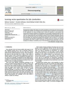
where xj and yj are the outcomes of random variables Xj and Yj . DMCs are useful and simple models for real-world channels and are widely used in the literature. One important, yet simple example of the DMC is the binary symmetric channel (BSC). The BSC (Fig. 2.2) is a DMC with X = Y = {0, 1} and PY |X (0|1) = PY |X (1|0) = ε. X
Y
0
1−ε
0
1−ε
1
ε
ε
1
Figure 2.2: The binary symmetric channel with crossover probability ε. The most significant parameter related to every channel is its associated channel capacity. The capacity of a DMC is defined as C = max I(X; Y ),
(2.24)
p(x)
where the maximum is taken over all channel input distributions p(·). Shannon has shown [48, 11] that the capacity is the maximum of all data rates r that can be reliably sent over the channel. Indeed, reliable transmission of information
CHAPTER 2. PRELIMINARIES
32
at a fixed data rate r is possible if and only if r < C.
2.2.2
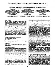
Additive White Gaussian Noise (AWGN) Channel
The AWGN channel (or simply Gaussian channel) is a continuous-alphabet discretetime channel with input Xi ∈ X = R and output Yi ∈ Y = R at time i, where X , Y denote the input and output alphabets respectively. As depicted in Fig. 2.3, the output Yi, at any time instant, is the sum of the input Xi and a real random variable νi known as the channel noise. The noise νi is drawn i.i.d (white) from a Gaussian distribution with zero mean and power E[νi 2 ] = N0 . Thus Yi = Xi + νi ,
νi ∼ N (0, N0).
(2.25)
Yi
Xi
νi Figure 2.3: The AWGN channel model.
The noise νi is assumed to be independent of Xi . The AWGN channel is one of the most important communication channel models. It models many real-world communication channels, such as satellite and wireless telephone channels with an acceptable accuracy.
CHAPTER 2. PRELIMINARIES
2.2.3
33
Rayleigh Fading Channel
The Rayleigh fading channel is depicted in Fig. 2.4. It is also a continuous-alphabet and discrete-time channel with input Xi ∈ X = R and output Yi ∈ Y = R. The difference between the Rayleigh fading channel and the AWGN channel is that the input Xi is now multiplied by a so-called fading coefficient hi which attenuates it before the Gaussian noise νi is added. The relation between the input and the output of the Rayleigh fading channel is given by
Yi = hi Xi + νi ,
νi ∼ N (0, N0),
(2.26)
where the fading coefficient hi is an i.i.d Rayleigh RV with pdf ⎧ ⎪ −h2 ⎪ ⎨ h2 e 2σ2 , for h ≥ 0, σ pH (h) = ⎪ ⎪ ⎩ 0, otherwise,
(2.27)
� � where E hi 2 = 2σ 2 and its mean is given by � E[hi ] = σ
π . 2
(2.28)
Yi
Xi
hi
νi
Figure 2.4: The Rayleigh fading channel model.
CHAPTER 2. PRELIMINARIES
34
� � Throughout this thesis, the second moment E hi 2 is usually assumed to be 1. Note that this assumption can be made without any loss of generality.
2.3
Channel Optimized Vector Quantization
So far all source coding methods described in the previous sections disregarded the channel. In pure source coding systems, the output of the encoder E is directly fed to the input of the decoder D. Vector quantization, the most important source coding scheme we reviewed, for instance, does not assume any statistical index perturbation between the encoder and decoder. However, noise makes an inevitable and notable effect in real-world communication systems. Improving the VQ under the conditions of probabilistic index perturbation between the input and output of the channel is the subject of joint source-channel coding. The resulting VQ is called a channel optimized vector quantizer (COVQ). Thus the basic idea of the COVQ is to design a VQ by incorporating the channel conditions into the design algorithm, trading off the quantization and channel noise in order to minimize the end-to-end distortion. One proven advantage of the COVQ is that there is no need to add error-protection intended redundancy to the system and its performance is acceptable even without that sort of extra redundancy. However, there are some proposed schemes that use mixed strategies (e.g., see [23]). Necessary conditions for COVQ optimality were first derived by Kumazawa et al. [30]. Farvardin
CHAPTER 2. PRELIMINARIES
35
and Vaishampayan studied the complexity and performance of COVQ in [16]. They considered COVQ problems with the so-called degenerate partition in which (unlike VQ), it is possible to have encoding regions of zero probability (Pi = 0) referred to as empty cells. They showed that the number of non-empty quantization cells, i.e., cells with at least one training vector, determines the complexity of the system. They also showed the interesting fact that for more noisy channels, there are more empty cells resulting in non-uniform index distribution at the channel input. In this thesis we use this feature to improve the performance of COVQ systems.
2.3.1
COVQ System Model and Design Algorithm
Fig. 2.5 depicts the COVQ system. It can be seen that the difference between the COVQ and the VQ systems is the existence of the DMC with the transition distribution PY |X . The goal of the system is to transmit the random vector X ∈ Rk over the ˆ of X such that the distortion E X − X ˆ 2 is minimized. DMC and form an estimate X The COVQ encodes X at a rate of r =
log2 N k
bps. Therefore, the COVQ encoder is
a mapping E : Rk → I � {0, 1, · · · , N − 1}, and E (X) = I is sent over the DMC. The encoding is done using the decision regions −1 kr P = {Si }N i=0 (N = 2 ) via the encoding rule:
X ∈ Si ⇔ I = E (X) = i.
CHAPTER 2. PRELIMINARIES
36
The a priori probability of the indices to be chosen are denoted by Pi , where Pi = Pr [X ∈ Si ].
I ∈ I = {0, 1, · · · , N − 1} X ∈ Rk
X ∈ SI
E (.)
DMC (PY |X (J|I)) ˆ ∈ Rk X
ˆ = cJ X
D(.)
J ∈ J = {0, 1, · · · , N − 1} Figure 2.5: General block diagram of a COVQ system. The input alphabet of the DMC is I = {0, 1, · · · , N − 1}. Each input index is transmitted over the channel and is received through a transition matrix PY |X . The output alphabet set is J = {0, 1, · · · , N − 1}. Depending on the decoding scheme, J can be the same as I or different. If the system uses hard-decision demodulation J = I. There are some cases, however, where the input and output sets are different. In soft-decision demodulation (SDD) COVQ systems the resolution of the decoder mapping is higher than the encoder’s because of the intention of the system to use the soft information in the received signals. This results in a larger number of DMC outputs than inputs. The decoder D assigns to the received index J, a code vector cj from a codebook
CHAPTER 2. PRELIMINARIES
37
C = {c0 , c1 , · · · , cN −1 }. As in the case of VQs, we are looking for the optimal P and C to minimize the distortion. The end-to-end distortion of the COVQ per sample can be written as
DCOV Q
� 1 � = p(x) PY |X (j|i)d(x, cj )dx k i Si j � 1 � = p(x) PY |X (j|i) x − cj 2 dx k i Si j � � 1 = PY |X (j|i) p(x) x − cj 2 dx, k i j Si
(2.29) (2.30)
where p(x) is the k-dimensional density of the source and PY |X (j|i) is the probability of receiving j when i is sent. For a given source, channel, quantization dimension k, and fixed rate r, we wish to find the optimal functions E ∗ and D ∗ , or equivalently the optimal partition P ∗ and codebook C ∗ . Comparing (2.29) with the distortion formula of the VQ in (2.16), one realizes that the problem of minimizing the COVQ distortion is the same as that of the VQ with a modified distortion measure. The global solution to this problem is also unknown as for the VQ problem. However, there are generalized versions of the NNC and CC conditions for the COVQ which make us able to find locally optimal solutions in the course of an iterative procedure, starting from a suitably chosen initial codebook. Generalized NNC [16] Let the codebook C be fixed. We want to determine the optimal encoding regions
CHAPTER 2. PRELIMINARIES
38
ˆ be the reproduction and x ∈ Si . Then we so as to minimize the distortion. Let X have N −1 � � � ˆ E d(x, X) = PY |X (j|i) x − cj 2 j=0
≥ min i
N −1 �
PY |X (j|i) x − cj 2 .
j=0
Thus, based on the above, it can be shown [30] that for a given codebook C, the optimal partition set is given by � � � � � PY |X (j|i) x − cj 2 ≤ PY |X j|ˆi x − cj 2 , Si∗ = x : j
� ∀ˆi ∈ I
(2.31)
j
for every i ∈ I = {0, 1, · · · , N − 1}. Therefore, the encoding function E can be written as E (x) = arg min i∈I
N −1 �
PY |X (j|i) x − cj 2 .
(2.32)
j=0
Note that the partition is degenerate [22], meaning that it is possible for the regions to be empty. Equivalently, there may exist an index i for which ∀x, ∃ˆi :
� j
2
PY |X (j|i) x − cj ≥
�
� PY |X
� ˆ j|i x − cj 2 ,
j
implying that Si∗ = ∅. In that case the index i is not transmitted by the encoder. Generalized CC [16] In a similar way, the generalized CC condition gives the code vectors for the given partition set P = {S0 , S1 , · · · , SN −1 } by
P (j|i) xp(x) dx Y |X i
Si c∗j = , j = 0, 1, · · · , N − 1. i PY |X (j|i) Si p(x) dx
(2.33)
CHAPTER 2. PRELIMINARIES
39
Like in VQs, as equation (2.20) suggests, the values of the decoding function D as −1 the optimal codevectors {cj }N j=0 given by (2.33) are also referred to as the centroids
since � � D(j) = c∗j = arg min E X − y 2 | J = j ,
(2.34)
y∈Rk
for j = 0, 1, · · · , N −1, where J is the random output index of the channel. Equations (2.33) and (2.34) can be proven by solving ∂DCOV Q = 0, ∂cj for cj , where DCOV Q is given by (2.29). In practice, instead of the analytic probability density function p(x), only samples from the source are available and we use the training sequences replacing the integrals with summations and the density function with empirical weights. Thus, for the training vectors {x1 , x2 , · · · , xM }, Equations (2.29) and (2.33) are modified as DCOV Q
M N −1 1 �� = PY |X (j|E (xi ))d(xi , cj ) kM i=1 j=0 M N −1 1 �� PY |X (j|E (xi )) xi − cj 2 = kM i=1 j=0
and
N −1
PY |X (j|i)
c∗j = i=0 N −1 i=0
(2.35)
Si x
PY |X (j|i) |Si |
,
where |Si | denotes the number of training vectors in the quantization cell Si .
(2.36)
CHAPTER 2. PRELIMINARIES
40
The COVQ design procedure is an extension of the LBG algorithm for VQ design, based on the generalized CC and NNC. The algorithm starts with an initial codebook C (0) and finds the best partition set P (1) for that codebook, using (2.31). Given the newly calculated partition set P (1) , the algorithm uses (2.36) to find the best codebook C (1) which reduces the distortion. The algorithm continues with similar steps and the distortion reduces in each cycle. The algorithm stops when the relative change in distortion becomes less than a given threshold � > 0. The essential part of the algorithm, similar to VQ design, is the way it chooses the initial codebook. The splitting algorithm alone is not enough for the selection of a good COVQ initial codebook. We explain the method we use in this thesis in the following subsection.
2.3.2
Initial Codebook Selection
Intuitively compared with VQ, the new source of distortion in COVQ is the channel noise. Thus one can conjecture that the overall distortion of the COVQ is the sum of the quantization and channel distortions. Indeed it can be shown [15] that if the −1 N −1 codevectors {ci }N i=0 are the centroids of the quantization cells {Si }i=0 (as in the
noiseless case given by Equation (2.19)), specifically if the quantizer is a Lloyd-Max quantizer, the distortion DCOV Q can be written as the summation of two terms. The first term represents the error introduced by the vector quantization for the ideal DMC (with the transition matrix IN ) and the second term is due to the noise of the
CHAPTER 2. PRELIMINARIES
41
channel. Thus, if the quantizer is a Lloyd-Max quantizer, we can write the overall distortion DCOV Q as DCOV Q = DV Q + DC ,
(2.37)
where DV Q is the quantization distortion given by DV Q
N −1 1� = p(x) x − ci 2 dx k i=0 Si
(2.38)
and DC is the channel introduced distortion and can be described as DC
N −1 N −1 1�� = PY |X (j|i)Pi d(ci , cj ) k i=0 j=0
=
N −1 N −1 1�� PY |X (j|i)Pi ci − cj 2 . k i=0 j=0
(2.39)
The above property is the result of the squared-error distortion measure and gives us a good insight to select the initial codebook. According to (2.37), in order to minimize the distortion of the quantizer (DV Q ), we should first design a Lloyd-Max VQ using the LBG algorithm to minimize the first term. The VQ is designed using the splitting algorithm as the initial codebook selection. The second term can also be minimized over the order of the set {0, 1, · · · , N − 1}. In fact as Equation (2.39) suggests, DC is a function of the assignment of the indices to the code vectors and quantization regions. If, for example, one changes the order of the codevectors C = {c0 , c1 , · · · , cN −1 } without changing the codevectors themselves and renames the new set as C � = {c�0 , c�1 , · · · , c�N −1 }, the corresponding channel distortions will be different.
CHAPTER 2. PRELIMINARIES
42
Therefore, we define the index assignment function b:I→I and minimize DC over b(·). The resulting codebook is the initial codebook which is then used by the COVQ design algorithm. To find the best index assignment function b we use a method called simulated annealing (SA) [16]. This method is a stochastic relaxation algorithm and has been applied to many different problems. The SA algorithm tries to find the optimal state of the system in terms of an objective function (energy) by changing temperature. An initial state is first defined and the next state is generated in a probabilistic way according to the temperature. The SA algorithm converges to the global minimum of the system in probability. In the context of our index assignment problem, every index assignment (b(c0 ), b(c1 ), · · · , b(cN −1 )) is a state of the system and the resulting distortion DC is the energy or objective function of the hypothetical system. We also use a so-called cooling schedule given by Tk = αTk−1,
0 ≤ α ≤ 1.
(2.40)
Based on the above assumptions, the SA algorithm steps can be summarized as follows: 1. Randomly choose an initial state b and raise the temperature to an initial high amount T0 .
CHAPTER 2. PRELIMINARIES
43
T0
10.0
Tf
0.00025
α
0.97
Ncut
200
Table 2.1: Simulated annealing parameters. 2. Choose the next state b� randomly and calculate the change in energy ΔDC = DC (b� ) − DC (b). If ΔDC ≤ 0, replace b with b� and go to step 3. Otherwise, replace b with b� with probability e−ΔDC /T and go to step (3). 3. If there is no energy drop after a specific number of perturbations Ncut , go to step (4). Otherwise go to step (2). 4. Decrease the temperature according to Equation (2.40). If the temperature is less than a prescribed freezing temperature Tf or the systems appears to be stable (not much energy change) stop with b as the final state. Otherwise go to step (2). The SA algorithm parameters we have used in this thesis are the same as those used in [14, 16] and are listed in Table 2.1.
Chapter 3 Iterative MAP Decoded COVQ In this chapter, the iterative MAP decoded algorithm to design COVQ for harddecision demodulated AWGN and Rayleigh fading channels is proposed in detail. Soft-decision demodulation (SDD) COVQ is introduced and the advantages of the IMD algorithm over conventional COVQ discussed in Section 2.3 and SDD COVQ are presented. It is also shown that the IMD COVQ outperforms conventional COVQ and SDD COVQ in terms of encoding complexity and storage requirements. An empirical convergence analysis for the proposed algorithm is provided at the end.
3.1
IMD COVQ System
The general block diagram of the IMD COVQ system is depicted in Fig. 3.1. The channel can be either AWGN or Rayleigh fading. As in the case of conventional 44
CHAPTER 3. ITERATIVE MAP DECODED COVQ
45
COVQ, the purpose of the system is to transmit the random vector Xn ∈ Rk of dimension k over the noisy channel and reproduce it by Xˆn at the receiver with the aim of minimizing the overall expected mean square error distortion. Here, n represents the time index of the vector which consists of k single source outputs so that Xn ∈ Rk . The source {Xn } is assumed to be a stationary ergodic process, with zero mean and unit variance. The COVQ encoder encodes {Xn } at a rate of r bits per sample (bps). Therefore, the COVQ encoder is a mapping E : Rk → In � {0, 1, · · · , Ne − 1} = {0, 1}kr where {0, 1}kr represents the binary representation of the indices. Thus, the binary representation of E (Xn ) = In is modulated and sent over the channel in kr consecutive channel uses. In this thesis, we use binary phase-shift keying (BPSK) modulation, although other memoryless modulation techniques can also be considered. The encoding is Ne −1 done using the decision regions {Si }i=0 (Ne = 2kr ). The input index probability
distribution, as in conventional COVQ, is denoted by Pi for i = 0, 1, · · · , Ne − 1. BPSK modulated bits with unit energy are denoted by Wn1 , Wn2 , · · · , Wnkr and form the vector Wn ∈ {−1, +1}kr . Each symbol is transmitted over the physical channel, assuming that the channel is memoryless, i.e., the potentially corrupted received symbol is only a function of transmitted symbol at the same time unit. As a result, the received vector Rn consists of kr consecutive received values: Rn1 , Rn2 , · · · , Rnkr
CHAPTER 3. ITERATIVE MAP DECODED COVQ
46
Equivalent Discrete Memoryless Channel (DMC)
Discrete−time
Xn ∈ Rk
COVQ Encoder
In ∈ {0, 1}kr
E(.)
Source
BPSK Modulator
Wn ∈ {−1, +1}kr
Channel Decoder Set User
COVQ Decoder
Xˆn ∈ Rk
D2 (.)
Jn ∈ {0, 1}kr
Detector (MAP decoder) D1 (.)
Rn ∈ Rkr
Figure 3.1: Block diagram of the iterative MAP decoded COVQ system. that can each be written as Rnt = Wnt + νt ,
t = 1, 2, · · · , kr,
(3.1)
for the AWGN channel and Rnt = ht Wnt + νt ,
t = 1, 2, · · · , kr,
(3.2)
for the Rayleigh fading channel, where {νt } is the sequence of independent and identically distributed (i.i.d) Gaussian random variables: νt ∼ N (0, N20 ), and {ht } is the i.i.d amplitude fading process with the probability density function (pdf) ⎧ ⎪ ⎪ 2 ⎪ ⎨2h e−h , if h ≥ 0, pH (h) = ⎪ ⎪ ⎪ ⎩0, otherwise.
(3.3)
CHAPTER 3. ITERATIVE MAP DECODED COVQ
Note that E [h2t ] = 1, with σ 2 =
1 2
47
compared with the standard form of Equation
(2.27). We also assume that ht , νt and Wnt are independent of each other for all t and the fading amplitude values ht are perfectly known at the receiver (perfect channel side information (CSI) at the decoder side). The knowledge of CSI is necessary for symbol MAP decoding which is used in our system. In ML decoding used in conventional COVQ, however, it is an advantage of BPSK (and more generally all the PSK systems) that the decoder does not have to know the channel coefficient ht as opposed to other constellations, where it is usually assumed that the CSI is known perfectly at the receiver. The concatenation of the modulator, the actual channel and the detector form a DMC. We refer to this discrete channel as the “equivalent DMC”. The transition probabilities of the equivalent DMC can be determined in terms of the actual channel parameters. In particular, in ML-decoded channels, they are the symbol Pairwise Error Probabilities (PEP). The input alphabet of the DMC is In = {0, 1, · · · , Ne − 1}. Each input index is transmitted over the equivalent DMC and is received through a transition matrix PY |X . The output alphabet is Jn = {0, 1, · · · , Nd − 1}. Depending on the decoding scheme, Jn can be the same as In or different. Since our system uses hard-decision demodulation Jn = In and Nd = Ne . In soft-decision demodulation (SDD) schemes, however, the index resolution of the receiver side is larger than the transmitter side
CHAPTER 3. ITERATIVE MAP DECODED COVQ
48
(Nd > Ne ). Hard-decision decoding has less decoding complexity than systems employing soft decoding or soft-decision demodulation (e.g., [2], [7], [41], [50], and [54]). The decoder is the combination of two functions D1 and D2 . Thus the decoder can be written as D = D2 ◦ D1 , where: D1 : Rkr → Jn = In = {0, 1, · · · , Ne − 1}, D2 : Jn → Rk and ◦ denotes function composition.
3.2
Three Phase IMD Algorithm
The main contribution of this thesis is an algorithm, referred to as the IMD algoritm, that jointly optimizes D1 and the pair {D2 , E }. The IMD algorithm is motivated by the non-uniform input distribution that the COVQ design procedure creates. In case the channel is very noisy, we have even many empty encoding cells, meaning that no training vector has been assigned to them. This inspires us to use MAP decoding to improve the performance of the system. The IMD algorithm consists of three phases. The first phase is the ordinary COVQ design algorithm introduced in Section 2.3. Hence, the COVQ encoder and decoder are designed for the initial DMC. The COVQ encoder E : Rk → In is characterized in terms of a partition [16] P = {Si ⊂ Rk : i ∈ In }. The initial DMC, formed by the BPSK modulator, channel and
CHAPTER 3. ITERATIVE MAP DECODED COVQ
49
bit-wise ML-decoder, takes the input index In and produces the output Jn . The decoder mapping D2 : Jn → Rk is represented by the codebook C = {cj ∈ Rk : j ∈ Jn }. In practice, only samples from the source are available and we use the training data. Therefore, in the first phase, the COVQ encoder and decoder are iteratively optimized based on the Lloyd-Max necessary conditions of (2.31) and (2.36), ending up with a locally optimal solution. Thus, in the first phase D1 is fixed and E and D2 are alternatingly optimized in an iterative fashion. From (2.35), for the above system, the average distortion per sample is given by [16] Dn
1� = k i
p(x) Si
�
PJn |In (j|i) x − cj 2 dx
(3.4)
j
where p(x) is the k-dimensional source density. Note that in the first step of the iteration, we assume a uniform input index distribution which results in ML decoding for the first part of the decoder D1 . In this case the DMC is a binary symmetric channel (BSC) used kr times independently and the symbol transition probabilities are kr long products of the bit transition probabilities. Once Phase 1 is complete, the bit-wise ML decoder is replaced by the symbol-wise MAP decoder. The encoder index distribution Pi for i = 0, 1, · · · , Ne − 1 is then fed to the MAP decoder to start the second phase of the algorithm. Thus we use the computed input distribution to replace the ML detector by a symbol based MAP
CHAPTER 3. ITERATIVE MAP DECODED COVQ
50
decoder and redesign the COVQ.
3.2.1
MAP decoding
For the second phase of the algorithm, given D2 and E from the first phase, we find D1 such that the MAP metric is maximized. This replaces the channel transition distribution matrix with a new transition matrix. For the updated channel distribution, we redesign the COVQ as the main step of the second phase of the algorithm. In order to compute the new channel transition distribution, we need to compute the MAP metric of the channel for the COVQ designed in the previous step. Note that only the input distribution is required from the previously designed COVQ for the new transition matrix computation process. The MAP metric calculations for AWGN and Rayleigh fading channels are discussed in the following two subsections. MAP metric for AWGN channel According to (3.1) for the AWGN channel, given the received vector Rn , the first decoder D1 chooses the decoded index Jn (from the set of Jn ) which maximizes the the MAP metric through the following equations Jn = arg max P (In |Rn ) = arg max P (Rn |In )Pin In
In
= arg max P (ν = Rn − Wn (In ) |In ) Pin In � � �� kr 2 � − (Rnt − Wnt ) 1 √ = arg max exp × Pin In N πN 0 0 t=1
CHAPTER 3. ITERATIVE MAP DECODED COVQ � � � 1 2 = arg max exp − Rn − Wn × Pin In N0 � � 1 2 = arg min Rn − Wn − ln Pin , In N0
51
�
(3.5)
where Wn (In ) is the BPSK signal corresponding to In , Pin is the empirical weight of the index In obtained in the first phase and ν is the kr dimensional vector of Gaussian noise elements (ν1 , ν2 , · · · , νkr ). Based on the above MAP metric, given the index In is transmitted the probability of receiving index Jn , PY |X (Jn |In ), is ��
� 1 2 Wn (In ) + ν − Wn (Jn ) − ln Pjn PY |X (Jn |In ) = Pr N0 � � � 1 2 ≤ Wn (In ) + ν − Wn (Jn� ) − ln Pjn� , ∀Jn� = � Jn . (3.6) N0 In practice, for simulation purposes, we produce a large number of training noise vectors and compute the ratio of the number of noise vectors satisfying the event described in Equation (3.6) to the overall number of noise vectors, to calculate PY |X (Jn |In ). MAP metric for Rayleigh fading channel The decoded index Jn based on the MAP metric for the Rayleigh fading channel, according to (3.2) can be written as Jn = arg max P (In |Rn , h) = arg max P (Rn |In , h)Pin In
In
= arg max P ({ν = Rn − h � Wn (In )} | In , h) Pin In
CHAPTER 3. ITERATIVE MAP DECODED COVQ � �� 2 − (Rnt − ht Wnt ) 1 √ exp = arg max × Pin In N0 πN0 t=1 � � � � 1 2 = arg max exp − Rn − h � Wn × Pin In N0 � � 1 2 = arg min Rn − h � Wn − ln Pin , In N0 kr �
52
�
(3.7)
where h denotes the fading coefficient vector (h1 , h2 , · · · , hkr ) and � represents elementwise vector multiplication. Based on the above MAP metric, given the index In is transmitted the probability of receiving index Jn , PY |X (Jn |In ) is given by �� � 1 2 PY |X (Jn |In ) = Pr h � Wn (In ) + ν − h � Wn (Jn ) − ln Pjn N0 � � � 1 2 ≤ h � Wn (In ) + ν − h � Wn (Jn� ) − ln Pjn� , ∀Jn� �= Jn . (3.8) N0 As it can be seen, the transition matrix PY |X is a function of h and has a timevariant nature. Thus, for the design purposes, we compute the average of the channel distributions over several training sequences of fading vectors (i.e., Eh (PY |X )). Note that the instantaneous optimal system (the hypothetical system with optimal h-dependent time-varying encoding and decoding mappings which is practically hard to realize) is a function of the transition matrix PY |X (h) at that block. Hence it involves a time-variant codebook C(h) according to Equation (2.33). In our system design, by averaging over h, we will find the codebook C which is independent of h. However, observe that after the design process is completed, in the real system, PY |X is a function of h resulting in the dependence of the reconstruction vector Xˆn
CHAPTER 3. ITERATIVE MAP DECODED COVQ
53
and end-to-end distortion Dn on h. Indeed, although the codebook C is fixed, the codevector selection in C depends on h. It can be shown (see Appendix A), that the expected value of the instantaneous distortion equals the distortion computed with respect to the expected value of PY |X . Indeed � � � � Eh Dn (PY |X (h)) = Dn (Eh PY |X (h) ).
(3.9)
This ensures us that the numerical results achieved for distortion based on the fixed average transition matrix are average values of the instantaneous distortion Dn of the system over fading vectors h. After updating the detector, which results in a new DMC, and finding an updated codebook according to (2.19) (based on the new DMC probability distribution), we design the new COVQ (the pair {D2 , E }), using the updated codebook found by (2.19) as the initial codebook. The above process constitutes the second phase of the algorithm. We calculate the distortion Dn at the end of the second phase. In the third phase, we repeat Phase 2 and stop when the distortion Dn is minimized. The three-phase COVQ algorithm can be summarized as follows: 1. Design a (conventional) COVQ encoder/decoder pair for the DMC under ML (hard-decision) decoding. 2. Compute the source encoder index distribution, use MAP (hard-decision) decoding, update the DMC’s transition distribution and redesign the COVQ encoder/decoder pair for the updated channel. This begins with first updating
CHAPTER 3. ITERATIVE MAP DECODED COVQ
54
the codebook (using the last encoding partition) and then the encoding regions. 3. Repeat Phase 2 until the distortion is minimized (by monitoring the system’s distortion and stopping the iterative process when the distortion is increased).
3.3
Soft-Decision Demodulation COVQ
Soft-decision demodulation (SDD) COVQs are a class of COVQ systems designed for DMCs containing real world channels (e.g., AWGN and Rayleigh fading), in which the received vector Rn is quantized via a scalar quantizer with resolution 2q before being decoded by the COVQ decoder. Therefore, the soft information provided by the vector Rn is used to improve the performance of the system and the decoding space consists of 2qkr subsets of Rkr as opposed to the hard-decision demodulation schemes with equal 2kr input and output encoding and decoding regions. The SDD COVQ system is illustrated in Fig. 3.2. Soft-decision demodulation ([2, 7, 41]) is a method for preserving both simplicity and using soft information as opposed to more complicated soft-decoding schemes such as in [51]. Soft-decision decoding is implemented via a q-bit uniform quantizer, which simplifies the decoding procedure computationally. In contrast, the first proposed decoder of [51], computes trigonometric functions and matrix multiplications and the second decoder needs matrix inversion. As shown in [7], the performance
CHAPTER 3. ITERATIVE MAP DECODED COVQ
55
Equivalent DMC
Source
Xn ∈ Rk
COVQ Encoder
In ∈ {0, 1}kr
BPSK Modulator
Wn ∈ {−1, +1}kr
Channel
User ˆ n ∈ Rk X
COVQ Decoder
Jn ∈ {0, 1}qkr
q-bit Soft-Decis. Quantizer
Rn ∈ Rkr
Figure 3.2: General block diagram of a soft-decision demodulation COVQ system. of soft-decision demodulation converges to that of soft-decoding as the resolution of scalar quantizer (q), goes to infinity. As a result of using scalar quantization at the decoder side, the COVQ is designed for an expanded DMC with Ne = 2kr input and Nd = 2qkr output indices. Indeed, this DMC is formed by kr consecutive uses of the basic DMC with binary input X = {0, 1} and the output set Y = {0, 1, · · · , 2q − 1} = {0, 1}q . The SDD COVQ has been designed for the BPSK modulated bits and bit-wise ML decoder in this thesis. It is shown that as the resolution q increases, the capacity of the expanded channel increases resulting in an improved performance. The cost of this performance gain is
CHAPTER 3. ITERATIVE MAP DECODED COVQ
56
the higher storage space needed to save the large number of codevectors. The quantization step Δ of the soft-decision scalar quantizer is a key parameter in the performance of the SDD COVQ. In [41], [2] and [7] Δ has been chosen to maximize the capacity of the equivalent expanded DMC. We have chosen the same step size Δ in our computer modelings in this chapter. The design algorithm of the SDD COVQ is very similar to that of the conventional COVQ, discussed in section 2.3. We use two necessary conditions iteratively to find a locally optimal solution. The necessary conditions are the same as Equations (2.31) and (2.36). The distortion formula is also the same as Equation (2.29). The only difference is that the number of codevectors and the number of encoding regions are not equal. Size of the codebook Nd is computed from Ne according to the equation Nd = Ne q . For the initialization, we design a COVQ for the highest channel SNR (20 dB). We duplicate each codevector 2kr(q−1) times so that we will have 2qkr initial codevectors. After finding the initial codebook, the iterative GLA algorithm can be applied to this problem as in the conventional COVQ. Note that at the highest SNR, each input index is received almost noiselessly leaving other output indices almost useless. Hence we construct the rest of the codevectors (corresponding to the unused indices) by repeating 2kr useful codevectors 2kr(q−1) times while we have not lost much gain. This strategy gives us the initial codebook at the highest SNR. For the lower SNRs,
CHAPTER 3. ITERATIVE MAP DECODED COVQ
57
however, the initial codebook is the final codebook (C ∗ ) of the next higher SNR. We compare the proposed IMD scheme with the SDD schemes in terms of performance, complexity and storage requirements in the following sections. We show that the IMD COVQ is less complex and requires less storage space than SDD COVQ while it has a somewhat smaller or in some cases greater than or equal gain to that of SDD COVQ. In the next chapter, we also propose a new method to find the soft-decision quantizer’s step size Δ based on the JSCC error exponent.
3.4
Encoding Complexity and Storage Requirements
Another important advantage of the IMD COVQ, as will be discussed in this section, is its reduced encoding complexity and storage requirements compared with both conventional COVQ and SDD COVQ. We define the encoding complexity, as in [28], [44] and [45] to be the least possible total amount of multiplications required to encode a source sample, i.e., complexity equals the total number of multiplications required for encoding per source sample. The storage requirements are measured by the total number of scalars that should be stored at the encoder and decoder overall to implement the considered quantizer [44]. In this section, for simplicity, we refer to the VQ with dimension k and codebook size N by the abbreviated form (k, N) VQ. We denote the COVQ by the abbreviated
CHAPTER 3. ITERATIVE MAP DECODED COVQ
58
form (k, N, N∅¯ ) COVQ, where N∅¯ denotes the number of nonempty encoding cells as an output of the design procedure. This also applies to IMD COVQ. For SDD COVQ with Ne number of input indices and soft-decision resolution of 2q , we use the notation (k, Ne , N∅¯ , q) SDD COVQ. The complexity/storage values of different schemes discussed in this section are summarized in Table 3.1.
3.4.1
(k, N ) VQ
Encoding Complexity: From Equation (2.18), in a VQ system, the encoder function is E (x) = arg min x − ci 2 ,
(3.10)
i∈I
where I = {0, 1, · · · , N − 1} is the set of indices and x ∈ Rk is the source sample. As Equation (3.10) suggests, k multiplications are required to be performed N times to encode the k-dimensional source sample. Thus, the per sample encoding complexity of a VQ with dimension k and codebook size N is VQ Complexity =
kN = N. k
(3.11)
Storage Requirements: In order to implement a VQ, only the codebook C = −1 {cj }N j=0 , including kN scalars, is required to be stored. As a result, the storage
requirements of the VQ is VQ Storage = kN.
(3.12)
CHAPTER 3. ITERATIVE MAP DECODED COVQ
3.4.2
59
(k, N, N∅¯ ) COVQ
Encoding Complexity: When implementing a COVQ system, the codebook C is stored at both the encoder and decoder side and the encoder operates according to Equation (2.32). We can simplify this equation as follow E (x) = arg min i∈I
= arg min i∈I
= arg min i∈I
= arg min i∈I
N −1 �
PY |X (j|i) x − cj 2
j=0 N −1 �
� � PY |X (j|i) x 2 − 2�x , cj � + cj 2
j=0
�N −1 �
PY |X (j|i) cj 2 − 2
j=0
�N −1 �
�
N −1 �
PY |X (j|i)�x , cj �
j=0 2
PY |X (j|i) cj − 2 x ,
j=0
N −1 �
!�
PY |X (j|i)cj
,
(3.13)
j=0
where �· , ·� is the standard inner product in Rk . We introduce two functions of the input index i by denoting the first term of (3.13) by φ(i) and the term
N −1 j=0
PY |X (j|i)cj
inside the inner product by ψ(i), for i = 0, 1, · · · , N − 1. Thus the encoding function of (3.13) can be reformulated as E (x) = arg min {φ(i) − 2�x , ψ(i)�} .
(3.14)
i∈I
Note, however, that after designing the COVQ, the empirical input distribution over I is known and a large number of the encoding cells may become empty. Therefore, we only need to compute the expression in (3.14) for some of the indices. This considerably reduces the complexity of channel-optimized schemes [45]. Let N∅¯ be
CHAPTER 3. ITERATIVE MAP DECODED COVQ
60
the number of nonempty regions and Ine be a subset of I including only the indices corresponding to the nonempty regions. The set of scalars {φ(i)}i∈Ine and k-dimensional vectors {ψ(i)}i∈Ine can be computed offline and stored in the memory of the encoder. Given these scalars and vectors, operation (3.13) requires k multiplications to be performed N∅¯ times to encode the source sample vector x into an index in I∅¯ . Hence a total number of kN∅¯ multiplications are needed for source x ∈ Rk , which brings the complexity to COVQ Complexity =
kN∅¯ = N∅¯ . k
(3.15)
Storage Requirements: In order to implement (3.14), {φ(i)}i∈Ine and {ψ(i)}i∈Ine need to be pre-calculated and stored at the encoder. These are N∅¯ vectors of dimension k and N∅¯ scalars. Hence we have a total of kN∅¯ + N∅¯ scalars to store at the encoder. Also, at the decoder we need kN scalars to be stored for the codebook C. Thus, the storage requirements for COVQ is given by
COVQ Storage = k(N + N∅¯ ) + N∅¯ .
3.4.3
(3.16)
(k, N, N∅¯ ) IMD COVQ
Since the design of IMD COVQ is based on the iterative design of conventional COVQs for updating the transition matrices PY |X , it employs the same mechanism as the conventional COVQ based on a designed codebook and empirical input distribution.
CHAPTER 3. ITERATIVE MAP DECODED COVQ
61
Also, the coefficients φ(i) and vectors ψ(i) should be computed with respect to the last updated transition matrix. Encoding Complexity: The encoding complexity of the IMD COVQ is the same as that of COVQ
IMD COVQ Complexity =
kN∅¯ = N∅¯ . k
(3.17)
Storage Requirements: The only difference between IMD COVQ and COVQ at the decoder side is the storage of N more scalars in IMD COVQ for the input distribution −1 {Pi }N i=0 required by the MAP decoder. Hence, the storage requirements of the IMD
COVQ can be written as
IMD COVQ Storage = (k + 1)(N + N∅¯ ).
(3.18)
Note that the advantage of the IMD COVQ system over the conventional COVQ in terms of storage and complexity is the increased number of empty encoding regions produced in the IMD design algorithm (see the numerical results of Subsection 3.5.2). This provides us a gain in both encoding complexity and storage requirements since both are functions of N∅¯ . Due to use of MAP decoding, however, in addition to slighly more storage requirement, more decoding computational complexity is needed to implement Equations (3.5) and (3.7), as opposed to the ML detection which consists of only kr comparisons. This is the cost we pay for the achieved storage/complexity gain.
CHAPTER 3. ITERATIVE MAP DECODED COVQ
3.4.4
62
(k, Ne, N∅¯ , q) SDD COVQ
Since the design of SDD COVQ, like the conventional COVQ, is based on the generalized Lloyd-Max conditions, its iterative design procedure is similar to the conventional COVQ. However, since the number of codevectors are more than number of input indices, the complexity and storage formulas are different and given as follows. Encoding Complexity: Operations done in Equation (3.13), resulting in Equation (3.14), applies similarly to SDD COVQ with the number N replaced by size of SDD COVQ codebook Nd = 2qkr . Equivalently, the encoding function for SDD COVQ is
�N −1 !� N d d −1 � � 2 E (x) = arg min PY |X (j|i) cj − 2 x , PY |X (j|i)cj i∈I
j=0
j=0
= arg min {φ(i) − 2�x , ψ(i)�} ,
(3.19)
i∈I
where φ(i) =
Nd −1 j=0
PY |X (j|i) cj 2 and ψ(i) =
Nd −1 j=0
PY |X (j|i)cj , for i = 0, 1, · · · , Ne −
1. As in COVQ, some of the encoding regions are empty and we need to store only N∅¯ of the functions φ(i) and ψ(i), for i ∈ I∅¯ . Hence, according to Equation (3.19), we need to perform kN∅¯ multiplications to encode x ∈ Rk . This brings the encoding complexity to SDD COVQ Complexity =
kN∅¯ = N∅¯ . k
(3.20)
Storage Requirements: In order to implement (3.19), {φ(i)}i∈Ine and {ψ(i)}i∈Ine need to be pre-calculated and stored at the encoder, resulting in the required storage
CHAPTER 3. ITERATIVE MAP DECODED COVQ
63
Quantizer
Complexity
Storage
(k, N) VQ
N
kN
(k, N, N∅¯ ) COVQ
N∅¯
k(N∅¯ + N) + N∅¯
(k, N, N∅¯ ) IMD COVQ
N∅¯
(k + 1)(N∅¯ + N)
(k, N, N∅¯ , q) SDD COVQ
N∅¯
k(N∅¯ + 2qkr ) + N∅¯
Table 3.1: Encoding complexity and storage requirements for different quantization schemes designed for DMC. of kN∅¯ + N∅¯ . At the decoder side, the system requires to store the codebook C, which includes Nd = 2qkr k-dimensional odevectors. This brings the storage requirements of the SDD COVQ to SDD COVQ Storage = k(N∅¯ + Nd ) + N∅¯ = k(N∅¯ + 2qkr ) + N∅¯ .
(3.21)
As Equation (3.21) shows, the SDD COVQ requires much more storage space than both COVQ and IMD COVQ. Note that the main advantage of the IMD COVQ system over the SDD COVQs of [2], [7] and [41] is its reduced storage complexity due to the significantly smaller amount of memory needed in the COVQ decoder. The SDD COVQ (with soft-decision resolution q) has a codebook size of 2qkr k-dimensional codevectors while the IMD COVQ has a codebook size of 2kr codevectors (just as the conventional COVQ). Note, however, that since it uses MAP decoding the IMD COVQ system has higher computational decoding complexity than SDD COVQ and conventional COVQ.
CHAPTER 3. ITERATIVE MAP DECODED COVQ
3.5
64
Numerical Results
In this section, we compare the proposed IMD COVQ with the conventional harddecision demodulated COVQ and the soft-decision demodulated COVQ in terms of the performance gain, encoding complexity and the required storage memory space. The numerical results related to SDD COVQ have been borrowed from [41] and [2] for AWGN and Rayleigh fading channels respectively. However, we have performed the numerical analysis for SDD COVQ independently and computed additional results, namely regarding the quantization dimension k = 3 (see Table 3.10), the encoding complexity and the gain at some SNRs that were not reported in these works. We also study the empirical convergence of the IMD algoithm. In the first phase (ML decoded COVQ), we employ the transition matrix calculated from Equations (3.1) and (3.2). The bit-wise ML decoding procedure is the simple BPSK demodulation based on the zero threshold. The transition matrix PY |X is then derived from kr independent uses of a BSC with crossover probability √ P (1| − 1) = P (−1|1) = P (νt > 1) = Q( SNR), for the AWGN channel and the BSC averaged crossover probability � � √ Eh [P (1| − 1)] = Eh [P (−1|1)] = Eh [P (νt > ht )] = Eh Q(h SNR) , for the Rayleigh fading channel, where Eh denotes the expectation over the fading amplitude h, SNR = E [Wt2 ] /E [νt 2 ] =
2 N0
is the channel signal-to-noise ratio and Q(·)
CHAPTER 3. ITERATIVE MAP DECODED COVQ
65
is the complementary error function 1 Q(x) = √ 2π
∞
exp{−τ 2 /2} dτ.
(3.22)
x
For designing the COVQ, 100,000 source training vectors are generated. After designing the COVQ (Phase 1), we generate 400,000 noise vectors, use MAP decoding and from the resulting empirical distribution compute the new 2kr × 2kr transition matrix according to Equations (3.6) and (3.8). For the Rayleigh fading channel, the matrix is calculated for 2000 fading vectors h and the arithmetic average of all matrices has been used as the updated transition matrix. After this the COVQ is redesigned iteratively using the same updating process as described in Phases 2 and 3 above. In all of our results, each source tuple is a first order stationary ergodic zero mean Gauss-Markov source with variance 1 described by
Xn = ρXn−1 + Vn ,
(3.23)
where {Vn } is a sequence of i.i.d Gaussian random variables with zero mean and variance 1 − ρ2 , and the initial sample X0 is chosen to guarantee the stationarity of the process (i.e., Gaussian with mean zero and variance 1). For a memoryless Gaussian source (ρ = 0.0) and a heavily correlated Gaussian source with ρ = 0.9, we have designed vector quantizers of dimensions k = 2 and rate r = 2 bps. We have also designed different COVQs with dimension k = 3
CHAPTER 3. ITERATIVE MAP DECODED COVQ
66
for the memoryless Gaussian source sent over Rayleigh fading channel. The LBG algorithm has been used for the VQ design and the splitting method has been used for initialization. For the COVQ design, we have used the VQ designed for the initial high SNR of 20 dB. We next use the simulated annealing algorithm to find the index assignment which minimizes the end-to-end distortion for the designed VQ. The updated VQ with perturbed indices has larger signal-to-distortion ration (up to 0.5 dB) than the initially designed VQ. Simulated annealing is used only at the highest SNR. We then use the resulting codebook of these operations as the initial codebook for the next alternating application of the generalized Lloyd-Max conditions. Once the COVQ has been designed for the highest SNR using this method, we slightly decrease the SNR and use the codebook of the last COVQ as the initial codebook for the next COVQ corresponding to the less new SNR. Using the above algorithm, for a given SNR, we derive the COVQ codebooks, starting from the highest SNR to the lowest (-8 dB) and vice versa to reach the target SNR. This method is referred to as “decrease-increase” (DI) method [7, 17]. In [7], it is shown that the DI method gives the least training distortion as our empirical results also show this fact.
3.5.1
Performance Analysis
In this subsection, we provide the numerical results achieved by the proposed IMD scheme in terms of the signal-to-distortion-ration (SDR) which is defined as
CHAPTER 3. ITERATIVE MAP DECODED COVQ
E Xn 2 SDR = 2. E Xn − Xˆn
67
(3.24)
The numerical results show the prominence of IMD COVQ over conventional COVQ as it achieves higher SDRs. It is important to note that the SDR gain can be translated to other gains. For example, one can quantify 1 dB of the SDR gain to approximately
1 6
bit thrift in rate as a rule of thumb [22].
Since in each computer simulation we only find a locally optimal solution for the COVQ, there are small differences between the results of separate computer runs. Thus, we have run the simulations several times and have reported the maximum achieved value of the SDR. Since the design process is offline, this method is acceptable in practice. Tables 3.2 and 3.3 present SDR results for the AWGN channel, while Tables 3.4, 3.5 and 3.10 are devoted to the Rayleigh fading channel. For both of the channels considered, the results for both memoryless Gaussian and Gauss-Markov source with correlation coefficient ρ = 0.9 are presented. As Tables 3.2 – 3.10 suggest, in general, the SDR gain of the IMD COVQ increases with the source correlation coefficient as well as with the quantization dimension and/or rate (i.e., kr). From these tables, we can see that the IMD COVQ considerably outperforms the conventional COVQ for both AWGN and Rayleigh fading channels for all system parameters. For kr = 4, it also performs identically or slightly better
CHAPTER 3. ITERATIVE MAP DECODED COVQ
68
than the SDD COVQ for the highly correlated source and Rayleigh-fading channel for medium SNRs (see for example Table 3.5, SNR = −2, −3 dB). Table 3.10 shows that for higher dimension k = 3, (i.e., for higher values of kr) the IMD COVQ can even perform as well as or better than the SDD COVQ (with q = 2) designed for the memoryless Gaussian source sent over Rayleigh fading channel. The largest improvement made by IMD algorithm occurs for low to medium SNRs, i.e., −3dB ≤ SNR ≤ 4dB. Interestingly we observed that generally the non-uniform input distribution, after applying the IMD algorithm tends to be even more non-uniform which is desirable [16]. Since there are already many empty decision regions for the conventional COVQ at very low SNRs (SNR < −3 dB), the IMD algorithm does not provide much gain in that region. However, for SNR ranging from −3 dB to 4 dB, it considerably outperforms the conventional COVQ system. For high SNRs, MAP decoding does not yield much gain compared with ML decoding as in this case both decoding methods are nearly equivalent. As expected, the proposed system performs better than the conventional COVQ system while sometimes matches or outperforms the more complex SDD COVQ with q = 2. For highly correlated source and high quantization dimension, it also provides more gain. Observe that in Tables 3.3, 3.5 and 3.10 the gains over conventional COVQ are 0.80 dB, 0.98 dB and 1.79 dB, respectively, for SNR = 4 dB. Also, for the Gaussian
CHAPTER 3. ITERATIVE MAP DECODED COVQ
69
channel with correlated source, the IMD COVQ performs almost as well as the SDD COVQ for SNRs from 0 to 3 dB (see Table 3.3), while for the Rayleigh fading channel, it outperforms the SDD COVQ (with q = 2) in the whole SNR range for kr = 4 and correlated source (see Table 3.5). For kr = 6, the IMD COVQ performs equally or better than SDD COVQ even for the Gaussian memoryless source (see Table 3.10).
3.5.2
Complexity and Storage Results
The results of computer simulations for the encoding complexity and storage requirements, based on the discussions of Section 3.4, are presented in this section. Tables 3.6, 3.7, 3.8, 3.9 and 3.10 present the encoding complexity and storage requirements of three COVQ systems. As it can be seen, the complexity (which is equal to number of nonempty encoding regions) is considerably lower for the IMD COVQ compared with both conventional COVQ and SDD COVQ, especially in Table 3.10 for kr = 6. Note that the number of nonempty regions for the highly correlated source is generally less than that for the memoryless source. This leaves less room for the IMD COVQ to improve the correlated sources system performance over memoryless sources. Hence, the complexity gain of IMD COVQ is less in case of sources with memory. The results of Tables 3.6 to 3.10 also show the known fact that generally for lower SNRs, the COVQ systems have less nonempty regions. Roughly speaking, this means that the optimal system trades off the quantization accuracy for reducing
CHAPTER 3. ITERATIVE MAP DECODED COVQ
70
the channel noise’s negative effect on performance [16]. The IMD COVQ also has much less storage requirements than the SDD COVQ. For kr = 4, although the storage requirement in the conventional COVQ is less than the IMD COVQ, their difference, as shown by Tables 3.6 to 3.9 is negligible. However, similar to the SDR, the complexity/storgae gain improves as kr increases. Table 3.10 shows that IMD COVQ can perform better than classical COVQ even in terms of the storage requirements if kr is high enough. We can conclude that the IMD proposed algorithm measures quite well vis-a-vis COVQ and SDD COVQ in terms of complexity and storage.
3.5.3
Empirical Convergence of The IMD Algorithm
The IMD algorithm is an iterative algorithm (Phase 3). In our numerical simulations, we observed that much of the performance and complexity gain by the IMD algorithm is achieved in the first three iterations and it seems that the algorithm tends to be stable after that. It is worth pointing out that the system’s distortion is not always monotonically decreasing with the number of iterations. This is due to the fact that minimizing the channel’s symbol error rate under MAP decoding is not necessarily equivalent to minimizing the end to end distortion. We have illustrated the SDR as a function of the iteration number for both memoryless and correlated (ρ = 0.9) sources and both AWGN and Rayleigh fading channels
CHAPTER 3. ITERATIVE MAP DECODED COVQ
71
Channel
Conventional
IMD
SDD COVQ
SNR
COVQ
COVQ
(q = 2) [41]
8.0
8.64
8.69
8.76
6.0
6.89
7.09
7.21
4.0
5.17
5.48
5.74
3.0
4.38
4.77
5.08
2.0
3.77
4.03
4.36
1.0
3.17
3.41
3.71
0.0
2.66
2.84
3.14
-1.0
2.21
2.35
2.69
-2.0
1.81
1.94
2.26
-3.0
1.50
1.58
1.88
-4.0
1.22
1.28
1.53
-6.0
0.82
0.85
1.02
Table 3.2: SDR in dB for ML decoded conventional, iterative MAP decoded (IMD) and soft decision decoded (SDD) COVQs for the AWGN channel and the memoryless Gaussian source. The vector quantizer rate is r = 2 bps and the quantization dimension is k = 2. in Figs. 3.3 to 3.6. As it can be seen the empirical results indicate that the algorithm converges to the optimal solution after only a few iterations.
CHAPTER 3. ITERATIVE MAP DECODED COVQ
72
Channel
Conventional
IMD
SDD COVQ
SNR
COVQ
COVQ
(q = 2) [41]
8.0
10.99
11.09
11.20
6.0
8.72
9.33
9.72
4.0
6.71
7.51
7.70
3.0
6.03
6.70
6.86
2.0
5.15
5.81
5.86
1.0
4.40
5.00
5.06
0.0
3.62
4.24
4.42
-1.0
2.99
3.42
3.83
-2.0
2.47
2.78
3.29
-3.0
2.12
2.49
2.80
-4.0
1.94
2.15
2.42
-6.0
1.18
1.42
1.65
Table 3.3: SDR in dB for ML decoded conventional, IMD and SDD COVQs for the AWGN channel and the Gauss-Markov source with correlation coefficient ρ = 0.9. The vector quantizer rate is r = 2 bps and the quantization dimension is k = 2.
CHAPTER 3. ITERATIVE MAP DECODED COVQ
73
Channel
Conventional
IMD
SDD COVQ
SNR
COVQ
COVQ
(q = 2) [2]
8.0
4.93
5.28
5.63
6.0
4.08
4.43
4.75
4.0
3.23
3.66
3.84
3.0
2.83
3.23
3.41
2.0
2.46
2.85
3.00
1.0
2.13
2.49
2.74
0.0
1.85
2.11
2.30
-1.0
1.57
1.75
1.97
-2.0
1.32
1.49
1.68
-3.0
1.10
1.21
1.41
-4.0
0.90
1.01
1.23
-6.0
0.61
0.69
0.79
Table 3.4: SDR in dB for ML decoded conventional, IMD and SDD COVQs for the Rayleigh fading channel and the memoryless Gaussian source. The vector quantizer rate is r = 2 bps and the quantization dimension is k = 2.
CHAPTER 3. ITERATIVE MAP DECODED COVQ
74
Channel
Conventional
IMD
SDD COVQ
SDD COVQ
SNR
COVQ
COVQ
(q = 2) [2]
(q = 3)
10.0
7.40
8.20
8.45
8.72
8.0
6.60
7.46
7.31
7.54
6.0
5.55
6.53
6.30
6.55
4.0
4.45
5.43
5.43
5.69
3.0
3.92
4.84
4.85
5.10
2.0
3.43
4.31
4.28
4.51
1.0
2.94
3.67
3.72
3.94
0.0
2.70
3.42
3.21
3.40
-1.0
2.33
2.88
2.73
2.90
-2.0
1.93
2.54
2.31
2.46
-3.0
1.77
2.14
1.94
2.07
-4.0
1.51
1.83
1.77
1.84
-6.0
0.99
1.23
1.22
1.30
Table 3.5: SDR in dB for ML decoded conventional, IMD and SDD COVQs for the Rayleigh fading channel and the Gauss-Markov source with correlation coefficient ρ = 0.9. The vector quantizer rate is r = 2 bps and the quantization dimension is k = 2.
CHAPTER 3. ITERATIVE MAP DECODED COVQ
75
Channel
Encoding complexity
Storage
SNR
(Nonempty regions)
requirements
(dB)
COVQ
IMD
SDD COVQ
COVQ
(q = 2)
COVQ
IMD
SDD COVQ
SDD COVQ
COVQ
(q = 2)
(q = 3)
8.0
16
15
16
80
93
560
8240
6.0
16
15
16
80
93
560
8240
4.0
16
12
16
80
84
560
8240
3.0
16
11
16
80
81
560
8240
2.0
16
11
16
80
81
560
8240
1.0
16
11
14
80
81
554
8234
0.0
14
11
14
74
81
554
8234
-1.0
14
11
14
74
81
554
8234
-2.0
14
11
14
74
81
554
8234
-3.0
14
10
14
74
78
554
8234
-4.0
14
10
14
74
78
554
8234
-6.0
14
10
14
74
78
554
8234
Table 3.6: Encoding complexity and storage requirements for the memoryless Gaussian source (ρ = 0.0) and the AWGN channel, for different schemes. The encoder rate is r = 2 bps and the quantization dimension is k = 2.
CHAPTER 3. ITERATIVE MAP DECODED COVQ
76
Channel
Encoding complexity
Storage
SNR
(Nonempty regions)
requirements
(dB)
COVQ
IMD
SDD COVQ
COVQ
(q = 2)
COVQ
IMD
SDD COVQ
SDD COVQ
COVQ
(q = 2)
(q = 3)
8.0
16
11
14
80
81
554
8234
6.0
12
8
10
68
72
542
8222
4.0
10
6
10
62
66
542
8222
3.0
8
6
8
56
66
536
8216
2.0
8
6
8
56
66
536
8216
1.0
8
6
7
56
66
533
8213
0.0
8
6
7
56
66
533
8213
-1.0
6
5
7
50
63
533
8213
-2.0
6
5
6
50
63
530
8210
-3.0
6
5
6
50
63
530
8210
-4.0
6
5
5
50
63
527
8207
-6.0
6
5
5
50
63
527
8207
Table 3.7: Encoding complexity and storage requirements for the Gauss-Markov source (ρ = 0.9) and the AWGN channel, for different schemes. The encoder rate is r = 2 bps and the quantization dimension is k = 2.
CHAPTER 3. ITERATIVE MAP DECODED COVQ
77
Channel
Encoding complexity
Storage
SNR
(Nonempty regions)
requirements
(dB)
COVQ
IMD
SDD COVQ
COVQ
(q = 2)
COVQ
IMD
SDD COVQ
SDD COVQ
COVQ
(q = 2)
(q = 3)
8.0
16
13
16
80
87
560
8240
6.0
16
13
16
80
87
560
8240
4.0
16
11
14
80
81
554
8234
3.0
16
11
14
80
81
554
8234
2.0
16
11
14
80
81
554
8234
1.0
16
11
14
80
81
554
8234
0.0
16
11
14
80
81
554
8234
-1.0
16
11
14
80
81
554
8234
-2.0
15
11
14
77
81
554
8234
-3.0
14
11
14
74
81
554
8234
-4.0
14
11
14
74
81
554
8234
-6.0
12
9
14
68
75
554
8234
Table 3.8: Encoding complexity and storage requirements for the memoryless Gaussian source (ρ = 0.0) and the Rayleigh fading channel, for different schemes. The encoder rate is r = 2 bps and the quantization dimension is k = 2.
CHAPTER 3. ITERATIVE MAP DECODED COVQ
78
Channel
Encoding complexity
Storage
SNR
(Nonempty regions)
requirements
(dB)
COVQ
IMD
SDD COVQ
COVQ
(q = 2)
COVQ
IMD
SDD COVQ
SDD COVQ
COVQ
(q = 2)
(q = 3)
8.0
11
8
11
65
72
545
8225
6.0
10
8
10
62
72
542
8222
4.0
9
7
9
59
69
539
8218
3.0
9
7
9
59
69
539
8218
2.0
8
7
8
56
69
536
8215
1.0
8
7
8
56
69
536
8215
0.0
7
6
7
53
66
533
8212
-1.0
7
6
7
53
66
533
8212
-2.0
6
5
6
50
63
530
8209
-3.0
6
5
6
50
63
530
8209
-4.0
6
5
5
50
63
527
8206
-6.0
5
5
5
47
63
527
8206
Table 3.9: Encoding complexity and storage requirements for the Gauss-Markov source (ρ = 0.9) and the Rayleigh fading channel, for different schemes. The encoder rate is r = 2 bps and the quantization dimension is k = 2.
CHAPTER 3. ITERATIVE MAP DECODED COVQ
Channel SNR (dB)
79
-4
-2
0
2
4
6
SDR
COVQ
0.94
1.40
1.93
2.60
3.36
4.22
Performance
IMD COVQ
1.23
1.86
2.97
3.88
5.15
5.69
(dB)
SDD COVQ (q = 2)
1.32
1.94
2.88
3.79
4.89
5.78
Encoding
COVQ
54
52
55
60
64
64
Complexity
IMD COVQ
31
34
26
45
54
58
(Nonempty regions)
SDD COVQ (q = 2)
52
49
58
59
64
64
COVQ
408
400
412
432
448
448
IMD COVQ
380
392
360
436
472
488
Storage requirements
SDD COVQ (q = 2) 12496 12484 12520 12524 12544 12544 Table 3.10: SDR, encoding complexity and storage requirements for the memoryless Gaussian source (ρ = 0.0) and the Rayleigh fading channel, for different schemes. The encoder rate is r = 2 bps and the quantization dimension is k = 3.
CHAPTER 3. ITERATIVE MAP DECODED COVQ
80
1.5 1.4 1.3
SDR (dB)
1.2
AWGN, ρ = 0.0 1.1
AWGN, ρ = 0.9 Rayleigh-fading, ρ = 0.0
1
Rayleigh-fading, ρ = 0.9 0.9 0.8 0.7
0
2
4
6
8
10
12
14
Number of iterations Figure 3.3: SDR versus number of iterations of the IMD algorithm. The channel SNR is -6 dB.
CHAPTER 3. ITERATIVE MAP DECODED COVQ
81
2.8
2.6
AWGN, ρ = 0.0
2.4
AWGN, ρ = 0.9 SDR (dB)
2.2
Rayleigh-fading, ρ = 0.0 Rayleigh-fading, ρ = 0.9
2
1.8
1.6
1.4
0
2
4
6
8
10
12
14
Number of iterations Figure 3.4: SDR versus number of iterations of the IMD algorithm. The channel SNR is -2 dB.
CHAPTER 3. ITERATIVE MAP DECODED COVQ
82
6
AWGN, ρ = 0.0
5.5
AWGN, ρ = 0.9 5
Rayleigh fading, ρ = 0.0 Rayleigh fading, ρ = 0.9
SDR (dB)
4.5
4
3.5
3
2.5
2
0
2
4
6
8
10
12
14
Number of iterations Figure 3.5: SDR versus number of iterations of the IMD algorithm. The channel SNR is 2 dB.
CHAPTER 3. ITERATIVE MAP DECODED COVQ
83
10
9
AWGN, ρ = 0.0 AWGN, ρ = 0.9 Rayleigh fading, ρ = 0.0
SDR (dB)
8
Rayleigh fading, ρ = 0.9 7
6
5
4
0
2
4
6
8
10
12
14
Number of iterations Figure 3.6: SDR versus number of iterations of the IMD algorithm. The channel SNR is 6 dB.
Chapter 4 Improvements to SDD COVQ Soft-decision demodulation channel optimized vector quantization was introduced in Section 3.3 and was depicted by Fig. 3.2. In this chapter, we introduce an iterative algorithm to design the SDD COVQ, based on the joint source-channel coding error exponent. This algorithm tries to find the best soft-decision quantizer step size Δ in an iterative manner. Our analytical and numerical results in this section are for the orthogonal space-time block coded (OSTBC) multi-input multi-output (MIMO) Rayleigh fading channel setup.
4.1
System Description
As discussed in Section 3.3, in a SDD COVQ system, like other COVQ schemes, the system consists of the source {Xn } ∈ Rk , the noisy channel modeled with a DMC and 84
CHAPTER 4. IMPROVEMENTS TO SDD COVQ
85
ˆ n } which is obtained from the channel output {Rn } such the reconstructed vector {X ˆ n 2 is minimized. The DMC in SDD COVQ, as depicted that the distortion E Xn − X in Fig. 3.2, is the combination of the BPSK modulator, the channel (in our setup, the equivalent channel as depicted in Fig. 4.1) and the soft-decision demodulation scalar quantizer. Hence the input to the DMC is chosen from the binary set X = {0, 1} and the output from the set Y = {0, 1, · · · , 2q − 1}, where each of the output 2q -ary symbols corresponds to a specific region of the scalar quantizer. We assume the source {Xn } ∈ Rk to be an ergodic stationary process, with zero mean and variance σ 2 . The COVQ encoder encodes {Xn } at a rate of r bits per sample into a set of indices In � {0, 1, · · · , Ne − 1}. The index In is sent over the channel after modulation and space-time coding. The orthogonal space-time block coded BPSK modulated bits are sent over a MIMO Rayleigh-fading channel. At the receiver side, the space-time decoder decodes the space-time encoded symbols (Wn1 , Wn2 , · · · , Wnkr ) and produces the output vector Rn ∈ Rk . The soft-decoded vector Rn is then demodulated via the soft-decision scalar quantizer making the output index Jn . At last, the COVQ decoder assigns a codevector to each output index.
CHAPTER 4. IMPROVEMENTS TO SDD COVQ
4.2
86
MIMO Channel and Orthogonal Space-Time Block Coding
Fig. 4.1 depicts the “equivalent channel” which represents the channel of Fig. 3.2, in our system setup. The actual MIMO channel shown in Fig. 4.1, in our simulations, is a MIMO Rayleigh fading channel. Thus, the equivalent channel in Fig. 4.1 consists of space-time encoder, MIMO channel and the space-time decoder. We assume K transmit and L receive antennas. To transmit Wn , the space-time encoder forms a real space time-code which is the K × N matrix C, where the entries are drawn from the set {−1, +1} and they are sent from K transmit antennas in N time slots. The symbol sent from the ith transmit antenna at tth time interval is denoted by Si,t , as the (i, t)th entry of the transmitted matrix S. The code matrix C and the transmitted matrix S differ in a constant coefficient which is a function of SNR. The best known example of OSTBC is Alamouti’s space-time code [4], in which K = 2 and N = 2 and 2 symbols are sent in one space-time matrix. In Alamouti’s code, to send Wn , the space-time encoder should operate
kr 2
times.
The channel is assumed to be Rayleigh flat fading and the path gain from the ith transmit antenna to the jth receive antenna is denoted by hj,i . The path gains have i.i.d Rayleigh distributions with variance 1. (See [32], for a detailed analysis of MIMO channels and space-time coding.) The receiver has perfect knowledge of the
CHAPTER 4. IMPROVEMENTS TO SDD COVQ
87
⎛ C ⎞ C1,2 · · · C1,N 1,1 C C · · · C 2,N ⎟ ⎜ 2,1 2,2 C = ⎝ .. .. ⎠ .. .. . . . . CK,1 CK,2 · · · CK,N
Wn ∈ {−1, +1}kr
Orthogonal Space-Time Block Encoder
MIMO channel
Orthogonal Space-Time Block Decoder
Rn ∈ Rkr
⎞ ⎛r 1,1 r1,2 · · · r1,N ⎜ r2,1 r2,2 · · · r2,N ⎟ r = ⎝ .. .. .. ⎠ .. . . . . rL,1 rL,2 · · · rL,N
Equivalent Channel
Figure 4.1: Equivalent channel made of the space-time encoder, MIMO Rayleigh fading channel and space-time decoder. path gains and the channel is quasi-static, meaning that the channel remains fixed in a codeword transmission, but varies in an i.i.d fashion among different codeword intervals. At the receive antennas, a zero-mean, unit-variance additive Gaussian noise is added to the received signals. We denote the noise at the jth receive antenna and tth symbol interval by nj,t ∼ N (0, 1). As a requirement of the system, the SNR at each receiver antenna should be kept at a constant value γ. Therefore the signal at the jth receive antenna and time slot t, can be written an � rj,t =
γ� hj,iCi,t + nj,t, K i=1 K
t = 1, 2, · · · , N,
(4.1)
where N is the space-time codeword length (note that several of these codewords might be transmitted for each index In ) and the transmitted signal Si,t from the ith antenna is Si,t =
(γ K
Ci,t , i = 1, 2, · · · , K, t = 1, 2, · · · , N, where Ci,t is an entry
of the space-time block code C, which in turn corresponds to a number of BPSK
CHAPTER 4. IMPROVEMENTS TO SDD COVQ
88
modulated bits from the input index In . We assume that the noise, signal and the fading coefficients are independent. Writing (4.1) in a matrix form, we have � r = HS + n =
γ HC + n. K
(4.2)
It is a well-known fact that the decoding of OSTB codes is decoupled. By definition, the space-time block code is orthogonal if CCH = αI, where I is the identity matrix and α is a constant which is a function of signal constellation and coding gain. Furthermore, in our system the signal constellation is real and it can be easily shown (see [32] and [53]) that in the decoding process each symbol is independently and separately detected. Referring back to (3.1), it can be shown that at the output of the space-time decoder, the tth signal of Rn , is the tth symbol of Wn , plus an additive Gaussian noise νt with distribution νt ∼ N (0,
K ¯) gγ H
(4.3)
¯ is defined as where g is the coding gain (in Alamouti’s scheme this is 1) and H ¯ = H
K � L �
hj,i 2 .
(4.4)
i=1 j=1
As Fig. 3.2 shows, Rnt is fed to a scalar uniform quantizer. Rnt is a real variable and the quantizer has two unbounded decision regions. The decision levels of the
CHAPTER 4. IMPROVEMENTS TO SDD COVQ
quantizer are denoted by ⎧ ⎪ ⎪ ⎪ ⎪ ⎪ ⎪ ⎨ uj = ⎪ ⎪ ⎪ ⎪ ⎪ ⎪ ⎩
89
{uj } given by −∞,
if j = −1
(j + 1 − 2q−1 )Δ,
if j = 0, 1, · · · , 2q − 2
+∞,
if j = 2q − 1
(4.5)
and the quantization rule q(·) is q(Rnt ) = i,
if Rnt ∈ (ui−1 , ui ] ,
i = 0, 1, · · · , 2q − 1.
The transition probabilities of the binary-input 2q -output DMC, for the OSTBC MIMO channel can be computed using the statistics of the noise νt and elementary rules of probability theory. Decision is made according to intervals of length Δ. Thus, if the output of the decoder falls in (uy−1 , uy ], the yth q-tuple of bits in Y will be chosen. Using (3.1) and (4.3), we have [7] � � PY |X (y|x, H) = P r uy−1 ≤ Rnt = Wnt + νt < uy−1 � � ( � ( � t t ¯ ¯ , = Q (uy−1 − Wn )η H − Q (uy − Wn )η H where Wnt is the BPSK signal corresponding to the bit x, η =
(
(4.6)
2gγ/K and Q(·)
is the complementary error function given by Equation (3.22). To achieve the final expression we need to take expectation, with respect to H [7] � � � � � � EH PY |X (y|x, H) = PY |X (y|x) = Λ (uy−1 − Wnt )η − Λ (uy − Wnt )η
(4.7)
where Λ(·) is the PEP of a pair of OSTB coded symbols Wi and Wj under ML
CHAPTER 4. IMPROVEMENTS TO SDD COVQ
90
decoding and is given by [7] Λ(η) � P (W i → Wj ) � ( � ¯ = EH¯ Q(η H) � � �KL−1 )2m* 1 1 η = . 1− ( m=0 2 m (2η 2 + 4)m 2 + η2
4.3 4.3.1
(4.8)
JSCC Reliability Function Preliminaries
The Error exponent or reliability function is a tool to better assess the performance of codes as a function of block length. In this regard, much research has been done during the last few decades for the study of error exponents for source or channel coding (see, e.g., [21]). The error exponent roughly demonstrates the rate at which the probability of error converges to zero with block length. Thus, it is useful to estimate the tradeoff between performance and block length of codes. This concept is useful for both tandem coding and JSCC. If we denote the error exponent by E, the achievable error probability is approximately 2−nE , where n is the code’s block length. A recent work on memoryless systems [59] has calculated upper and lower bounds (and in some cases the exact value) for the JSCC error exponent. Since our system is also a memoryless system, consisting of a DMS and an equivalent DMC, we can use
CHAPTER 4. IMPROVEMENTS TO SDD COVQ
91
the same approach as [59]. Consider a DMS which takes values in S = {0, 1, · · · , Ne − 1} and it has the distribution Q with entropy H(Q). In addition, the transition distribution {W � PY |X : X → Y } defines the DMC, where X represents the input alphabet and Y represents the finite output alphabet. Generally, a joint source-channel (JSC) code is defined by two parameters n and t, where n is the block-length and t > 0 is the rate of the code. A JSC code is a pair of mappings fn : S tn → X n and φn : Y n → S tn . Thus, source symbols of length tn : stn � (s1 , s2 , · · · , stn ) are encoded as blocks of symbols from X : xn � (x1 , x2 , · · · , xn ) of length n, transmitted and received as blocks of symbols of y n � (y1 , y2 , · · · , yn ) in Y of length n and finally decoded as blocks of source symbols φn (y n ) of length tn. An error occurs whenever φn (y n ) �= stn . We denote the probability of error by Pen and it can be written as Pen =
� {(stn ,y n ):φ
n
Q(stn )PY |X (y n |fn (stn )).
(4.9)
(y n )�=stn }
The JSCC error exponent EJ (Q, W, t) is defined as the largest number that satisfies the following inequality for a sequence of JSC codes with transmission rate t and block length n: E ≤ lim inf n→∞
−1 log Pen . n
(4.10)
It is shown in [59] that a closed form expression for the error exponent or its upper and lower bounds can be derived, when the channel transition matrix W is symmetric
CHAPTER 4. IMPROVEMENTS TO SDD COVQ
92
in the Gallager sense [21]. A DMC is defined to be symmetric if the channel transition matrix can be partitioned along its columns into submatrices W1 , W2 , · · · , Ws , such that in each partition all of the rows are permutations of each other and all of the columns are also permutations of each other. We denote the submatrices by W1 , W2 , · · · , Ws , where Wi is a |X |×|Yi | matrix. Since in each Wi , all of the columns are permutations of each other, we denote the set of transition probabilities in Wi , by the set {pi1 , pi2 , · · · , pi|X | }, i = 1, 2, · · · , s. In order to exploit the results of [59], we first introduce the family of tilted distributions Q(ρ) defined by 1
(ρ)
Q (s) �
Q 1+ρ (s) 1
s� ∈S
Q 1+ρ (s� )
,
s ∈ S, ρ ≥ 0.
(4.11)
As another essential quantity, Gallager’s channel function [21] is defined as the maximum value of the following function with respect to the input distribution. Namely, let [21] E˜0 (ρ, PX , W ) � − log
� y∈Y
+
�
1 1+ρ
,1+ρ
PX (x)PY |X (y|x)
;
ρ>0
(4.12)
x∈X
where PX is an arbitrary probability distribution on X . On this basis, Gallager’s channel function is defined as E0 (ρ, W ) � max E˜0 (ρ, PX , W ). PX
(4.13)
If the channel is symmetric (which is the case in our system), then both Gallager’s channel function (E0 (ρ, W )) and the channel capacity are achieved by the uniform
CHAPTER 4. IMPROVEMENTS TO SDD COVQ
distribution. Therefore PX =
1 |X |
93
and we have [59] ⎡
E0 (ρ, W ) = (1 + ρ) log |X | − log ⎣
s �
⎛ ⎞1+ρ ⎤ |X | � 1 |Yi | ⎝ pij 1+ρ ⎠ ⎦
i=1
(4.14)
j=1
as the Gallager’s channel function and ⎛ ⎞ |X | s � � 1 (0) C = log |X | − |Yi | ⎝ pij ⎠ H(Pi ) |X | i=1 j=1
(4.15)
(ζ)
as the capacity, where the distribution Pi , ζ ≥ 0, is a distribution on the input index set: IX � {1, 2, · · · , |X |} (not to be confused with the source distribution), and for each i = 1, 2, · · · , s, is defined by 1
(ζ) Pi (j)
pij 1+ζ
� � |X |
1
1+ζ l=1 pil
�,
j ∈ IX .
(4.16)
Now, for our symmetric channel the exact value of EJ can be analytically calculated if the following two conditions hold. Firstly,
⎞ ⎛ |X | s � � 1 (0) |Yi | ⎝ pij ⎠ H(Pi ) + tH(Q) < log |X | |X | i=1 j=1
(4.17)
and secondly
s
�2 (1) 1/2 p H(Pi ) ij j=1 + tH(Q(1) ) ≥ log |X |. � �2 |X | 1/2 i=1 |Yi | j=1 pij
i=1 |Yi |
s
� |X |
(4.18)
If the above conditions are met, the error exponent EJ , is exactly determined by ⎧⎡ ⎛ ⎞1+ρ∗ ⎤ ⎪ |X | s ⎨ � � 1 ⎢ ⎥ EJ (Q, W, t) = (1 + ρ∗ ) log |X | − log ⎣ |Yi| ⎝ pij 1+ρ∗ ⎠ ⎦ ⎪ ⎩ i=1 j=1
CHAPTER 4. IMPROVEMENTS TO SDD COVQ + ×
�
94
Q
1 1+ρ∗
s∈S
,t(1+ρ∗ ) ⎫ ⎬ (s)
⎭
where ρ∗ is the unique solution of the equation �1+ρ �
s 1 (1) |X | 1+ρ H(Pi ) i=1 |Yi | j=1 pij + tH(Q(ρ) ) = log |X |. � �1+ρ
s 1 |X | 1+ρ i=1 |Yi | j=1 pij
(4.19)
(4.20)
If the conditions do not hold, there is no closed form expression to determine the exact value of the error exponent, but we can easily calculate relatively tight upper and lower bounds, which are discussed in detail in [59]. Note that according to Shannon’s joint source-channel coding theorem, if the rate is more than a sourcedependent multiple of the capacity (C/H(Q)), we can never make the error probability converge to zero as the block length goes to infinity. In other words, the concept of rate-reliability tradeoff in joint source-channel coding is similar to that of channel coding and we can write tH(Q) ≥ C ⇒ EJ (Q, W, t) = 0.
(4.21)
This is an important fact and we will use this fact several times in our system design. (C/H(Q)), plays the role of capacity in tandem coding in joint source-channel coding.
4.3.2
Error exponent for the COVQ and equivalent DMC
In the system described above, the source corresponding to the distribution Q, will be the indices In ∈ S = {0, 1, · · · , Ne − 1}, and the channel will be the 2kr -input,
CHAPTER 4. IMPROVEMENTS TO SDD COVQ
95
2qkr -output channel: {W : X kr → Y kr }. Therefore, X = X kr = In = {0, 1}kr and Y = Y kr and the source and channel input alphabets are the same: S = X . That is the JSC encoder function is simply the identity function. As a result, the JSCC rate is t = 1 and the code block length is n = 1. We calculate and plot the JSCC error exponent for this system. Therefore, in order to choose the parameter Δ, we have two criteria. The first one is to find the parameter Δ to maximize the DMC’s capacity and the other one is to find Δ that maximizes the JSCC error exponent. Note that we could also choose the DMC to be binary-input, 2q -output. In that case, the JSCC rate t is
1 . kr
There is no fundamental difference between these two
models, because in the second one, we are using the same channel kr times. Maximizing the JSCC error exponent (just as maximizing capacity) is a suboptimal criterion to minimize the distortion, since minimizing distortion may not necessarily be equivalent to reducing the error probability (to which the error exponent is related). Indeed, in the SDD COVQ system, one is not concerned with the true detection of the input index In , but to find the best reconstruction vector Xˆn . However, in the high SNR regime, these two criteria (error probability and distortion) are closer to each other. This is because at high SNRs the soft-decision demodulation COVQ is close to the ordinary COVQ as among the 2qkr output indices, only 2kr of them are most likely to be detected. Thus, reducing the probability of index perturbation will result in a lower distortion.
CHAPTER 4. IMPROVEMENTS TO SDD COVQ
96
Depending on the actual physical channel and the noise power, the 2×2q transition matrix (like the 2kr ×2qkr matrix as its extension) will have different forms and values, all of which are symmetric.
4.4
Proposed algorithm
We herein propose an algorithm to design SDD COVQ, based on the JSCC error exponent. The algorithm is as follows. 1. First maximize the capacity C(Δ) on Δ. Design the SDD COVQ for capacitymaximizing Δ and obtain the source empirical distribution Q as a result. 2. Given Q, calculate the error exponent EJ (Q, Δ) for the designed system as a function of Δ. Find Δ that maximizes the exponent and redesign the SDD COVQ for the new error-exponent maximizing Δ. 3. Repeat this iteration (step 2) until the SDR is maximized.
4.5
Numerical Results
Here, we present some simulation results for different parameters. The system parameters information about each figure is included in its caption. Both the capacity and JSCC error exponent criteria have been tested. We have considered the transmission of Gauss-Markov sources with correlation coefficient ρ = 0.9 over the channel
CHAPTER 4. IMPROVEMENTS TO SDD COVQ
97
with the SNR = 10dB. The soft-decision resolution, in all of the simulations, is set to q = 2. Since the design procedure is offline the best SDR and error exponent results are reported. For the design of SDD COVQs, we have used the algorithm introduced in Section 3.3, and various simulation parameters are the same as those discussed in Section 3.5. The JSCC rate is assumed to be t = 1 in all of the simulations. First, the system with K = 4 and L = 2 is considered. The capacity maximizing quantizer step, as the initial step size for the system is Δ = 0.21. The computations and numerical simulations were done for quantization dimensions k = 3 and k = 4. Table 4.1 compares the performance of these systems. Note that there is a gain in the case of error-exponent maximizing Δ compared to that of capacity-maximizing strategy. Table 4.2 is devoted to the Alamouti scheme (K = 2) with one receive antenna L = 1. As it can be seen, for the low quantization dimensions the exponent is zero and the proposed algorithm does not provide a practical system. However, for the higher dimensions, we achieve slightly better results. Comparison of Tables 4.1 and 4.2 also indicates that for higher number of antennas as well as higher quantization dimensions, the gain of the proposed system increases.
CHAPTER 4. IMPROVEMENTS TO SDD COVQ
98
Figs. 4.2 and 4.3 indicate the exact error exponent computed for the conventional SDD COVQ (capacity-maximizing) and the proposed error-exponent maximizing COVQ for dimensions k = 3 and k = 4 respectively. These figures clearly demonstrate the exponent gain of the proposed scheme over conventional SDD COVQ. Note that the proposed scheme not only outperforms conventional SDD COVQ in terms of the exponent characteristic, but also has larger error exponent at the system’s actual rate (t = 1). Also, realize that the gain of the proposed system in terms of exponent characteristics (as well as the values of the exponent itself) increases with the quantization dimension. Fig. 4.4 plots the error exponents upper bound computed for the Alamouti system (K = 2, L = 1) with different quantization dimensions. As it can be seen, at t = 1, for low dimensions the exponent is zero, leaving no room to be improved. However, the higher the dimension is, the higher is the gain that can be achieved by the error exponent maximizing proposed strategy (see Table 4.2). Another interesting point we observed in our simulations is that the source found by the exponent-maximizing SDD COVQ design is generally more uniform (or closer to the capacity maximizing distribution) than that of capacity-maximizing COVQ. For example, for kr = 3 in the simulation runs described above, for the the capacity-maximizing Δ, we have H(Q) = 2.82, while for the error exponent-maximizing Δ, it is H(Q) = 2.90.
CHAPTER 4. IMPROVEMENTS TO SDD COVQ
99
k
capacity-maximizing Δ
error exponent-maximizing Δ
SDRcap
SDRerr
3
0.21
0.53
9.27
9.36
4
0.21
0.54
10.15
10.24
Table 4.1: Values of the capacity-maximizing and error exponent-maximizing Δ, along with SDR (in dB) obtained for both systems. The source is Gauss-Markov with ρ = 0.9. K = 4, L = 2 and the channel SNR is 10 dB.
k
capacity-maximizing Δ
error exponent-maximizing Δ
SDRcap
SDRerr
2
0.39
-
7.35
-
3
0.39
-
8.29
-
4
0.39
-
9.09
-
5
0.39
0.42
9.46
9.52
6
0.39
0.44
9.82
9.88
Table 4.2: Values of the capacity-maximizing and error exponent-maximizing Δ, along with SDR (in dB) obtained for both systems. The source is Gauss-Markov with ρ = 0.9. K = 2, L = 1 and the channel SNR is 10 dB.
CHAPTER 4. IMPROVEMENTS TO SDD COVQ
100
0.9
Δ = 0.53, error-exponent maximizing Δ = 0.21, capacity maximizing
0.8
EJ (error exponent)
0.7 0.6 0.5 0.4 0.3 0.2 0.1 0 0.9
0.95
1
1.05
1.1
1.15
t (JSCC rate)
Figure 4.2: K = 4, L = 2, k = 3, r = 1 bps and SNR = 10 dB. The error exponent for conventional SDD COVQ and exponent-maximizing SDD COVQ.
CHAPTER 4. IMPROVEMENTS TO SDD COVQ
101
1.2
Δ = 0.54, error exponent maximizing Δ = 0.21, capacity maximizing
EJ (error exponent)
1
0.8
0.6
0.4
0.2
0 0.9
0.92
0.94
0.96
0.98
1
1.02
1.04
1.06
1.08
1.1
t (JSCC rate)
Figure 4.3: K = 4, L = 2, k = 4, r = 1 bps and SNR = 10 dB. The error exponent for conventional SDD COVQ and exponent-maximizing SDD COVQ.
CHAPTER 4. IMPROVEMENTS TO SDD COVQ
102
EJ (error exponent upper bound)
6
k=4 k=3 k=2
5
4
3
2
1
0 0.2
0.3
0.4
0.5
0.6
0.7
0.8
0.9
1
t (JSCC rate)
Figure 4.4: K = 2, L = 1 and SNR = 10 dB. The error exponent computed for different quantization dimensions. The COVQ is designed for the capacity maximizing step size of the output uniform quantizer, Δ = 0.21.
Chapter 5 Conclusion and Future Work The goal of this thesis is to propose iterative COVQ design algorithms that improve the performance of the system in terms of the signal-to-distortion-ratio, while reducing or keeping the complexity and storage requirements as low as possible. First of all, motivated by the non-uniform input index distribution of the classical COVQ systems, we propose an algorithm that uses MAP decoder at the receiver side to exploit the non-uniform input distribution. We call the algorithm by the iterative MAP decoding (IMD) algorithm. The algorithm involves designing the COVQ and providing the resulting input distribution to the MAP decoder. The initial input distribution is assumed to be uniform, leaving us with ML decoding for the first iteration. Thus, the DMC’s distribution is updated in each iteration which in turn gives the new COVQ. The algorithm is terminated when the end-to-end distortion is
103
CHAPTER 5. CONCLUSION AND FUTURE WORK
104
minimized. We apply this algorithm to the BPSK modulated AWGN and Rayleigh fading channels for memoryless Gaussian and Gauss-Markov sources. We derive symbol MAP decoding metrics for both of the channels. We also study the encoding complexity and storage requirements for the proposed IMD COVQ system, along with other systems. We show that the IMD COVQ performs always better than conventional COVQ and sometimes better than the soft-decision decoded COVQ. It is also shown that it reduces the encoding complexity compared with other systems. In terms of storage requirements, it is almost the same as the conventional COVQ, while it is much better than the SDD COVQ. All of the achieved gains increase notably with the increase of quantizaion rate and/or dimension. The fast convergence of the proposed algorithm is also experimentally demonstrated. Another iterative COVQ design algorithm based on the JSCC error exponent is proposed in this thesis. We use the concept of error exponent to optimize the soft-decision scalar uniform quantizer step size (Δ), in SDD COVQ systems. The algorithm starts with the DMC capacity maximizing step size, and uses the resulting input distribution to compute the error exponent as a function of Δ. We then find Δ that maximizes the error exponent and replace the step size with the new value. At last, we redesign the COVQ for the updated DMC and the iteration continues until the distortion is minimized. We study the SDD COVQ for BPSK modulated
CHAPTER 5. CONCLUSION AND FUTURE WORK
105
orthogonal space-time block coded MIMO Rayleigh fading channels. We provide results that show some gain for the proposed system in terms of SDR and JSCC error exponent. For future work, one interesting direction is considering the usage of simple vector quantizers (like lattice VQs) at the receiver side instead of the MAP decoder in IMD COVQ or the soft-decision uniform quantizer in SDD COVQ. The first part of the decoder set in the IMD COVQ, divides the output space Rkr into 2kr subsets. This is the operation performed by the encoder of a VQ. Indeed one can say that the gain of the IMD COVQ system is achieved by using a relatively complex VQ encoder at the receiver side. Thus, we can combine the idea of both IMD COVQ and SDD COVQ with the usage of simple VQs (like lattice VQs as generalizations of the uniform scalar quantizers) at the receiver side. This may have almost the same gain of IMD COVQ while it has less decoding complexity. Note that, given a simple VQ encoder at the receiver side, the idea of increasing the decoding resolution of SDD COVQ can now be generalized to IMD COVQ by dividing the encoding regions of the VQ to smaller subsets. Designing proper non-uniform scalar quantizers for the SDD COVQ is also another interesting project for future work. In addition, investigating the proposed methods for other sources, channels and modulation schemes are of considerable interest. In particular, the usage of the quadrature amplitude modulation (QAM) as a practical
CHAPTER 5. CONCLUSION AND FUTURE WORK
case should be a reasonable extension of the work presented in this thesis.
106
Bibliography [1] F. Alajaji, S. A. Al-Semari and P. Burlina, “Visual communication via trellis coding and transmission energy allocation,” IEEE Trans. Commun., vol. 47, pp. 1722–1728, Nov. 1999. [2] F. Alajaji and N. Phamdo, “Soft-decision COVQ for Rayleigh-fading channels,” IEEE Commun. Let., vol.2, pp. 162-164, Jun. 1998. [3] F. Alajaji, N. Phamdo, N. Farvardin and T. Fuja, “Detection of binary Markov sources over channels with additive Markov noise,” IEEE Trans. Inform. Theory, vol. 42, pp. 230–239, Jan. 1996. [4] S. M. Alamouti, “A simple transmitter diversity scheme for wireless communications,” IEEE J. Sel. Areas Commun., vol. 16, pp. 1451–1458, Oct. 1998. [5] E. Ayanoglu and R. M. Gray, “The design of joint source and channel trellis waveform coders,” IEEE Trans. Inform. Theory, vol. 33, pp. 855–865, Nov. 1987.
107
BIBLIOGRAPHY
108
[6] F. Behnamfar, Single and Multiple Antenna Communication Systems: Performance Analysis and Joint Source-Channel Coding, Ph.D. Thesis, Dept. Elec. and Comp. Eng., Queen’s Univ., 2004. [7] F. Behnamfar, F. Alajaji and T. Linder, “Channel-optimized quantization with soft-decision demodulation for space-time orthogonal block-coded channels,” IEEE Trans. Signal. Process., vol. 54, no. 10, pp. 3935–3946, Oct. 2006. [8] P. Burlina and F. Alajaji, “An error resilient scheme for image transmission over noisy channels with memory,” IEEE Trans. Image Process., vol. 7, no. 4, pp. 593–600, Apr. 1998. [9] J. Cheng, Channel Optimized Quantization of Images over Binary Channels with Memory, Master’s Thesis, Dep. Math. and Stats., Queen’s University, 1997. [10] S.-Y. Chung, J. G. D. Forney, T. Richardson, “On the design of low-density parity check codes within 0.0045 dB of the Shannon limit,” IEEE Commun. Lett., vol. 5, pp. 55–60, Feb. 2001. [11] T. M. Cover and J. A. Thomas, Elements of Information Theory, Second Edition, New York, Wiley, 2006. [12] J. G. Dunham and R. M. Gray, “Joint source and noisy channel encoding,” IEEE Trans. Inform. Theory, vol. 27, pp. 516–519, July 1981.
BIBLIOGRAPHY
109
[13] H. Ebrahimzadeh Saffar, F. Alajaji and T. Linder, “Channel optimized vector quantization based on maximum a posteriori hard decision demodulation,” in Proc. of the 2004 Queen’s Biennial Symposium on Communications (QBSC), Kingston, ON, Canada, June 2008. [14] A. A. El Gamal, L. A. Hamachandra, I. Shperling and V. Wei, “Using simulated annealing to design good codes,” IEEE Trans. Inform. Theory, vol. IT-33, pp. 116–123, Jan. 1987. [15] N. Farvardin, “ A study of vector quantization for noisy channels,” IEEE Trans. Inform. Theory, vol. 36, pp. 799–809, Jul. 1990. [16] N. Farvardin and V. Vaishampayan, “On the performance and complexity of channel optimized vector quantizers, ”IEEE Trans. Inform. Theory, vol. 37, pp. 155–160, Jan. 1991. [17] —, “Optimal quantizer design for noisy channels: an approach to combined source-channel coding,” IEEE Trans. Inform. Theory, vol. 33, pp. 827–838, Nov. 1987. [18] A. Gabay, M. Kieffer and P. Duhamel, “Joint source-channel coding using real BCH codes for robust image transmission,” IEEE Trans. Image Process., vol. 16, no. 6, pp. 1568–1583, June. 2007.
BIBLIOGRAPHY
110
[19] S. Gadkari and K. Rose, “Corrections to “robust vector quantizer design by noisy channel relaxation”,” IEEE Trans. Commun., vol. 48, pp. 176–176, Jan. 2000. [20] —, “Robust vector quantizer design by noisy channel relaxation,” IEEE Trans. Commun., vol. 47, pp. 1113–1116, Aug. 1999. [21] R. G. Gallager, Information Theory and Reliable Communication. New York: Wiley, 1968. [22] A. Gersho and R. M. Gray, Vector Quantization and Signal Compression. Norwell, MA: Kluwer, 1992. [23] A. Goldsmith and M. Effros, “Joint design of fixed-rate source codes and multiresolution channel codes,” IEEE Trans. Commun., vol. 46, pp. 1301–1312, Oct. 1998. [24] J. Hagenauer, “Source-controlled channel decoding,” IEEE Trans. Commun., vol. 43, no. 9, pp. 2449-2457, Sep. 1995. [25] J. K. Han and H. M. Kim, “Joint optimization of VQ codebooks and QAM signal constellations for AWGN channels,” IEEE Trans. Commun., vol. 49, no. 5, pp. 816–825, May 2001. [26] W. J. Hwang, F. J. Lin and C. T. Lin, “Fuzzy channel-optimized vector quantization,” IEEE Commun. Let, vol. 4, pp. 408–410, Dec. 2000.
BIBLIOGRAPHY
111
[27] H. Jafarkhani, P. Ligdas and N. Farvardin, “Adaptive rate allocation in a joint source/channel coding framework for wireless channels,” in Proc. IEEE Veh. Technol. Conf., Atlanta, GA, pp. 492–496, 1996. [28] D. S. Kim and N. B. Shroff, “Quantization based on a novel sample adaptive product quantizer (SAPQ),” IEEE Trans. Inform. Theory, vol. 45, pp. 2306– 2320, Nov 1999. [29] P. Knagenhjelm and E. Agrell, “The Hadamard transform – a tool for index assignment,” IEEE Trans. Inform. Theory, vol. 42, pp. 1139–1151, July 1996. [30] H. Kumazawa, M. Kasahara and T. Namekawa, “A construction of vector quantizers for noisy channels,” Electronics Eng. in Japan, vol. 67-B, pp. 39–47, Jan. 1984. [31] A. Kurtenbach and P. Wintz, “Quantizing for noisy channels,” IEEE Trans. Commun. Technology, vol. 17, pp. 291–302, Apr. 1969. [32] E. G. Larsson and P. Stoicah, Space-Time Block Coding for Wireless Communications. London: Cambridge, 2003. [33] J. Lim and D. L. Neuhoff, “Joint and tandem source-channel coding with complexity and delay constraints,” IEEE Trans. Commun., vol. 51, no. 5, pp. 757– 766, May. 2003.
BIBLIOGRAPHY
112
[34] Y. Linde, A. Buzo and R. M. Gray “An algorithm for vector quantizder design,” IEEE Trans. Inform. Theory, vol. 39, pp. 868–876, Jan. 1980. [35] S. P. Lloyd, “Least squares quantization in PCM,” IEEE Trans. Inform. Theory, vol. 28, pp. 129–137, Mar. 1982. [36] J. Max, “Quantizing for minimum distortion,” IRE Trans. Inform. Theory, vol. IT-6, pp. 7–12, Mar. 1960. [37] D. Miller and K. Rose, “Combined source-channel vector quantization using deterministic annealing,” IEEE Trans. Commun., vol. 42, pp. 347–356, Feb./Mar./Apr. 1994. [38] J. W. Modestino and D. G. Daut, “Combined source-channel coding for images,” IEEE Trans. Commun., vol. COM-27, pp. 1261–1274, Sept. 1981. [39] A. Orlitsky, “Scalar versus vector quantization: worst case analysis,” IEEE Trans. Inform. Theory, vol. 48, no. 6, pp. 1393–1409, June 2002. [40] N. Phamdo, Quantization Over Discrete Noisy Channels Under Complexity Constraints, Ph.D. Thesis, Dept. Elec. Eng., Univ. Maryland, 1993. [41] N. Phamdo and F. Alajaji, “Soft-decision demodulation design for COVQ over white, colored, and ISI Gaussian channels,” IEEE Trans. Commun., vol. 48, no. 9, pp. 1499–1506, Sep. 2000.
BIBLIOGRAPHY
113
[42] N. Phamdo and N. Farvardin, “Optimal detection of discrete Markov sources over discrete memoryless channels - Applications to combined source-channel coding,” IEEE Trans. Inform. Theory, vol. 40, pp. 186–193, Jan. 1994. [43] N. Phamdo, N. Farvardin, and T. Moryia, “A unified approach to tree-structured and multi-stage vector quantization for noisy channels,” IEEE Trans. Inform. Theory, vol. 39, pp. 835–850, May. 1993. [44] Z. Raza, Sample adaptive product quantization for memoryless noisy channels, Master’s Thesis, Dep. Math. and Stats., Queen’s University, Nov. 2002. [45] Z. Raza, F. Alajaji and T. Linder, “Design of sample adaptive product quantizers for noisy channels,” IEEE Trans. Commun., vol. 53, no. 4, pp. 576–580, Apr. 2005. [46] T. J. Richardson, M. A. Shokrollahi, and R. L. Urbanke, “Design of capacity approaching irregular low-density parity-check codes,” IEEE Trans. Inform. Theory, vol. 47, pp. 619–637, Feb. 2001. [47] K. Sayood and J. C. Borkenhagen, “Use of residual redundancy in the design of joint source/channel coders,” IEEE Trans. Commun., vol. 39, pp. 838–846, Jun. 1991. [48] C. E. Shannon, “A mathematical theory of communication,” Bell Sys. Tech. J., vol. 27, pp. 379–423, 623–656, 1948.
BIBLIOGRAPHY
114
[49] M. Skoglund, “A soft decoder vector quantizer for a Rayleigh fading channel Application to image transmission,” in Proc. IEEE Int’l Conf. Acoustics, Speech and Signal Processing (ICASSP), pp. 2507–2510, May. 1995. [50] —, “Soft decoding for vector quantization over noisy channels with memory,” IEEE Trans. Info. Theory, vol. 45, pp. 1293–1307, May. 1999. [51] M. Skoglund and P. Hedelin, “Hadamard-based soft decoding for vector quantization over noisy channels,” IEEE Trans. Inform. Theory, vol. 45, pp. 515–532, May 1999. [52] B. Srinivas, R. Ladner, M. Azizo˜glu and E. Riskin, “Progressive transmission of images using MAP detection over channels with memory,” IEEE Trans. Image Process., vol. 8, pp. 462–475, Apr. 1999. [53] V. Tarokh, H. Jafarkhani and A. R. Calderbank, “Space-time block codes from orthogonal designs,” IEEE Trans. Inform. Theory, vol. 45, pp. 1456-1467, Jul. 1999. [54] N. Wernersson and M. Skoglund, “On source decoding based on finite-bandwidth soft information,” Proc. IEEE Int. Symp. Inform. Theory, Adelaide, Australia, Sep. 2005, pp. 87–91.
BIBLIOGRAPHY
115
[55] W. Xu, J. Hagenauer and J. Hollman, “Joint source-channel coding using the residual redundancy in compressed images,” in Proc. IEEE Int’l Conf. Commun., Dallas, TX, June 1996. [56] P. Yahampath and M. Pawlak, “Vector quantization for finite-state Markov channels and application to wireless communications,” Eur. Trans. Telecoms., vol. 18, no. 4, pp. 327–342, Feb. 2007. [57] K. Zeger and A. Gersho, “Pseudo-Gray coding,” IEEE Trans. Commun., vol. 38, pp. 2147–2158, Dec. 1990. [58] K. Zeger, J. Vaisey and A. Gersho, “Globally optimal vector quantizer design by stochastic relaxation,” IEEE Trans. Signal Process., vol. 40, pp. 310–322, Feb. 1992. [59] Y. Zhong, F. Alajaji and L. L. Campbell, “On the joint source-channel coding error exponent for discrete memoryless systems,” IEEE Trans. Inform. Theory, vol. 52, no. 4, pp. 1450–1468, Apr. 2006. [60] Y. Zhou and W. Y. Chan, “Multiple description quantizer design for space-time orthogonal block coded channels,” Proc. IEEE Int. Symp. Inform. Theory, Nice, France, June 2007, pp. 731–735.
Appendix A Average Distortion of the COVQ The reported SDR in Chapter 3 are based on the distortion computed for the averaged matrix Eh (PY |X ), which is itself a transition distribution matrix and is denoted by P
�
Y |X .
This value, as formulated in Equation (3.9), is the same as the average of the
instantaneous distortions of the real system over Rayleigh coefficient vector h. This fact is proven as follows. � � Eh Dn (PY |X (h))
= = =
� � � 2 Eh E Xn − Xˆn � � � � � 2 Eh Pi E X − Xˆn |i is sent Eh
� i � i
(a)
===
� i
+ Pi
Pi
+ �
� � E X − cˆj 2 |i is sent PY |X (j|i)(h)
j
,�
, � � � � � E X − cˆj 2 |i is sent Eh PY |X (j|i)(h) j
116
APPENDIX A. AVERAGE DISTORTION OF THE COVQ
=
�
+ Pi
� � � � E X − cˆj 2 |i is sent P Y |X (j|i)
i
117 ,
j
=
� � � Dn ( PY |X )
=
� � Dn (Eh PY |X (h) ),
where (a) follows from linearity of the Eh operator and the independence of the fading coefficients and the source samples.