CHAOS
VOLUME 12, NUMBER 3
SEPTEMBER 2002
Chaos control by using Motor Maps Paolo Arena,a) Luigi Fortunab) and Mattia Frascac) Dipartimento Elettrico, Elettronico e Sistemistico Universita` degli Studi di Catania, Viale A. Doria 6, 95125, Catania, Italy
共Received 9 January 2002; accepted 25 April 2002; published 20 June 2002兲 In this paper a new method for chaos control is proposed, consisting of an unsupervised neural network, namely a Motor Map. In particular a feedback entrainment scheme is adopted: a chaotic system with a given parameter set generates the reference trajectory for another chaotic system with different parameters to be controlled: the Motor Map is required to provide the appropriate time-varying gain value for the feedback signal. The state of the controlled system is considered as input to the Motor Map. Particular efforts have been paid to the feasibility of the implementation. Indeed, the simulations performed have been oriented to design a Motor Map suitable for an hardware realization, thus some restrictive hypotheses, such as for example a low number of neurons, have been assumed. A huge number of simulations has been carried out by considering as system to be controlled a Double Scroll Chua Attractor as well as other chaotic attractors. Several reference trajectories have also been considered: a limit cycle generated by a Chua’s circuit with different parameters values, a double scroll Chua attractor, a chaotic attractor of the family of the Chua’s circuit attractors. In all the simulations instead of controlling the whole state space, only two state variables have been fed back. Good results in terms of settling time 共namely, the period in which the map learns the control task兲 and steady state errors have been obtained with a few neurons. The Motor Map based adaptive controller offers high performances, specially in the case when the reference trajectory is switched into another one. In this case, a specialization of the neurons constituting the Motor Map is observed: while a group of neurons learns the appropriate control law for a reference trajectory, another group specializes itself to control the system when the other trajectory is used as a reference. A discrete components electronic realization of the Motor Map is presented and experimental results confirming the simulation results are shown. © 2002 American Institute of Physics. 关DOI: 10.1063/1.1487615兴
I. INTRODUCTION
The fascinating features of the motor cortex, able to send to the muscle system the right signals in response to sensory inputs, inspired the paradigm of the so-called Motor Maps. These are neural networks able to map input signals into corresponding output actions. They learn the right action through an iterative learning process: several trials, in which the effects of the action are evaluated, are considered until the performance of the Motor Map is satisfactory. Only successful actions contribute to the learning of the Motor Map. This ability of selforganization, joined to unsupervised learning, constitutes a powerful tool in control problems requiring an unknown, adaptive control law, like in the control of chaotic systems. The introduction of Motor Maps as nonlinear, self-organizing, and self-learning controllers gives rise to a robust control law, able to force the chaotic system to a prespecified reference trajectory. Both simulation results and a hardware realization show the suitability of the neural controller, able to adapt the control signals in realtime, also when sudden variations in the reference trajectory take place.
In the last decade increasing attention has been paid to the control of chaotic nonlinear systems with applications spacing in various fields, from physics to engineering, from biology to physiology.1 It is well known that the evolution of a chaotic system sensitively depends on the initial conditions and that an infinite number of unstable periodic orbits is embedded within a chaotic attractor: from these well established concepts, the idea of controlling chaos has arisen as the possibility of applying small perturbations to stabilize a desired periodic orbit. Since in many fields 共for example, lasers兲 the presence of irregular fluctuations is undesirable, the chaos control concept clearly suscitated great interest. From another point of view in many cases, in which the chaotic behavior can be desirable 共for example, in neuronal processes periodic synchronization often reflects degenerative states兲, the idea of anticontrol of chaos 共maintaining chaos instead of suppressing it兲 appears. Several methodologies addressing the topic of chaos control have been proposed in literature: open-loop strategies consisting in the use of an external weak periodic force to suppress chaos2 or entrainment and migration-goal control3,4 as well as closed loop strategies such as feedback schemes5 or adaptive controllers.6 An exhaustive review on theory and applications of chaos control is presented in Ref. 7. In particular, the idea underlying the entrainment-goal control is to
a兲
Electronic mail:
[email protected] Author to whom correspondence should be addressed. Telephone: ⫹39 095 738 2307; fax: ⫹39 095 339535; electronic mail:
[email protected] c兲 Electronic mail:
[email protected] b兲
1054-1500/2002/12(3)/559/15/$19.00
559
© 2002 American Institute of Physics
Downloaded 10 Mar 2004 to 128.32.47.105. Redistribution subject to AIP license or copyright, see http://chaos.aip.org/chaos/copyright.jsp
560
Chaos, Vol. 12, No. 3, 2002
force the chaotic system to evolve towards some specific dynamics. Even if the first applications of entrainment-goal control were essentially open loop strategies, feedback peculiarities can be included in these schemes.8 In this paper a neural approach, based on unsupervised self-organizing learning structures, known as Motor Maps is used to provide an adaptive, self-tuning strategy to control chaotic systems to some entrained dynamics. Self-organizing structures are emphasized in many brain regions. Exploiting the complex behavior of the local assemblies of neurons, topology-preserving features, and input–output associative capabilities, structures such as the motor cortex represent high performance reactive systems, able to send to the muscle system the appropriate signals in response to sensory inputs. The formation of such a system, that maps the sensory input to the movement output, is essentially based on the learning of a control task. Such a paradigm represents the basis of the Motor Maps.9 In this paper the self-organizing features of the Motor Map are exploited to perform the control of chaotic systems and to build-up an autonomous system able to learn by itself the appropriate nonlinear, adaptive control law. The scheme adopted is constituted by a chaotic system with a given parameter set generating the reference trajectory for another chaotic system 共with different parameters兲 to be controlled: the Motor Map provides the adaptive gain value for the feedback signal on the basis of the information of the so-called Reward Function, that takes into account the error between the reference and the system to be controlled. Neural networks have been widely used as control systems.10 For the control of nonlinear systems several schemes, either feedback schemes or feedforward, can be adopted. Also mixed schemes, using feedforward and feedback components, can be assumed for particular classes of systems.11 Many of these control systems make use of model knowledge by identifying the plant and are able to deal also with chaotic systems.12 With respect to these schemes the proposed controller is unsupervised and self-organizing, and thus it does not assume any knowledge on the system to be controlled. Moreover, the on-line performance is allowed by using a hardware implementation of the Motor Map. The performance of the Motor Map based adaptive controller is investigated also when the reference trajectory is switched into another one: good results confirm the adaptive behavior of the scheme. The simulations carried out have been oriented to design a Motor Map suitable for a hardware realization, by considering some restrictive hypotheses, such as, for example, a simplified learning rule. Thus it was possible to realize the Motor Map controller in a discrete components board. Experimental results carried on a double scroll Chua attractor confirm the good performances of the control scheme. The approach proposed in this paper for chaotic system control configures therefore as a nonlinear, time-varying, adaptive controller where the design phase consists merely of the selection of the neural topology. Simulation results showed that even with a low number of neurons good results can be obtained. Moreover the control gain is not derived from a traditional design stage which takes into consider-
Arena, Fortuna, and Frasca
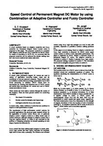
FIG. 1. The Motor Map scheme. The array of neurons maps the space V of the input patterns into the space U of the output actions.
ation the peculiarities of the segment to be controlled; it is the result of a self-organizing process within an unsupervised learning structure. Finally, the methodology developed is strictly related to hardware aspects, in order to have a complete strategy for chaos control, from the problem formulation to the analog circuit realization, able to show real-time control characteristics. The paper is organized as follows: Motor Map architecture is overviewed in Sec. II; Sec. III deals with the Motor Map controller definition; Sec. IV illustrates the details of the design of the Motor Map controller; in Sec. V some simulation results are illustrated and the discrete component based hardware implementation is presented in Sec. VI. Conclusions are drawn in Sec. VII.
II. MOTOR MAP ARCHITECTURE
The importance of topology-preserving maps in the brain relies both in the representation of sensory input signals and in the ability to perform an action in response to a given stimulus. Indeed, neurons in the brain are organized in local assemblies able to perform a given task such as, for example, sending appropriate signals to muscles. These neural assemblies constitute two-dimensional layers in which the locations of the excitation are mapped into movements. Topology-preserving structures able to classify input signals inspired the paradigm of Kohonen’s Neural Networks.13 These artificial neural networks formalize the self-organizing process in which a topographic map is created. Neighboring neurons are thus excited by similar inputs. Successful applications of these maps were in the field of pattern recognition, clustering, and so on.14 An extension of these neural structures is represented by the Motor Maps.9 These are networks able to react to localized excitation by triggering a movement 共as in the brain are the motor cortex or the superior colliculus兲. To this aim the Motor Maps, unlike the Kohonen’s networks, should include the storage of an output specific to each neuron site. This is achieved by considering two layers: one devoted to the storage of input weights and one devoted to the output weights. Figure 1 shows the scheme of a Motor Map, where the two storage spaces, relating to the input space and output space, are emphasized. It is worth remarking that the same plastic characteristics of the input layer should be preserved also in the assignment of output values. In other words, the learning phase deals with both the input weights and the output ones updating. This allows the map to perform tasks such as for example a motor control task.
Downloaded 10 Mar 2004 to 128.32.47.105. Redistribution subject to AIP license or copyright, see http://chaos.aip.org/chaos/copyright.jsp
Chaos, Vol. 12, No. 3, 2002
Chaos control by using Motor Maps
Formally, a Motor Map can be defined as an array of neurons mapping the space V of the input patterns into the space U of the output actions, ⌽:V→U.
共1兲
The learning algorithm is the key to obtain a spatial arrangement of either the input or output weight values of the map. This is achieved by considering an extension of the winner-take-all algorithm. At each learning step, when a pattern is given as input, the winner neuron is individuated: this is the neuron that best matches the input pattern. Then, a neighborhood of the winner neuron is considered and an update involving both the input weights and output ones for neurons belonging to this neighborhood is performed. Both supervised and unsupervised learning can be applied. However, in order to investigate an autonomous self-organizing system for nonlinear control, unsupervised learning has been considered. In this case there is not a priori information on the appropriate control action and no teacher is available. The algorithm should find by itself the correct control action. The only source of information is provided by the so-called Reward Function, introduced in the following, that indicates how well the control is being performed. Incidentally, both supervised learning and unsupervised learning can be considered to train the Motor Map.9 In the case of supervised learning one must know the patterns to train the network. In some cases, however, this a priori knowledge is not available and thus the more interesting unsupervised algorithm is adopted. In this case, the weight updating takes place only if the corresponding control action leads to an improvement on the controlled system; otherwise, the neuron weights are not updated. In this framework a fundamental role is assumed by the Reward Function. The definition of this function is perhaps the most crucial point in the whole network design. Since there is no direct availability of the target signal, some information is required on the effect of a given control action on the controlled system. This information has to be formalized under the form of a function of the controlled variables, the Reward Function. This has to be defined so that decreasing values lead to better control performance. More precisely, the unsupervised learning algorithm of the Motor Map can be described in the following five steps: 共1兲 In the first step the topology of the network is established. The number of the neurons is chosen and the Reward Function is established. The number of neurons needed for a given task is chosen by a trial and error strategy, thus once numerical results indicate that the number of neurons is too low, one must return to this step and modify the dimension of the map. At this step the weights of the map are randomly fixed. 共2兲 An input pattern is presented and the neuron whose input weight best matches the input pattern is established as the winner. Therefore, to establish the winner neuron, the distance between the neuron input weight and the input pattern is computed for each neuron, by considering the absolute value of the difference between these two vectors.
561
共3兲 Once chosen the winner neuron, its output weight is used to perform the control action s(t). This is not used directly, but a random variable is added to this value to guarantee a random search of the possible solutions as follows: s共t兲⫽wwinner,out⫹a s ,
共2兲
where w winner,out is the output weight of the winner neuron, a s is a parameter determining the mean value of the search step for the neuron s, and is a Gaussian random variable with zero mean. Then the increase ⌬R of the Reward Function is computed and, if this value exceeds the average increase b s gained at the neuron s, the next step 共updating of the neuron weights兲 is performed, otherwise this step is skipped. The mean increase of the Reward Function is updated as follows: bsnew⫽b sold⫹ ␥ 共 ⌬R⫺b sold兲
共3兲
where ␥ is a positive value. Moreover, a s is decreased as more experience is gained 共this holds for the winner neuron and for the neighboring neurons兲, according to the following rule: old old anew i ⫽a i ⫹ a a 共 a⫺a i 兲 ,
共4兲
where i indicates the generic neuron to be updated 共the winner one and its neighbors兲, a is a threshold for the search step to converge to, and a is the learning rate, while a takes into account that the parameters of the neurons to be updated are varied by different amounts, defining the extent and the shape of the neighborhood. 共4兲 If ⌬R⬎b s , the weights of the winner neuron and those of its neighbors are updated following the rule: w i,in共 t⫹1 兲 ⫽w i,in共 t 兲 ⫹ 共 v共 t 兲 ⫺w i,in共 t 兲兲 , w i,out共 t⫹1 兲 ⫽w i,out共 t 兲 ⫹ 共 s 共 t 兲 ⫺w i,out共 t 兲兲 ,
共5兲
where is the learning rate, v , w in , and w out are the input pattern, the input weights, and the output ones, respectively, and the index i takes into account the neighborhood of the winner neuron. In supervised learning s(t) is the target, while unsupervised learning is varied as discussed above. Steps 共2兲–共4兲 are repeated. If one wishes to preserve a residual plasticity to a later readaptation, by choosing a⫽0 in step 共3兲, the learning is ever active and so steps 共2兲–共4兲 are always repeated. Otherwise setting a⫽0 the learning phase stops when the weights converge. III. MOTOR MAPS FOR CHAOS CONTROL
As outlined in the previous section, the advantage of the use of Motor Maps for chaotic system control lies in the unsupervised learning of a nonlinear time-varying feedback gain, arising in a control architecture suitable for hardware implementation in an analog circuit. In this section the scheme of the Motor Map Controller 共MMC兲 is described with application to the control of chaotic systems. In particular, most of the examples, reported in the following, deals with the well-known Chua’s circuit; the richness of its dynamics allowed to consider it a benchmark to further validate the introduced approach.
Downloaded 10 Mar 2004 to 128.32.47.105. Redistribution subject to AIP license or copyright, see http://chaos.aip.org/chaos/copyright.jsp
562
Chaos, Vol. 12, No. 3, 2002
FIG. 2. Scheme of the Motor Map based controller. The Motor Map controls the time-varying adaptive gain multiplying the error signal on the basis only of the information of the Reward Function that is established taking into account the difference between reference system and controlled system.
For the chaos control purpose a feedback entrainment scheme is assumed. The purpose of this control is to entrain a nonlinear system to be controlled to a given trajectory. The system to be controlled is chaotic and the reference system is the same as the controlled one, but with a different parameter set, in order for example to generate a periodic orbit, i.e., a cycle limit. However, as discussed in the following, other reference trajectories 共even not properly entrainment trajectories兲 can be considered. The whole control scheme is illustrated in Fig. 2. The MMC acts on the system to be controlled by setting the value of the feedback gain. This timevarying adaptive gain modulates the error signal between the reference trajectory and the actual one and is fed back into the system to be controlled.15 Referring to the previously discussed algorithm, the main issues of the MMC design are the following: 共1兲 Reward Function selection; 共2兲 performance evaluation via software using the scheme shown in Fig. 2; 共3兲 topology optimization; 共4兲 hardware realization. These steps are outlined in the following sections. In particular, the choice of the Reward Function as regards the Chua’s circuit will be discussed in Sec. IV, although it will be shown that this choice is quite general. The section will discuss also the details of the control scheme. In Sec. V numerical simulations will be used to evaluate the performance and to reach a compromise between accuracy and number of neurons. This topology optimization is fundamental in view of the hardware implementation. The final step of the design involves the hardware realization that takes into account the previous design steps; it is illustrated in Sec. VI. IV. DESIGN OF THE MOTOR MAP CONTROLLER
As discussed above, the Motor Map learning is unsupervised. To this aim a Reward Function should be introduced. This Reward Function takes into account the Euclidean distance between the state of the system to be controlled and
Arena, Fortuna, and Frasca
one of the reference systems and thus it constitutes a performance parameter to be minimized by the adaptive controller. Even if a huge number of simulations have been carried out on different systems to be controlled, here the focus is on a double scroll Chua attractor. Several reference trajectories have been considered: a limit cycle generated by a Chua’s circuit with different parameters values, a double scroll Chua attractor and other chaotic attractors of the family of the Chua’s circuit attractors. Instead of controlling the whole state space, only two variables have been considered in the feedback; so they constitute the inputs of the MMC. Of course, the possibility to achieve good performances with this reduced state space control is not a general conclusion, but it holds for this specific chaotic attractor. However the Motor Map based control scheme is general and can include the feedback from the whole state space. The equations of the Chua’s circuit16 are the following: x˙ ⫽ ␣ 共 y⫺h 共 x 兲兲 , y˙ ⫽x⫺y⫹z, z˙ ⫽⫺  y, h 共 x 兲 ⫽m 1 x⫹0.5共 m 0 ⫺m 1 兲共 兩 x⫹1 兩 ⫺ 兩 x⫺1 兩 兲 .
共6兲
With the feedback the model becomes x˙ ⫽ ␣ 共 y⫺h 共 x 兲兲 ⫹k x 共 x ref⫺x 兲 , y˙ ⫽x⫺y⫹z⫹k y 共 y ref⫺y 兲 , z˙ ⫽⫺  y⫹k z 共 z ref⫺z 兲 , h 共 x 兲 ⫽m 1 x⫹0.5共 m 0 ⫺m 1 兲共 兩 x⫹1 兩 ⫺ 兩 x⫺1 兩 兲 ,
共7兲
where x ref , y ref , and z ref are the state variables of the reference system. As previously outlined, only two variables have been fed back, namely, in our simulations k z was set to zero and not allowed to vary. Moreover it will be shown in the experimental results presented in Sec. VI that also the choice of k y ⫽0, k x ⫽0, and k z ⫽0 leads to good results. The Reward Function has been chosen as the square of the Euclidean distance between the two controlled state variables and the corresponding reference ones as follows: R⫽⫺ 共共 x⫺x ref兲 2 ⫹ 共 y⫺y ref兲 2 兲 .
共8兲
Two schemes have been used to perform the control. In the former one a generic case is assumed: a Motor Map is built for each variable to be controlled. In the second scheme a unique Motor Map acts on the system controlling the variable having the largest error. In the former scheme, the two Motor Maps act independently onto the two state variables x and y, by storing in the input layer the values of the corresponding input pattern and in the output one the values of the corresponding adaptive feedback gain k x for the first map or k y for the second map. Instead, in the second scheme only one Motor Map is devoted to control both of the two variables, by controlling at each step that one having the largest error. In both cases the winner-take-all law establishes which
Downloaded 10 Mar 2004 to 128.32.47.105. Redistribution subject to AIP license or copyright, see http://chaos.aip.org/chaos/copyright.jsp
Chaos, Vol. 12, No. 3, 2002
Chaos control by using Motor Maps
563
over, this assumption is in some sense justified by the low number of neuron needed for the task. In the Motor Map implemented the learning rate was kept constant. In fact, while in supervised learning schemes the learning rates, in Eqs. 共5兲, can be gradually decreased to stop the learning phase, in unsupervised learning schemes the learning rate is usually kept constant. Keeping the learning rate constant enables a continuous learning for the Motor Map and makes it able to deal with changes in the reference trajectory. On the other hand, this can lead to instabilities in the value of the feedback gain. In fact, simulations carried out reveal ever increasing values of the feedback gain k. To eliminate this drawback a performance goal on the error is introduced in the Motor Map, namely, when the error is under a given bound, the learning is stopped. This avoids a dependence on the time of the learning rate (t) and also provides a mechanism to restart the learning when the error is over the given bounds. Moreover, the achievement of this goal constitutes a performance parameter for the Motor Map. To reduce hardware requirements, by exploiting the noiselike behavior and the broadband spectrum of a chaotic attractor, it can be assumed that the stochastic term is implemented by a chaotic signal from an analog circuit. In particular, it can be chosen a zero-mean variable as for example the y variable of another Chua’s circuit. In order to make sense the hypothesis of broadband spectrum, this chaos generator Chua’s circuit should have time constants smaller than the ones of the circuit to be controlled. Simulation results emphasized the role played by the variance of this signal; the settling time depends on this variance, small increases of the variance, by multiplying this signal by a gain factor, lead to smaller values of the settling time. This consideration can be useful to decrease the settling time, by considering the parameter a s in Eq. 共2兲 as a function of the actual error, and providing a high value when the error is large and a low value when the error is small. Thus a s is not updated as in Eq. 共4兲, but it is function of the actual error. Moreover, the assumption, that the Motor Map has the same time constant as the system to be controlled, can be unrealistic in a hardware realization. To analyze the MMC performance in the real case, simulations in the case when the signal to be controlled is faster than the learning rate of the Motor Map have been also performed, showing the good capabilities of the MMC.
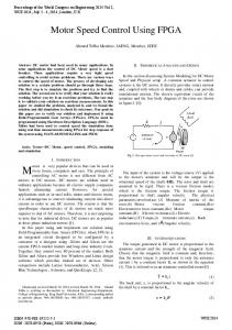
FIG. 3. Tracking of a limit cycle with 2 MMCs 共each MMC independently acts on a variable of the controlled system兲: 共a兲 trend of the variable x of the controlled system and of the variable x ref of the reference system; 共b兲 limit cycle of the controlled system 共solid line兲 and of the reference system 共dashed line兲; 共c兲 errors and error bounds for both the x and y variables. The errors are in the admissible error bounds after a short transient in which the MMCs learn the control actions.
neuron has the most suitable gain value. Moreover, only the weights of the winner neuron are updated. This assumption leads to a simpler hardware realization than the case when a neighborhood of the winner neuron is also updated. More-
V. SIMULATION RESULTS
In this section a number of control examples are dealt with and simulation results are presented. Both the control schemes previously outlined are considered: the first one based on two independent Motor Maps acting on two state variables of the Chua’s system as in Eq. 共7兲, the second one based on a unique Motor Map able to furnish either k x or k y and acting on the variable having the largest error. The system to be controlled is, in the most simulations performed, the double scroll Chua attractor in Eqs. 共7兲 with
Downloaded 10 Mar 2004 to 128.32.47.105. Redistribution subject to AIP license or copyright, see http://chaos.aip.org/chaos/copyright.jsp
564
Chaos, Vol. 12, No. 3, 2002
Arena, Fortuna, and Frasca
FIG. 4. Switching of the reference trajectory: 共a兲 trend of the variable x of the controlled system and of the variable x ref of the reference system; 共b兲 absolute value of the error x ref⫺x and error bound; 共c兲 winner neuron vs learning epochs. The parameters of the reference system are changed so that the behavior changes from a chaotic double scroll Chua’s attractor to a limit cycle and then again to the double scroll. Part 共c兲 shows that only two neurons are involved in controlling the system when the reference is a limit cycle 共the activated neurons alternatively are the neuron 1 and neuron 3兲, while tracking the chaotic reference requires more neurons.
the following parameter values:
␣ ⫽9,  ⫽14.286, m 0 ⫽⫺ 17 , m 1 ⫽ 72 .
共9兲
As discussed above, an Error Bound 共EB兲 on the steady
state error between the reference and the controlled system for each of the controlled variables has been considered as performance specification to establish the end of the learning. Moreover, the definition of settling time has been adapted from Ref. 17 as the time 共in epochs兲 for the output response to reach and thereafter remain within the error bound. First, the control scheme with two Motor Maps, called in
Downloaded 10 Mar 2004 to 128.32.47.105. Redistribution subject to AIP license or copyright, see http://chaos.aip.org/chaos/copyright.jsp
Chaos, Vol. 12, No. 3, 2002
Chaos control by using Motor Maps
565
␣ ⫽7,  ⫽12, m 0 ⫽⫺ 17 , m 1 ⫽ 72 .
共10兲
Two maps, each having 4 neurons, have been trained for 390 epochs to achieve the performance specifications EBx ⫽0.08 共error bound for the x variable兲 and EBy ⫽0.04 共error bound for the y variable兲. The performance goals were met with settling time t sx ⫽517 epochs and t sy ⫽590 epochs. Figure 3共a兲 shows the trends of the variable x of the controlled system and of the variable x ref of the reference system, while the phase planes x⫺y for both the two systems are shown in Fig. 3共b兲. Figure 3共c兲 shows the error and the EBs for the x and y variables. From these results it is clear that the Motor Map learns efficiently by itself the control action to be performed on the system to be controlled. B. Example 2: Switching of the reference with the 2 MMCs scheme
FIG. 5. Tracking of a double scroll with 1 MMC: 共a兲 double scroll of the controlled and reference system 共solid and dashed line, respectively兲; 共b兲 the x state variable 共controlled system兲 vs the x ref variable 共reference system兲, the 45° line indicates that the two chaotic circuits, starting from different initial conditions, synchronize; 共c兲 trend of the gain k x .
the following the 2 Motor Maps Controllers 共2 MMCs兲 scheme, has been considered. A. Example 1: Tracking of a limit cycle
As a first example a limit cycle has been chosen as entrainment trajectory for the system 共7兲. This limit cycle is generated by choosing the parameters of the system 共6兲 as follows:
A further example illustrates how the self-organizing structure is able to deal with different reference trajectories. In particular, the case in which a double scroll Chua attractor with parameters 共9兲 alternates with a limit cycle as in 共10兲 as an entrain trajectory for the system. This example is illustrated in Fig. 4; the controller is constituted by two Motor Maps, each one having 9 neurons, trained for 10 000 epochs. The reference system, initially a double scroll Chua attractor, is switched to a limit cycle at t⫽3800 epochs and comes back to a double scroll Chua attractor at t⫽5500 epochs. In Fig. 4共a兲 the trend of the variable x of the controlled system is shown also with the reference signal x ref . As it can be noticed the Motor Map learns the right control action within the first 1000 epochs and the two signals are indistinguishable until the switching of the reference. When the limit cycle is assumed as reference trajectory, the error increases as shown in Fig. 4共b兲, but remains within low bounds. Of course, this takes place since the map has to completely reorganize to track the new trajectory. Figure 4共c兲 shows also a signal indicating the winner neuron of the first map, whose output constitutes the k x , chosen to actively perform the control action. Each of the discrete values that this signal can assume indicates a different neuron of the map: two of the 9 neurons of the map 共the one referring to the x variable兲 are invoked to control the system when the reference is a cycle limit, while, when the system is entrained to the double scroll, four neurons are needed. In Fig. 4共c兲 these neurons are consecutively labeled. C. Example 3: The 1 MMC scheme
In the case of the scheme with a single Motor Map, as intuition suggests, the achievement of the performance specifications is more difficult. In this experiment the controller chooses to control the variable having the largest error from the reference one. In this case, once completed the learning phase, results show that a cluster of neurons will be devoted
Downloaded 10 Mar 2004 to 128.32.47.105. Redistribution subject to AIP license or copyright, see http://chaos.aip.org/chaos/copyright.jsp
566
Chaos, Vol. 12, No. 3, 2002
Arena, Fortuna, and Frasca
FIG. 6. Tracking of chaotic orbits with 1 MMC: 共a兲 the reference is a single scroll; 共b兲 the reference is a chaotic attractor as in 共12兲.
to the control of a variable, while another cluster will control the other variable. Simulations also indicate that in general the settling time increases. Figure 5 illustrates an example of the scheme with a single Motor Map with 9 neurons. In this case the reference trajectory is a double scroll as in Eq. 共9兲 as the controlled one, but with different initial conditions. Figure 5共a兲 shows the phase plane for both the reference system 共dashed line兲 and the controlled one 共solid line兲. The control law compensates the effects of the sensitive dependence of the chaotic dynamics to the initial conditions and, after a transient phase, guarantees a low error. Figure 5共b兲 depicts the x trend versus the reference variable x ref ; the 45° line shows the matching between the two variables. Figure 5共c兲 illustrates the trend of
the feedback gain k x ; the sudden oscillations in the gain take place when the winner neuron changes. This last control example strictly resembles the chaos synchronization issues.18 There the target is to make a slave system to show the same chaotic dynamics as a master one. However, the two approaches are different, since the MMC scheme is quite insensitive to changes in the parameters of the slave system. D. Example 4: Tracking of chaotic orbits with 1 MMC
In Fig. 6 other examples of the Motor Map adaptive control are shown. In Fig. 6共a兲 the trajectory reference is the single scroll with the following parameters:
FIG. 7. Controlling a Lorenz system with a limit cycle reference generated by a Chua’s circuit: 共a兲 the original strange attractor of the Lorenz system; 共b兲 reference system and controlled Lorenz trajectory.
Downloaded 10 Mar 2004 to 128.32.47.105. Redistribution subject to AIP license or copyright, see http://chaos.aip.org/chaos/copyright.jsp
Chaos, Vol. 12, No. 3, 2002
Chaos control by using Motor Maps
567
FIG. 8. Scheme of the neuron circuit. The blocks in the dashed boxes represent: B 1 the input buffer, B 2 the input weight storage stage, B 3 the output weight storage stage, B 4 the stage performing the difference 共in absolute value兲 between the input signal and the input weight value representing a matching between the input pattern and the neuron and needed to determine the neuron that best matches the input pattern.
␣ ⫽8.5,
␣ ⫽⫺6.691 91,
 ⫽14.286,
 ⫽⫺1.520 61,
m 0 ⫽⫺ 17 ,
m 0 ⫽⫺ 17 ,
m 1 ⫽ 72 .
共11兲
In Fig. 6共b兲 another chaotic attractor generated by a Chua’s circuit with the following parameters:
m 1 ⫽ 72 ,
共12兲
was chosen as a reference system. In both cases of Figs. 6共a兲 and 6共b兲 the controlled system is the double scroll Chua attractor and the Motor Map has 9 neurons.
FIG. 9. Scheme of the reward circuit. The circuit implements Eq. 共16兲 and returns as an output to a signal representing the sign of the derivative of Eq. 共16兲. An analog multiplier 共AD633兲 is cascaded by a derivator stage and a Schmitt trigger.
Downloaded 10 Mar 2004 to 128.32.47.105. Redistribution subject to AIP license or copyright, see http://chaos.aip.org/chaos/copyright.jsp
568
Chaos, Vol. 12, No. 3, 2002
Arena, Fortuna, and Frasca
FIG. 10. Scheme of the Chua’s circuit realized by Cellular Nonlinear Networks.
E. Example 5: Control of the Lorenz system
Finally, an example of the control of another chaotic system, the Lorenz system,19 is briefly discussed. The equations of the Lorenz system, including the feedback signals, are
⫽10, b⫽ 83 ,
x˙ ⫽ 共 y⫺x 兲 ⫹k x 共 x ref⫺x 兲 ,
r⫽28,
y˙ ⫽rx⫺y⫺xz⫹k y 共 y ref⫺y 兲 , z˙ ⫽⫺bz⫹xy⫹k z 共 z ref⫺z 兲 .
of a Chua’s circuit with parameters as in 共10兲, thus x ref , y ref , and z ref refer to this Chua’s system. The parameters of the Lorenz system have been chosen as follows:
共13兲
The reference trajectory is generated by the limit cycle
共14兲
in order to have the well known strange attractor with the butterfly pattern, shown in Fig. 7共a兲. The MMC is constituted by a Motor Map with 16 neurons. Figure 7共b兲 shows the
FIG. 11. Trends of the z state variable of the controlled circuit and the reference one from SPICE simulation. The parameters of the reference system are changed so that it alternatively behaves periodically or chaotically.
Downloaded 10 Mar 2004 to 128.32.47.105. Redistribution subject to AIP license or copyright, see http://chaos.aip.org/chaos/copyright.jsp
Chaos, Vol. 12, No. 3, 2002
Chaos control by using Motor Maps
569
FIG. 12. Self-organization of the neurons of the Motor Map controller 共SPICE simulation兲. The trends of the input weights are shown also with the x variable for both reference and controlled system. w in,2 follows the negative part of the signal, indicating that for that range of input values, neuron 2 is the winner neuron. The other two neurons deal with other input ranges. The reference is assumed varying as in Fig. 11.
results achieved by setting k z ⫽0, in this case the trajectory of the controlled system does not follow exactly the reference one; a feedback on the z variable is needed to achieve the exact matching of the two trajectories. In this last example and as well as in the other ones discussed in this paragraph, the reference trajectory is generated by a system with very different dynamics. The control performance is still good. VI. HARDWARE REALIZATION
In this section the design of a fully analog hardware realization of the MMC is illustrated. The realization takes into account the two Motor Maps scheme to control a Chua’s circuit by assuming as a reference either a double scroll Chua attractor or a limit cycle. In both the cases the circuit to be controlled is chaotic. In the previous section the learning algorithm was reported in the same way as it was implemented by software to provide simulation results. The focus of this analog hardware control is to implement the learning phase in the simplest way, compatibly with the quality of the results. This is required by the need of having the simplest circuit topology. The Motor Map circuit is essentially constituted by three functional blocks: the array of neurons, the comparator establishing the winner neuron, and the circuit implementing the Reward Function. Each neuron of the map includes two capacitors devoted to storing the input weight and the output one, respectively. In order to design a completely analog Motor Map, Eqs. 共5兲 must be rewritten in a continuous form, dw i,in ⫽ 共 v ⫺w i,in兲 , dt dw i,out ⫽ 共 s⫺w i,out兲 . dt
共15兲
At this point some simplification on the algorithm simulated are added in order to reach a good compromise between
the hardware complexity and the result suitability. The learning rate is kept constant ( ⫽1/ ), where is the time constant of the neuron circuit, while the is assumed to be unitary. This means to adopt a winner-take-all strategy, simplifying the hardware for the learning phase. Moreover, the hardware realization of the Motor Maps allows to have an efficient adaptive control device, which continuously adapts ever increasing the learning efficiency, in spite of sudden changes in the reference signal. This learning on-line characteristics is realized though a continuous updating of the capacitor voltages. The neuron circuit is reported in Fig. 8. The input and output weights are stored in two capacitors. The capacitor C 1 stores the input weight, while the capacitor C 2 stores the output weight. Each of these capacitors is cascaded by a buffer 共block B 2 and B 3 , respectively兲. A MOS device for each block B 2 and B 3 allows the updating of the weight capacitor. The signal IN is the input signal, that is one of the state variables of the circuit to be controlled. A buffer (B 1 ) avoids load problems for this input. The other input signal, indicated in Fig. 8 as f orza, corresponds to s(t). The MOS devices M1 and M2 are enabled only when both the signals winner and rew take high values, namely when this neuron was selected as the winner and the reward, defined in 共8兲, is increasing. This condition allows the updating of the input and output weights. The signals provided by the neuron circuit are the two weights and the signal dist 共block B 4 ). This signal is used to determine the neuron that best matches the input pattern. It is obtained by using a comparator cascaded by a precision rectifier20 as illustrated in Fig. 8. When a new input pattern is considered, the comparison between the weight value and the input signal IN takes place in each neuron. Thus the neuron furnishes the signal dist that is proportional to the difference between the input weight and the input signal. The winner neuron is established by a comparator block for all these signals. With respect to the Motor Map depicted in Sec. III, the
Downloaded 10 Mar 2004 to 128.32.47.105. Redistribution subject to AIP license or copyright, see http://chaos.aip.org/chaos/copyright.jsp
570
Chaos, Vol. 12, No. 3, 2002
Arena, Fortuna, and Frasca
FIG. 13. Experimental results: 共a兲 trends of the signals x ref 共lower trace兲 and x 共upper trace兲 when the Motor Map controller is not active; 共b兲 trends of the signals x ref 共lower trace兲 and x 共upper trace兲 when the Motor Map acting on the x variable is active; 共c兲 trends of signals y ref 共lower trace兲 and y 共upper trace兲 when the Motor Map controller is active; 共d兲 trends of signals x ref 共lower trace兲 and x 共upper trace兲 when the Motor Map controller is active; 共e兲 x vs x ref when the controller is on.
reward block presents some differences. Instead of assuming only the Reward Function 共8兲, two independent Reward Functions have been considered for the two Motor Map controllers, measuring the distance between the variable to be
controlled and the corresponding reference one. Moreover, the reward block establishes if the weights of the winner neuron should be updated or not. While in simulation the winner neuron is updated by taking into account
Downloaded 10 Mar 2004 to 128.32.47.105. Redistribution subject to AIP license or copyright, see http://chaos.aip.org/chaos/copyright.jsp
Chaos, Vol. 12, No. 3, 2002
Chaos control by using Motor Maps
571
FIG. 14. Experimental results. The reference signal is generated by a single scroll Chua attractor: 共a兲 trends of x ref 共lower trace兲 and x 共upper trace兲; 共b兲 x vs x ref .
the average increase 关 b s in Eq. 共3兲兴 gained at the lattice site of the winner neuron, in the hardware realization the updating occurs when the derivative of the Reward Function is positive: being the Reward Function 共8兲 ever negative, this corresponds to minimize the error between the circuit and the reference. The reward circuit, reported in Fig. 9, implements both the Reward Function and the differentiator block. Thus the equation implemented by the reward block, for example the one relating to the x state variable, is the following: ⌬R⫽⫺
d 共 x⫺x ref兲 2 . dt
共16兲
It should be noticed that, since it is important only to establish if the reward is increasing or is decreasing, a Schmitt trigger block cascades the differentiator block. Therefore, the output signal rew of the reward block is saturated at the high value when the error is decreasing; this signal is then used to enable the updating of the winner neuron. The Chua’s circuit realization has been developed by using the Cellular Nonlinear Networks approach as introduced in Ref. 21. The circuit is reported in Fig. 10. The results reported in the following have been obtained by using two Motor Maps, each one with 3 neurons, acting on the state variables of a Chua’s circuit as in 共7兲. The control signals act on the state variable x and z, and k y was set to zero. The parameters for the circuit to be controlled have
been assumed as in 共9兲, while the limit cycle used as a reference was obtained by assuming the parameters as in 共10兲. SPICE simulations have been performed by considering as reference system a Chua’s circuit whose parameters are changed every 20 ms in order to show the adaptive capabilities of the control. Thus, the limit cycle and the double scroll Chua attractor alternates every 20 ms. Figure 11 shows the result of such a SPICE simulation. As it can be noticed, at t⫽20 ms the reference changes from a periodic signal to a chaotic signal and then at t⫽40 ms it changes again from chaotic to periodic behavior. In both cases the control error is small. The self-organization of the three neurons is clear from the analysis of Fig. 12; the three neurons are activated for different ranges of the reference signal. In fact, w in,1 loses competition for signals beyond an interval around 0 V, but inside this range it provides the control action. w in,2 is specialized to follow the negative part of the signal, while w in,1 the positive part. A network with more neurons than this one should reveal a high decomposition of the reference signal in amplitude bounds and a more efficient control action in terms of gain amplitude, but a more complicated hardware is required. In Figs. 13 and 14 experimental results are shown. In Fig. 13共a兲 the trends of the state variable x 共upper trace兲 and the reference x ref 共lower trace兲, when the control is not active, are shown: the two chaotic systems evolve indepen-
Downloaded 10 Mar 2004 to 128.32.47.105. Redistribution subject to AIP license or copyright, see http://chaos.aip.org/chaos/copyright.jsp
572
Chaos, Vol. 12, No. 3, 2002
dently. In Fig. 13共b兲 only the Motor Map acting on the x variable is active, while the Motor Map acting on the z variable is switched off. In Fig. 13共d兲 the trends of the variable x and the reference signal x ref are shown when both the Motor Maps are switched on, while in Fig. 13共e兲 x vs x ref is shown and in Fig. 13共c兲 the variable y and the corresponding variable y ref of the reference system are shown when both the Motor Maps work. Figure 14 deals with the case in which the reference system is a single scroll Chua attractor; even in this case, the Motor Map controller offers good performances.
VII. CONCLUSIONS
In this paper a Motor Map based adaptive controller has been introduced to entrain a chaotic system to a trajectory generated by another attractor 共both a limit cycle and other strange attractors have been analyzed as reference trajectories兲. A feedback entrainment scheme has been used, in which the feedback signal is multiplied by a time-varying gain, generated by the Motor Map. This scheme provides an adaptive control that does not need a priori information on the controlled dynamics. In fact, the appropriate control action is learned on-line trough reinforcement: the effects of the control law on the controlled system are evaluated by the Reward Function; the learning is therefore effectively accomplished by taking into account only those actions leading to an improvement in the closed loop performance. The design of the Motor Map Controller involves only the choice of the Reward Function and the number of neurons. Both of the steps are straightforward: as Reward Function the Euclidean distance between the state of the reference and that one of the controlled system was adopted and the choice of the number of neurons was accomplished by trial and error. Therefore, the key feature of this approach is a time-varying self-learning control law, able to adapt on-line even when the reference dynamics undergoes sudden variations. The approach is also quite general, since it does not depend on the controlled system. Of course, the limit of the approach is met when, due to a great difference between the reference and controlled dynamics, the gain required to achieve the control goal is greater than the network saturation levels. In the first part of the paper some results from a huge number of simulations performed have been presented. In most of the simulations the system to be controlled was a Chua’s circuit and the feedback of only two state variables was successfully applied. The results obtained emphasize the capabilities of the Motor Map to learn by itself the control action even when the reference attractor is switched into another one. Steady state errors have been considered as specifications for the system. The correspondent settling times have been used to compare the performances of a scheme based on two Motor Maps 共each one acting on a state variable兲 and the performance of the scheme based on a single Motor Map 共acting on the variable having the largest error兲. In the second case the neurons cluster to deal with the two state variables. This second case, even if the settling time is greater than in the first case, is particularly interesting since
Arena, Fortuna, and Frasca
it requires only one Motor Map to perform the control of the chaotic system. In the second part of the paper the design of an analog electronic realization has been presented as well as some experimental results. This has been possible since SPICE simulation results indicated that a low number of neurons is needed to perform the task of chaos control. This consideration also with other simplifications of the original Motor Map learning algorithm, as, for example, that no cooperation exists in the small assembly of neurons, leads to the feasibility of the hardware implementation. Moreover, the experimental results agree with simulations. The application of Motor Maps to chaotic system control gave very efficient results. Moreover, the Motor Map learns in an unsupervised manner the adaptive control law without any information on the structure of the controlled system. This is extremely important, since most of the traditional nonlinear control methods cannot neglect the system knowledge, while traditional supervised neural approaches need a teaching input that sometimes is not available. It has been experimentally proven that the considered application is straightforward and opens the way to the use of Motor Maps as extremely robust nonlinear adaptive controllers for uncertain systems. 1
G. Chen and X. Dong, From Chaos to Order: Methodologies, Perspective and Applications, World Scientific Series on Nonlinear Science, Series A 共World Scientific, Singapore, 1998兲, Vol. 24. 2 Y. Braiman and I. Goldhirsch, ‘‘Taming chaotic dynamics with weak periodic perturbations,’’ Phys. Rev. Lett. 66, 2545–2548 共1991兲. 3 E. A. Jackson and A. Hu¨bler, ‘‘Periodic entrainment of chaotic logistic map dynamics,’’ Physica D 44, 407– 420 共1990兲. 4 E. A. Jackson, ‘‘Controls of dynamics flows with attractors,’’ Phys. Rev. A 44, 4839– 4853 共1991兲. 5 G. Chen and X. Dong, ‘‘On feedback control of chaotic continuous-time systems,’’ IEEE Trans. Circuits Syst., I: Fundam. Theory Appl. 40, 591– 601 共1993兲. 6 M. P. Golden and B. E. Ydstie, ‘‘Small amplitude chaos and ergodicity in adaptive control,’’ Automatica 28, 11–25 共1992兲. 7 S. Boccaletti, C. Grebogi, Y.-C. Lai, H. Mancini, and D. Maza, ‘‘The control of chaos: Theory and applications,’’ Phys. Rep. 329, 103–197 共2000兲. 8 E. A. Jackson, ‘‘The OPCL control method for entrainment, modelresonance, and migration actions on multiple-attractor systems,’’ Chaos 7, 550–559 共1998兲. 9 H. Ritter, T. Martinetz, and K. Schulten, Neural Computation and SelfOrganizing Maps 共Addison–Wesley, Reading, 1992兲. 10 K. J. Hunt, D. Sbarbaro, R. Zbikowski, and P. J. Gawthrop, ‘‘Neural networks for control systems: A survey,’’ Automatica 28, 1083–1112 共1992兲. 11 S. I. Mistry, S.-L. Chang, and S. S. Nair, ‘‘Indirect control of a class of nonlinear systems,’’ IEEE Trans. Neural Netw. 7, 1015–1023 共1996兲. 12 A. S. Poznyak, W. Yu, E. N. Sanchez, and J. P. Perez, ‘‘Nonlinear adaptive trajectory tracking using dynamic neural networks,’’ IEEE Trans. Neural Netw. 10, 1402–1411 共1999兲. 13 T. Kohonen, ‘‘Self-organized formation of topologically correct feature maps,’’ Biol. Cybern. 43, 59– 69 共1972兲. 14 T. Kohonen, Self-Organization and Associative Memory 共Springer-Verlag, Berlin, 1989兲. 15 P. Arena, M. Bucolo, L. Fortuna, and M. Frasca, ‘‘Motor map for nonlinear control,’’ 6 th Experimental Chaos Conference, July 22–26, Potsdam, Germany, 2001. 16 R. N. Madan, Chua’s Circuit: A Paradigm for Chaos, World Scientific Series on Nonlinear Sciences, Series B 共World Scientific, Singapore, 1993兲, Vol.1. 17 J. D’Azzo and C. H. Houpis, Linear Control Systems Analysis and Design 共McGraw-Hill, New York, 1995兲.
Downloaded 10 Mar 2004 to 128.32.47.105. Redistribution subject to AIP license or copyright, see http://chaos.aip.org/chaos/copyright.jsp
Chaos, Vol. 12, No. 3, 2002 18
L. M. Pecora and T. L. Carrol, ‘‘Synchronization in chaotic systems,’’ Phys. Rev. Lett. 64, 821– 824 共1990兲. 19 S. H. Strogatz, Nonlinear Dynamics and Chaos 共Perseus, New York, 2001兲.
Chaos control by using Motor Maps
573
J. Millman and A. Grabel, Microelectronics 共McGraw-Hill, New York, 1989兲. 21 G. Manganaro, P. Arena, and L. Fortuna, Cellular Neural Networks: Chaos, Complexity, and VLSI Processing 共Springer-Verlag, Berlin, 1999兲. 20
Downloaded 10 Mar 2004 to 128.32.47.105. Redistribution subject to AIP license or copyright, see http://chaos.aip.org/chaos/copyright.jsp