Available online at www.sciencedirect.com
ScienceDirect Procedia Engineering 144 (2016) 94 – 101
12th International Conference on Vibration Problems, ICOVP 2015
Vibration Control using BCW Induction Motor Gaurav Kumara, Karuna Kalitaa* a
Indian Institute of Technology Guwahati, Guwahati-781039, India
Abstract A small amount of asymmetry of the magnetic flux in the air-gap of an electrical machine can create a considerable amount of force called unbalanced magnetic pull (UMP). This unbalanced magnetic pull is generated due to the presence of the magnetic fields of pole pair p and p±1 in the air gap of the motor. A torque producing magnetic field of pole pair p is already present due to the main supply of the stator winding. To create a controllable UMP an additional magnetic field of pole pair p±1 can be generated using an additional stator winding. This controllable UMP can be used for active vibration control. The present paper uses a special type of winding scheme called bridge configured winding (BCW) where a single set of winding can be used to generate magnetic field of pole pair p+1 and p-1. An experimental setup has been developed to demonstrate the vibration control using isolated bridge supply of a BCW based induction motor by controlling the additional magnetic field of pole pair p+1 and p-1. © 2016 2016The TheAuthors. Authors. Published by Elsevier © Published by Elsevier Ltd. Ltd. This is an open access article under the CC BY-NC-ND license (http://creativecommons.org/licenses/by-nc-nd/4.0/). Peer-review under responsibility of the organizing committee of ICOVP 2015. Peer-review under responsibility of the organizing committee of ICOVP 2015 Keywords: BCW; Induction Motor; Vibration; Control.
1. Introduction Rotor vibration and its control is one of the major challenges for the machineries used in the power industry. The requirement of electrical motors in general and induction motors in particular are ever increasing. So, if we can control the vibration with the help of motor itself, which is the source of the rotational energy, then it can solve our purpose. The sum of the total forces between the rotor and the stator is zero in case of a concentric rotor. However if the rotor is moved from the center point the magnetic field of the motor is disturbed. When the rotor is displaced from the center due to the external effect or due to the unbalance present in the system, the magnetic flux in the air gap is distorted and a net force is generated. This force is known as unbalanced magnetic pull (UMP) and is exerted on the rotor. Alexander and Pertsch [1] wrote a review paper on dynamo electric machines. From this paper it has been found
* Corresponding author. Tel.: +91-361-2582680. E-mail address:
[email protected]
1877-7058 © 2016 The Authors. Published by Elsevier Ltd. This is an open access article under the CC BY-NC-ND license
(http://creativecommons.org/licenses/by-nc-nd/4.0/). Peer-review under responsibility of the organizing committee of ICOVP 2015
doi:10.1016/j.proeng.2016.05.011
Gaurav Kumar and Karuna Kalita / Procedia Engineering 144 (2016) 94 – 101
out that Fisher-Hinnen (1899) [1]gave the first formula for the UMP for his dynamo design. Behrend (1900)[1] gave a mathematical discussion of the case of a machine with a very large number of poles and derives the formula for UMP calculation. Rey (1904)[1] has shown that Beherend’s and Fisher-Hinnens formulas are not consistent and sets out to derive a new formula, especially applicable to induction motors with eccentric rotor. Nomenclature BCW UMP FFT
bridge configured winding unbalanced magnetic pull fast fourier transform
Rosenberg [2] investigated the occurrence and the effect of UMP in electrical machines and derived simple practical formulas. His calculations are based on difference in the flux densities on opposite side of the air gap and developed the equations on graphical basis from the saturation curve. Rosenberg could not explain the reason of production of UMP. Later in 1919 Stiel first showed that origin of the UMP is due to harmonic fields in the air gap. Hildebrand [3] is the first to tabulate all the known possible harmonic fields. Robinson [4] again used saturation curve and considered the effect of saturation, parallel paths in the stator winding and primary reactance. He gave the formula for UMP for a constant displacement of 1/32 inch. Fronhe [5] used analytical method instead of graphical method to add the saturation effect for the UMP calculation. He also considered damper winding and proved that effective damping is possible only with short-circuited windings arranged in the stator. The present work is based on a single set of winding scheme which has parallel branches with equalizing connections. Debortoli et al. [6] and Tenhunen [7,8] used a transient finite element model to study the effect of rotor eccentricity, parallel paths and equalizing currents on UMP. They noticed that the amplitude of the force can be reduced by the equalizing connection and it can change the direction of force opposite to the direction of the shortest air gap. Chiba et al. [9] introduced the dual set of winding scheme. They proposed a conventional winding scheme with four pole winding for torque production and a two pole winding for generating the radial magnetic force to control the UMP. Laiho et al. [10] developed a built in force actuator for active control of rotor vibration in cage induction electrical machine. A single set of winding also known as Bridged Configured Winding, which has equalizing connection in the parallel branches, proposed by Khoo [11] can be used for both torque as well as radial force production. Khoo et al. [12] demonstrated the capability of producing controllable transverse force by using BCW in a three phase 1.1kW brushless permanent magnet motor. Kalita and Laiho [13] developed an analytical expression for calculation of lateral force in the air gap in bridge configured induction motor. Natesan et al. [14] implemented the BCW in a three phase four pole induction machine for the detection of unbalance present in the system. The equalizing currents or bridge currents flow due to unbalance present in the system. They demonstrated that the equalizing current or bridge current can be used as a measure of unbalance present in the system. There are two types of UMP, one which is generated due to the eccentric rotor motion and one which is generated purposefully to control the UMP generated by the eccentric rotor motion. UMP is produced due to the presence of additional field of one-pole pair difference compared to the main field. So, to produce UMP we will have to generate additional field of one pole-pair difference from main field. In this work the bridge-configured winding scheme proposed by Khoo [10] is used to produce torque as well as the transverse force. Fig. 2(a) shows the winding scheme of the distributed, double layered, chorded winding and Fig. 2(b) shows the bridge configured based winding circuit. The windings are connected in series and the currents are supplied in two parallel paths. Additional currents or voltages can be supplied through the switches S1, S2 and S3 shown in Fig. 2 (b). These bridge currents will develop an additional two-pole magnetic field which is of one-pole pair difference compared to the main field. The principal feature of the bridge configured winding is that the currents responsible for torque production are divided into two parallel paths in each phase. However, it is mandatory that an appropriate isolation between the levitation supply and the mains must be enforced for the bridge connection to work properly [11]. In the present work the capability to produce controllable transverse force in a BCW based 4-pole induction motor has been exploited by controlling the voltage across the bridge point of the winding. An experimental setup has been built and the voltage across the bridges has been controlled externally using a developed controller.
95
96
Gaurav Kumar and Karuna Kalita / Procedia Engineering 144 (2016) 94 – 101
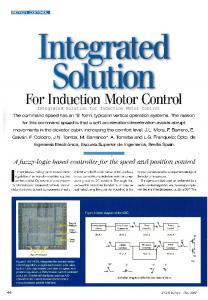
2. System Details The experimental setup consists of mainly two parts, a modified three phase, 4-pole 37 kW induction machine and a controller to generate required amount of potential difference across the bridge point. The original winding of the induction machine has been replaced by a 4-pole bridge configured winding. Two proximity sensors have been used to measure the rotor responses in x and y - directions. Current and voltage transducers have been used to measure the currents and the voltages across the bridges. The shaft is supported by two external mechanical bearings at both the ends. A backup bearing has been installed at the end-shield cover plate near the driving end side of the motor for safety purposes. This backup bearing has a clearance of 0.5mm. Fig. 1 shows the developed experimental setup, Fig. 2(a) shows the double layered bridge configured winding and Fig. 2(b) shows the circuit diagram.
Fig. 1. A modified 37kW Induction machine 1 - Bearing Housing at ND end, 2 - Bearing Housing at D end, 3 - Test Machine, 4 - Perforated Disc, 5 – Location 1 for the rotor response near to the D-End bearing, 6 – Location 2 for the rotor response near to the end shield cover plate and 7 - Location 3 for the rotor response near to the ND-End bearing, 8- Panel board
b a
Fig. 2. A BCW winding scheme (a) distributed double layered winding, (b) winding circuit
Gaurav Kumar and Karuna Kalita / Procedia Engineering 144 (2016) 94 – 101
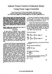
3. Experimental Investigation Whenever there is a potential difference present at the bridge point, the rotor vibrates. So, the aim is to study the bridge voltages and means to control it. To understand the effect of the voltage difference across the bridge point of the winding on the rotor vibration, bridge voltage has been studied in different cases and rotor vibration has been controlled by controlling the bridge voltage across the bridge point of the winding. Voltage has been supplied in different combinations and simultaneously rotor displacements and bridge voltage across bridge points have been measured. Used Copley amplifier has inbuilt PID controller and its gain has been set in such a way that 1 volt of reference signal generates output of 3.25 volt. The characterization of the controller has been done while keeping the motor in OFF condition and a reference input signal has been given using data acquisition system and the output across the bridges of the winding has been measured. The measurement of voltages and displacements has been done using voltage transducers (LEM make LV 20-P) and proximity sensors (GE’s Bently Navada make 3300 XL NSv). 3.1. Case – I, Study of Bridge Voltages and Rotor Vibration when Bridge is OFF and ON conditions The potential difference is developed across the bridge points due to the eccentric motion of the rotor. The frequency of the main supply voltage of the motor is kept at 40 Hz and bridge switches have been kept in OFF condition to measure the potential differences across the bridge points. The FFT of the measured voltage has been carried out to know all the harmonic components present in the voltage signals. Fig. 3(a), Fig. 3(b) and Fig. 3(c) shows the FFT of the bridge voltage of the phase B, phase R and phase Y respectively. b
a
c
Fig. 3. FFT of Bridge Voltages when Bridges are in OFF Condition (a) B Phase (b) R Phase (c) Y Phase
It can be observed from Fig. 3(a), 3(b) and 3(c) that three harmonic components are present in the bridge voltage signals. The dominant frequency component of the voltage is of the same frequency as the main supply frequency and their magnitude are 12.46 V, 3.47 V and 12.4 V in B, R and Y phase respectively. The ON condition of the bridges have been achieved in two ways by directly short circuiting the bridge points and short circuiting of the bridge points through the controller. The FFT of the measured voltage signals when the bridges are in ON condition are not been presented since the potential difference will be ‘zero’ due to the short circuiting of the bridge points. Fig. 4(a) shows the comparison of the rotor orbits for ON and OFF conditions when direct short circuiting the bridge point has been
97
98
Gaurav Kumar and Karuna Kalita / Procedia Engineering 144 (2016) 94 – 101
done to put the bridges in ON conditions. Fig. 4(b) shows the comparison of the rotor orbits for ON and OFF conditions when the bridges ON conditions are achieved through the controller. b
a
Fig. 4. Comparison of Rotor Orbit (a) when bridges are in OFF and ON conditions (b) when Bridges are in OFF condition and in ON condition through the controller
3.2. Case – II, Study of Bridge Voltage and Rotor Vibration with an external supply at bridge points using developed controller A 3V 40 Hz reference signal has been supplied to the bridge points of the winding through the controller while keeping the frequency of the main supply voltage of the motor at 40 Hz. The controller has been tuned in such a way that a reference signal of 3V would generate a potential difference of 10.3 V across the bridge point. The voltages across the bridge points in all the 3 phases have been studied for two conditions viz. when a 10.3V signal has been supplied at the same frequency as of the supply frequency and when a 10.3V is supplied at the same frequency but with some phase difference. The FFT of the voltage signals has been carried out to see the harmonic components of the voltage signals at the particular frequency. Fig. 5(a), Fig. 5(b) and Fig. 5(c) shows the FFT of the voltage signals across the bridge point in B, R and Y phases when a voltage of a 10.3V signal of same frequency as of the supply frequency has been supplied through the controller across the bridges. Fig. 6(a), Fig. 6(b) and Fig. 6(c) shows the FFT of the voltage signal across the bridge point in B, R and Y phase, when a signal of 10.3V of same frequency as of the supply frequency but at different phase has been supplied through the controller across the bridges. It can be observed in Fig. 5(a), Fig. 5(b) and Fig. 5(c) that the amplitudes of the frequency component of the bridge voltages are 6.9 V, 2.04 V and 8.44 V in B, R and Y phases respectively, when an external supply of 10.3V has been applied across the bridge through the controller having the same phase and frequency as of the main supply. Further when the controller supply phase is changed while keeping the same frequency as of the supply frequency, it can be observed in Fig. 6(a), Fig. 6(b) and Fig. 6(c) that the amplitudes of the supply frequency component of the bridge voltages are 1.08 V, 1.4 V and 0.92 V in B, R and Y phase respectively. The rotor vibration at location 2 as shown in Fig. 1 has also been measured in x and y direction and rotor orbit has been plotted. Fig. 7(a) and Fig. 7(b) shows the rotor orbit in these two conditions, viz. when the bridges are in OFF and ON conditions with a controller supply of 10.3 V and when the bridges are OFF and ON conditions with a controller supply of 10.3 V with a different phase. a
b
Gaurav Kumar and Karuna Kalita / Procedia Engineering 144 (2016) 94 – 101
c
Fig 5. FFT of Bridge Voltages when a signal of 10.3V has been supplied externally at the Bridge Points (a) B Phase (b) R Phase (c) Y Phase
b
a
c
Fig. 6. FFT of Bridge Voltages when a signal of 10.3V has been supplied externally at the Bridge Points with variable Phases (a) B Phase (b) R Phase (c) Y Phase
a
b
Fig. 7. Comparison of rotor orbits (a) when bridges are OFF and ON conditions with an external supply of 10.3V (b) when Bridges are OFF and ON with an external supply of 10.3V with variable phase
99
100
Gaurav Kumar and Karuna Kalita / Procedia Engineering 144 (2016) 94 – 101
4. Discussion The above mentioned experiments have been carried out to demonstrate the effect of the voltage signal across the bridge points of the BCW induction motor on the rotor vibration. The FFT of the measured voltage signals as shown in Fig. 3(a), Fig. 3(b) and Fig. 3(c), show the presence of three harmonic components, viz. 0.5f, f and 1.5f where f is the main supply frequency. These harmonic components indicate the presence of p ± 1 pole pair field. However these additional fields of supply frequency, f is predominant as shown in figure 3. The magnitude of the induced voltages of the harmonic component f are 12.46V, 3.47V and 12.4V in B, R and Y phase respectively. In the next set of experiments external supplies of 10.3V have been applied through the controllers to the bridge points in each phase of the BCW. This will reduce the potential difference developed across the bridge points which in turn would control the rotor vibrations. In the first case an external supply of 10.3V has been applied in all the 3 phases without keeping any phase difference among them. It has been seen, as shown in Fig. 6, that the magnitudes of the frequency component, which is 40 Hz in our case, of the supply voltage is reduced from 12.46 V, 3.47 V and 12.4 V to 6.9 V, 2.04 V and 8.44 V in B, R and Y phases respectively. Further the same voltage of 10.3V has been supplied in all the three phases but with some phase difference and it is observed as shown in Fig. 6(a), Fig. 6(b) and Fig. 6(c) that the magnitudes of the frequency component of the supply voltage is reduced from 6.9 V, 2.04 V and 8.44 V to 1.08 V, 1.4 V and 0.92 V in B, R and Y phases respectively, which in turn also reduces the rotor vibration as shown in Fig. 7(b). 5. Conclusion It is a well-known fact that the eccentric motion of a rotor generates the magnetic field of pole pair p ± 1 in the air gap, where p is the pole pair of the fundamental field of the motor. The presence of this p ± 1 pole pair field is the reason behind the rotor vibration. The winding configuration of the BCW induction motor is such that, only these additional magnetic fields, induces a potential difference across the bridge points, in proportion to the strength of the magnetic field. So, to nullify the additional field of the air gap we will have to cancel the potential differences between the bridge points using external sources, which in turn would control the rotor vibrations. In the present study this developed potential difference has been reduced in a substantial amount using an external supply through the controller. However a complete reduction of potential difference across the bridge points has not been achieved, the reduction in the rotor orbit is substantial. References [1]
G. Alexander, J. Pertsch, Critical review of the bibilography on unbalanced magnetic pull in dynamoelectric machines, Transactions of the American Institute of Electrical Engineers, 37(2) (1918) 1417 – 1424. [2] E. Rosenberg, Magnetic pull in machines, Transactions of the American Institute of Electrical Engineers, 37(2) (1918) 1425-1469. [3] L. Hildebrand, Quite induction motor, Transactions of the American Institute of Electrical Engineers, 49(3) (1930) 848-852. [4] R. Robinson, The calculation of unbalanced magnetic pull in synchronous and induction motors. Electrical Engineering, 62(10) (1943) 620 – 623. [5] H. Fronhe, The Practical importance of unbalanced magnetic pull, possibilities of calculating and damping it, Conti Elektro Berichte, 13 (1967) 81-92. [6] M.J. DeBortoli, S.J. Salon, D.W. Burow, C.J. Slavik, Effects of rotor eccentricity and parallel windings on induction machine behavior: a study using Finite element analysis, IEEE Transaction on Magnetics, 29 (1993) 1676-1682. [7] A. Tenhunen, Finite element calculation of unbalanced magnetic pull and circulating current between parallel windings in induction motor with non uniform eccentric rotor, Journal of System Design and Dynamics, 3 (2009) 519-529. [8] A. Tenhunen, T.P. Holopainen, A. Arkkio, Effects of equalizing currents on electromagnetic forces of whirling cage rotor, Proceedings of IEMDC, 3 (2003) 257-263. [9] A. Chiba, D.T. Power, M.A. Rahman, Characteristics of a bearingless induction motor, IEEE Transaction on Magnetics, 27(6)(1991) 51995201. [10] A. Laiho, A. Sinervo, J. Orivuori, K. Tammi, A. Arkkio, K. Zenger, Attenuation of harmonic rotor vibration in a cage rotor induction machine by self-bearing force actuator, IEEE Transactions on Magnetics, 45(12) (2009) 5388-5398. [11] W.K.S. Khoo, Bridge configured winding for polyphase self-bearing machines, IEEE Transactions on Magnetics, 39 (2005) 1289-1295.
Gaurav Kumar and Karuna Kalita / Procedia Engineering 144 (2016) 94 – 101
[12] W.K.S. Khoo, K. Kalita, S.D. Garvey, Practical implementation of the bridge configured winding for production of controllable transverse forces in electrical machines, IEEE Transactions on Magnetics, 47(6) (2011) 1712-1718. [13] K. Kalita, A. Laiho, Dynamics of bridge Configured built in force actuator for vibration control in 4-pole cage induction machine, National Symposium on Rotor Dynamics, NSRD2011, 19-21st December, Chennai, India (2011). [14] S. Natesan, G. Kumar, K. Kalita, M. Rahman, Unbalance detection in flexible rotor using bridge configured winding based induction motor, Proceedings of the 1st International and 16th National Conference on Machines and Mechanisms (iNaCoMM2013), IIT Roorkee, Dec 18-20, India (2013).
101