(i) Those which absorb power to increase the fluid pressure or head e.g., pump ducted .... under a head equal to the height of the head race water level about.
Chapter 1 Introduction & Theory of turbines
CHAPTER - 1 1.1 Introduction Background: The transition towards a sustainable energy system will require the development and deployment of new and improved energy technologies. This, in turn, calls for methods of analyzing the dynamics f energy systems in reared to technical change. Such methods are limited and the development and assessment of complementary methods are important and policy instruments for effecting and accelerating technical change. The idea of using water as a source of mechanical energy existed in Asia more than 2200 years ago. In those days, hydraulic energy was converted to mechanical energy by passing water through a wheel made mainly of wood. Even in these days in some parts of India, water wheels are used by local people to drive machineries. The actual design of water wheel was first proposed by Leonardo Davinci, the renowned Italian artist and he made hand sketches of the water wheel. The principle and mathematical solution of water wheel was proposed by scientists Galileo and Descartes. A French major, named jean Victor Poncelet, designed a water wheel in 1766 in early eighteenth century. In 1824, a French scientist, named Burdin, designed a water wheel with guide mechanism which could be used in actual practice. This water wheel can be recognized as the first water turbine. Water wheel consists of a hub and acicular frame fitted with a number of wooden buckets or vanes on its periphery. When water is delivered to the wheel on a part of its circumference filling or striking one or more buckets at one time, the wheel is rotated either by the direct weight of water or by the impulse[1].
1.2 Turbo Machines Are devices in which energy is transferred either to, or from, a continuously flowing fluid by the dynamic action of moving blades on the runner. The word turbo or turbines is of Latin origin and implies that which spins or whirls around. The turbo machines may be classified as: (a) Open and enclosed machines: (i) Open turbo machines are those which influence an indefinite quantity of fluid e.g., propellers, windmills and enshrouded fans. Such machines come generally under the category of aerodynamics. 1
Chapter 1 Introduction & Theory of turbines
(ii) Enclosed turbo machine in which a finite quantity of fluid passes through a casing in unit time. (b) Absorption and production of power: (i) Those which absorb power to increase the fluid pressure or head e.g., pump ducted fans and compressors. (ii) Those which produce power by expanding fluid to a lower pressure or head e.g., hydraulic, steam and gas turbines. (c) Type of fluid handled: (i) Those which handle water e.g., pumps and hydraulic turbines. (ii) Those which handle stream e.g., steam turbines. (iii) Those which handle air or gas e.g., ducted fans, compressors and gas turbines [14]. 1.2.1 Types of water wheels Various types of water wheels are: 1. Overshot water wheel. 2. Breast water wheel. 3. Undershot water wheel. 4. Sage Bien water wheel. 5. Poncelet water wheel. 6. Reaction water wheel. 1.2.2 Reaction water wheels All the water wheels mentioned in the foregoing articles work either by weight of water or by impulsive force of water or by both and the pressures at inlet and outlet of the wheels was atmospheric. In reaction water wheel, reactive force of outgoing jets of water is utilized to rotate the wheel. Barker’s mill works on the principle of reaction water wheel. It consists of a vertical pipe mounted on bearings which fitted with pipes they may be two varieties of pipes fitted at the bottom of the Barker’s mill. In the first variety, the radial pipes are bent at right angles and in the second variety hole is provided in the surface of the radial pipes. When water under high pressure escapes through these holes, a reactive force is exerted by the outgoing jets of water. These reactive forces cause turning moment on the Barker’s mill which rotates about its vertical axis. Turbines that operate in this way are called reaction turbines. The turbine casing, with the runner fully immersed in water must be strong enough to 2
Chapter 1 Introduction & Theory of turbines
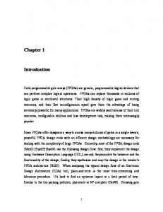
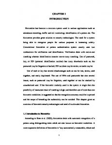
withstand the operating pressure in this second case the water pressure is converted into kinetic energy before entering the runner. The kinetic energy is in the form of a high speed jet that strikes the buckets, mounted on the periphery of the runner. Turbines that operate in this way are called impulse turbines. As the water after striking the buckets falls into the tail water with little remaining energy the casing can be light and serves the purpose of preventing splashing [1]. Mechanical energy is that which is associated with moving or rotating parts of machines, usually transmitting power. Machine used hydraulic energy. So that the output is in the form of a rotating shaft or a moving part of a machine part of machine, is known as turbine. To get started we’ll need a few essential facts. Most important are accurate HEAD and FLOW measurements. The potential energy in the water is converted into mechanical energy in the turbine by one of two fundamental and basically different mechanisms. The water pressure can apply a force on the face of the runner blades which decreases as it proceeds through the turbine. In the fig (1.1) explained the reaction water turbine [1].
Fig. (1.1) Reaction water turbine.
3
Chapter 1 Introduction & Theory of turbines
1.3 Theory of turbine
•
Impulse turbines:
These turbines change the direction of flow of a high velocity fluid jet. The resulting impulse spins the turbine and leaves the fluid flow with diminished kinetic energy .there is no pressure change of the fluid in the turbine rotor blades. Before reaching the turbine the fluid’s pressure head is changed to velocity head by acceleration the fluid with a nozzle. Pelton wheels and de Laval turbines use this process exclusively. Impulse turbines do not require a pressure casement around the runner since the fluid jet is prepared by a nozzle prior to reaching turbine. Newton’s second law describes the transfer of energy for impulse turbines.
•
Reaction turbines:
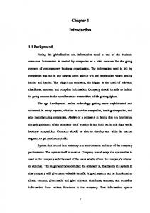
These turbines develop torque by reacting to the fluid’s pressure or weight. The pressure of the fluid changes as it passes through the turbine rotor blades. A pressure casement is needed to contain the working fluid as it acts on the turbine stage (s) or the turbine must be fully immersed in the fluid flow (wind turbine). The casing contains and directs the working fluid and, for water turbines, maintains the suction imparted by the draft tube. Francis turbines and most steam turbines use this concept. For compressible working fluid multiple turbine stages may be used to harness the expanding gas efficiently. Newton’s third law describes the transfer of energy for reaction turbines [2]. In the Fig (1.2) explained of turbine application chart between head (M) with flow rate (M3/s). Typical range of heads:
• • • •
Kaplan
2 < H < 40 (H = head in M)
Francis
10 < H < 350
Pelton
50 < H < 1300
Turgo
50 < H < 250
4
Chapter 1 Introduction & Theory of turbines
Fig (1.2) The heads of different turbines.
1.4 Different types of Francis turbine There are two main types of Francis turbines, namely(i) (ii)
Closed type and Open flume type.
Closed Type Francis Turbine: In this type the water is led to the turbine through the penstock whose end is connected to the spiral casing of the turbine. The closed type Francis turbine may be of two types, horizontal and vertical. The horizontal type is used for medium and high head and the vertical type for medium or low head. Open flume Type Francis Turbine: In the open flume Francis turbine a concrete chamber replaces the spiral casing. This type turbine is used for 5 to 10 m heads [14].
5
Chapter 1 Introduction & Theory of turbines
1.5 Major components of Modern Francis Turbine 1.
Runner: The flow in the runner of a modern Francis turbine is not purely radial but a combination of radial and axial. The flow is inward, that is, from the periphery towards the centre. The width of the runner depends upon the specific speed. The high specific speed runner is wider than the one which has a low specific speed because the former has to work with a large amount of water.
2.
Shaft: The runner is keyed to the shaft which may be vertical or horizontal. The turbine is accordingly specified as vertical or horizontal type. The shaft is generally made of steel and is forged. It is provided with a collar for transmitting the axial thrust to the bearing.
3.
Bearing: The turbine is generally with one bearing. In vertical type the bearing carries full runner load acts as trust-cum-supporting bearing. Right selection of bearing is, therefore extremely important. The lubrication of the thrust bearing also plays an important part in the running of the turbine.
4.
Spiral casing or Scroll casing: To avoid loss of efficiency, the flow of water from the penstock to the runner should be such that it will not from eddies. In order to distribute the water around the guide ring evenly, the scroll casing is designed with a cross=sectional area reducing uniformly around the circumference, maximum at the entrance and nearly zero at the tip. This gives a spiral shape and hence the casing is named as spiral casing.
5.
Guide vane or (wicket gate): The guide vanes or wicket gates, as they are sometime called are fixed between two rings in the form of a wheel in the form of a wheel known as guide wheel. The guide vanes have a cross-section known as aerofoil section. This particular cross-section allows water to pass over them without forming eddies and with minimum friction losses. Each guide vane can rotate about its pivot center which is connected to the regulating ring by means of link and a lever. The ring is connected to the regulating shaft by means of regulating rods generally two in runner. The guide vanes can be closed or opened thus allowing a variable quantity of the water according to the needs.
6
Chapter 1 Introduction & Theory of turbines
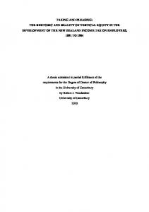
Fig.(1.3) Outlines of Francis turbine 6.
Draft tube: The water after doing work in the runner passes on to the tail race through a draft tube which is a welded steel plate pipe or a concrete tunnel, its cross-section gradually increasing towards the outlet. The draft tube is a conduit which connects the runner exit to the tail race. The tube should be drowned approximately one meter below the lowest tail race level. The functions of the draft tube are as follows: 7
Chapter 1 Introduction & Theory of turbines
(i)
(ii)
7.
If the water is discharged freely from the runner turbine will work under a head equal to the height of the head race water level about runner outlet. The water leaving the runner still possesses a high velocity and this kinetic energy would be lost if it is discharged freely as in Pelton turbine. By employing a draft tube of increasing cross section the enclosed conduit is extended up to the out let end of the tube and discharge take place at a much reduced velocity thus resulting in a gain of pressure head.
Guide blade or (guide wheel): The guide blade governing the vanes. the guide vanes or wicket gates, as they are sometime called are fixed between two rings in the form of a wheel in the form of a wheel known as guide wheel[14].
1.6 Material Selection Material used for manufacture of different components are in table (1.1)[14]. COMPONENT
MATERIAL
shaft
Steel and is forged
Runner
Cast in one piece or may be made of separate steel plates welded together. Cast iron for small output, cast steel for large output and stainless steel or a non-ferrous metal like bronze when the water is chemically
Draft tube
a draft tube which is a welded steel plate pipe or a concrete tunnel.
Guide vanes
Cast steel.
Spiral casing
Depends upon the heads which are as follows. Concrete without steel plate – up to about 30m Welded rolled steel plate-
up to 100m
Cast steel-
up to than 100m
Guide blade
Cast steel
penstock
Quarters and welded at the site inspected by X-rays Table (1.1) Materials used for different components.
8
Chapter 1 Introduction & Theory of turbines
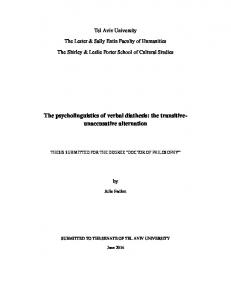
1.7 Problem of Cavitation Many high Reynolds number flow of practical importance contain a region of concentrated vorticity where the pressure in the vortex core is often significantly smaller than the rest of the flow. Such is the case, for example, in the tip vortices of ship’s propeller or pump impellers or in the swirling flow in the draft tube of a water turbine. it follows that cavitations inception often occurs in the vortices and that with further reduction of the cavitations number, the entire core of the vortex may become filled with vapor. Naturally the term “vortex cavitations” is used for these circumstances. In fig (1.4) we present some example of this particular kind of large scale cavitations structure. Consists of photographs of cavitations tip finite aspect ratio hydrofoil at an angle of attack. Cavitations inception occurred in the vortex some distance downstream of the tip at a cavitations number of about σ=1.4. with further decrease in pressure the cavitations in the core becomes continuous, as illustrated by the picture on the left in fig (1.4) this transition is probably triggered by an accumulation of individual bubbles in the core they will tend to migrate to the center of the vortex due to the centrifugal pressure gradient. With further decrease in σ, bubble and /or sheet cavitations appear on the hydrofoil surface fig (1.4) disturb the tip vortex which is nevertheless still apparent [3].
Fig (1.4) cavitations.
1.8 Specific speed We have seen that specific speed is a measure of the speed a turbine under certain conditions (H, Q) and determines the design of the turbines and consequently its shape (above all the shape of the runner). In this way turbines are classified into certain types according to the following table:[4] 9
Chapter 1 Introduction & Theory of turbines
Ns
Turbine type
4 to 35
Pelton wheel with 1 nozzle
17 to 50
Pelton wheel with 2 nozzles
24 to 70
Pelton wheel with 4 nozzles
80 to 120
Francis turbine low speed
120 to 220
Francis turbine normal
220 to350
Francis turbine high speed
350 to430
Francis turbine express
300 to1000
Propeller and Kaplan turbine
Table (1.2) type of specific speed in turbines.
1.9 Classification of Hydraulic turbines The hydraulic turbines are classified according to the type of energy available at the inlet of the turbine, direction of flow through the vanes, head at the inlet of the turbine and specific speed of the turbines. Thus the followings are the important classification of the turbines: 1. According to the type of energy at inlet: (a) Impulse turbines (b) Reaction turbine. 2. According to the direction of flow through runner: (a) Tangential flow turbine
(b) Radial flow turbine,
(c) Axial flow turbine, and
(d) Mixed flow turbine.
3. According to the head at the inlet of turbine: (a) High head turbine
(b) Medium head turbine, and
(c) Low head turbine. 4. According to the specific speed of the turbine: (a) Low specific speed turbine, (b) Medium specific speed turbine and (c) High specific speed turbine[5].
1.10 Definition of Various Terms 1)
Specific speed: It is the speed of an imaginary turbine identical with the given turbine which would produce unit power while working under head of 1 m. 10
Chapter 1 Introduction & Theory of turbines
2)
𝑁 √𝑃
Ns = 5/4 𝐻 Head (H): It is the discharge used by a turbine while working under a head of 1m. Let H = actual head in metre under which a turbine is working.
3)
4)
4)
5) 7)
Discharge (Q): Actual discharge through the turbine in m³/s under the actual head of H meter. Power (P): Actual power developed by the turbine in kw under the actual condition. (Pu) It is the power developed by a turbine while working under a head of 1 meter. Power developed by the same turbine if it works under a head of 1metre = unit power. Unit speed (Nu): Speed of a turbine while working under a head of 1m, is called unit speed. Nu = r.p.m. of the runner when head 1m. Unit discharge (Qu): 𝑄 Unit discharge is given by Qu = . Q = discharge of the turbine in m³/s. √𝐻
Gross head. The difference between the head race level and tail race level when no water is flowing is known as Gross head. It is denoted by Hg.
11