Available online at www.sciencedirect.com
ScienceDirect Physics Procedia 56 (2014) 72 – 81
8th International Conference on Photonic Technologies LANE 2014
Characterization of effect of support structures in laser additive manufacturing of stainless steel Jukka-Pekka Järvinena, Ville Matilainena, Xiaoyun Lia, Heidi Piilia, Antti Salminena,b,*, Ismo Mäkeläc, Olli Nyrhiläd a
Lappeenranta University of Technology, Lappeenranta 53850, Finland b Machine Technology Centre Turku Ltd, Turku, Finland c DeskArtes Oy, Espoo, Finland d EOS Finland Oy, Turku, Finland
Abstract Laser additive manufacturing (LAM) of stainless steel is a layer wise technology for fabricating 3D parts from metal powder via selectively melting powder with laser beam. Support structures play a significant role in LAM process as they help to remove heat away from the process and on the other hand hold the work piece in its place. A successful design of support structures can help to achieve a building process fast and inexpensive with high quality. Aim of this study was to characterize the usability of two types of support structures: web and tube supports. Purpose of this study was also to analyze how suitable they are in two industrial application cases: case for dental application and case for jewelry application. It was concluded that the removability of web supports was much better than tube supports. It was noticed that support structures are an important part of LAM process and they strongly affect the manufacturability and the end quality of the part. © 2014 The Authors. Published by Elsevier B.V. This is an open access article under the CC BY-NC-ND license © 2014 The Authors. Published by Elsevier B.V. (http://creativecommons.org/licenses/by-nc-nd/3.0/). Selection and blind-review under responsibility of the Bayerisches Laserzentrum GmbH. Peer-review under responsibility of the Bayerisches Laserzentrum GmbH Keywords: Additive manufacturing; laser; support structure; web support; tube support; stainless steel
*Corresponding author. Tel.: +358-407674387 . E-mail address:
[email protected]
1875-3892 © 2014 The Authors. Published by Elsevier B.V. This is an open access article under the CC BY-NC-ND license (http://creativecommons.org/licenses/by-nc-nd/3.0/). Peer-review under responsibility of the Bayerisches Laserzentrum GmbH doi:10.1016/j.phpro.2014.08.099
Jukka-Pekka Järvinen et al. / Physics Procedia 56 (2014) 72 – 81
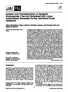
1. Introduction Laser additive manufacturing is a layer wise technology for fabricating physical objects with a laser beam. As laser additive manufacturing is faster and more accurate compared to the conventional technologies, it has started to gain a position to be used wider and wider as an alternative fabrication technology in the manufacturing industry. Support structures are extremely important part of whole technology, especially when building metallic parts as they are crucial part of success of this fabrication technology. Aim of support structures in laser additive manufacturing of metallic materials is firstly to conduct the heat away and secondly to hold the work piece in its place, Sometimes a small change on the part orientation or the shape of the part enables reduced volume of the support structures. Many different types of supports are used in the industry such as block, point or line supports (see Fig. 1). Each of these supports has its own features and suitable uses. The objective of this study was to examine and compare the properties of two types of support structures (web supports and tube supports).
Fig. 1. Different support geometries for metallic parts. (Krol et al., 2012).
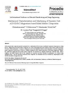
2. LAM support structures Support structures are required in most laser additive manufacturing (LAM) processes firstly to conduct the heat away, and secondly for holding the fabricated work piece in building platform during manufacturing process. Purpose of support structures is also to sustain the overhang surfaces and to avoid distortion caused by internal stresses. An overhang structure does not have any built metallic structures underneath it, only the powder bed. As laser additive manufacturing is a layer wise process the form of the first layer is important for the subsequent layers so making it stable without deformations is necessary. Overhang features have no underlying solid layer to support them at any point. Therefore they are more prone to deformations during manufacturing caused by gravity, internal heat and residual stresses (Hussein et al., 2013; IC professional Training Series, 2009). Fig. 2 presents the problem occurring in an overhang part without support structures (Kozo et al., 2006).
Fig. 2. Fracture of overhanging part of model during forming in SLM (Kozo et al., 2006).
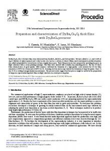
Although the support structures are mandatory in LAM they are often massive and require additional work to remove. The support structures designed by the need can reduce manufacturing and finishing work and costs. Experiments by Cloots illustrated that overhang parts with the angle less than 35° in the horizontal direction need support structures. Cloots et al. (2013), Thomas (2009). Thomas (2009) concludes that support structures can also act as a heat removal element in the process to avoid or reduce the effect of the residual stresses. The residual stresses are formed as a result of the thermal cycle for example heating, solidification and cooling. Fig. 3 shows a part with a crack caused by residual stresses.
73
74
Jukka-Pekka Järvinen et al. / Physics Procedia 56 (2014) 72 – 81
Fig. 3. Cracks caused by thermal stresses. (Kruth et al., 2012).
In LAM process, the powder material is melted and solidified under high laser energy and the parts are built layer by layer. Therefore the heat is conducted layer by layer in the part during the process. Support structures are contacted with the built part and they act as a heat conductor to transfer the heat away from the work piece. Because of the heat dissipation the impacts from the residual stresses on the process are quite stable so the problems which are caused by thermal stresses will not occur. Conversely poor design of support structures can make their own displacement and interrupt the build process (Gibson et al., 2009). Powder material is processed in LAM under a high temperature, usually over the melting point, so the residual stresses still remain after cooling and the thermal stresses inside the component become higher. This is why rapid cooling may also cause other defects (such as cracks, shrinkage, and curling etc.) in some parts of the work piece. The contraction of material occurs when cooling makes the non-supporting material distort away from the powder material surface. These distortions include cracks, curling up, sag and shrinkage. Support structures can solute these problems as well (Thomas, 2009). Support structures are not the real functional part of the built component and typically all the support structures should be removed after the building process. For example, a support structure with a large contact area to the main part is difficult to remove and it might damage the part surface after removal and leave bad surface quality to the components. Accurate selection of support structures are important to the whole process and it affects production time, cost, and even the success or failure of the component. Optimizing the support structures is important for successful manufacturing process (Thomas, 2009; Pullin and Offen, 2008). Support structures have many design rules which all need to be outlined. The designer should consider the production time, the amount of material and how to build and remove the support structures. In order to avoid surface damage supports should be designed under certain restriction. For example the supports should have minimized contact area with the parts. Sometimes support structures could be created automatically by some commercial software but they are not always able to adapt to the complex geometries and typically overestimate in terms of thickness (Jhabvala et al., 2011). Different components need the relevant amount of supports. Usually the amount and geometries of support structures depend on the main part parameters, shapes and orientation choice (Gibson et al., 2009). Part orientation largely affects the support structures selection. For instance, optimized part orientation can reduce the number of the required supports. The designers need to consider the optimal orientation which can be used according to manufacturing requirements (Thomas, 2009). 3. Experimental procedure 3.1. LAM machine used in this study The laser source used in the experiments was IPG YLS 200W SM CW ytterbium fiber laser with a wavelength of 1070 nm. The laser beam is continuous wave (CW). The output of the IPG YLS 200W SM CW laser machine is 200 W and it operates in single mode. The laser beam is transported from the laser to the scanner optics via optical fiber. The laser beam is transferred to LAM chamber with Scanlab hurrySCAN 20 scanner. In this study, a focal point size of 100 ȝm was used. The laser additive manufacturing machine in the experiments was a modified
75
Jukka-Pekka Järvinen et al. / Physics Procedia 56 (2014) 72 – 81
research machine that represents EOSINT M-series and it is located at Laboratory of Laser Materials Processing of Lappeenranta University of Technology. Equipment consists of laser source, scanner, control movement software and LAM chamber. Nitrogen was used as shielding gas in this study and the 3D file manipulation and slicing was made with Netfabb software. Fig. 4 shows the modified LAM machine used in the study experiments. The building platform was milled before using. The oxygen level in the laser additive manufacturing chamber is 0.3 % and the operating temperature is 80 °C. Scanlab hurrySCAN 20
LAM platform
Fig. 4. LAM machine used in this study with IPG YLS 200W SM CW .
The main parameters of LAM machine used in the study are shown in Table 1. Table 1. Technical data of modified research LAM equipment representing EOSINT M-series used in this study. Parameters
Characteristics
Building volume
250 x 250 x 215 mm
Building speed
2-20 mm3/s
Layer thickness
20-100 ȝm
Scan speed
Up to 7.0 m/s
Variable focus diameter
100-500 ȝm
Nitrogen generation
Standard
Compressed air supply
7000 hPa; 20 m3/h
Building volume
250 x 250 x 215 mm3
3.2. Materials used in this study Stainless steel powders are widely used in the additive manufacturing industry because of their good mechanical properties. EOS 17-4 PH was used as test material in this study. 17-4 PH is a martensitic precipitation-hardening stainless steel that features a combination of high strength, good corrosion resistance and good mechanical properties. Table 2 gives the composition of EOS 17-4 PH of UNS S17400 (DIN 1.4542). Table 2. Compositions (wt %) of EOS 17-4 PH stainless steel. Component
Fe
Ni
Mo
Cu
Cr
Mn
Si
C
P
S
O
N
Nb
Concentration (Wt %)
73.8
4.2
0.4
3.9
15.8
0.7
0.7
0.1
0.1
0.1
0.1
0.1
0.3
The powder of 17-4 PH can be fully melted with 20 ȝm layer thickness. It is also possible to use skin and core building style to increase the build speed and reduce the residual stress. Skin and core strategy in additive manufacturing means that the outer region and the inner part are built by one time but with different energy concentration or different density. EOS 17-4 PH is widely used in variety of medical, aerospace and other
76
Jukka-Pekka Järvinen et al. / Physics Procedia 56 (2014) 72 – 81
engineering applications requiring high hardness, strength and corrosion resistance. The typical applications include for example functional prototypes, small series products, individualized products or spare parts. 3.3. Test pieces in this study Test piece used in this study is represented in Fig. 5. The base part is a trapezoidal. Dimensions of three sides (sides A, B, C) are 60.00 mm, one (side D) is 63.30 mm and the height of the base part is 26.40 mm. The blue letters in Fig. 5 means the left side and the right side when the surface qualities were evaluated. The left and right mean the left and the right when the observer is facing to each side. As it is shown in Fig. 5 there are 31 bars with different angles on the top-facing surface of the test piece. The length of the bars is 20 mm. The bars of the test piece are numbered with angles in Table 3.
Fig. 5. Test piece used in this study. Blue letters indicate left and right side when the surface qualities were evaluated.
Table 3. Angles of the bars of the test piece (N/A=no measurement data available). Bar no.
Direction parallel to recoater direction
Direction perpendicular to reacoater direction
Tilting angle of bar, degree
Tilting angle of bar, degree
A
B
C
D
1
65
65
65
65
2
60
60
60
60
3
55
55
55
55
4
50
50
50
50
5
N/A
45
45
45
6
N/A
40
40
40
7
N/A
35
35
35
8
N/A
30
30
30
9
N/A
25
25
25
The support structures were designed to support these bars. The test piece is orientated as shown in Fig. 6, and the recoater movement is indicated with an arrow in the figure.
Fig. 6. Orientation of the test piece and the recoater movement direction.
Jukka-Pekka Järvinen et al. / Physics Procedia 56 (2014) 72 – 81
Two different support structures were generated in the experiments for the test piece: web supports and tube supports. Support structures were designed with 3Data Expert software created by the company DeskArtes (Finland). The support structures were crated to be easily removed without damaging the test part surface so the supports needed to be as low volume as possible. The web supports (see Fig. 7) are designed to support overhanging down-facing surfaces of bars of the test piece. The webs of the supports are used to reduce the contact area of the part surface and let the unexposed powder to be easily removed. Dimensions of web supports are 1.30 mm (sample 1) and 1.45 mm (sample 2).
Fig. 7. Web supports generated with 3Data Expert.
The design principle of tube supports (see Fig. 8) was to lower the support volume. As the tubes are hollow the contact surface is smaller which reduces the surface damage after the removal of the supports. The diameters of the tube supports are 1.30 mm and 2.00 mm and they were ranged as sample 3 and 4.
Fig. 8. Tube supports generated with 3Data Expert.
4. Results and discussion There were several pieces of web support structures lost or nearly lost before the removal of the part by sawing. The rest of the supports were planned to be removed manually by some simple tools. The supports of side A and the inner supports (bars with 65, 60, 55, 50 degrees) of B, C and D side could not be removed with pliers because all of these supports were based on the main part’s surfaces (see Fig. 5). Therefore only the supports of 25 to 45 degrees could be removed. Table 4 gives the evaluation of the removability of web supports of each bar. As it can be noticed from Table 4, the web supports were quite easily removed. Most supports were very loose and could be removed without tools or removed easily with pliers. Table 4 also shows that generally the smaller the angle is the easier it is to remove the support structure. It can be also said that the diameter of the support affects its removability. A support with a larger diameter is easier to remove than a support with a small diameter. Fig. 9 shows macrographs of web support structures with dimension of 1.3 mm and Fig. 10 represents macrograph of web support structures with dimension of 1.45 mm.
77
78
Jukka-Pekka Järvinen et al. / Physics Procedia 56 (2014) 72 – 81 Table 4. Removability evaluation of web supports. (5 = very easy to remove, 4 = easy to remove, 3 = average, 2 = hard to remove, 1 = very hard to remove, 0 = extremely hard to remove). Sample and side
1 (1.3 mm)
2 (1.45 mm)
Angle, degree 25
30
35
40
45
B
5
5
4
4
4
C
5
5
4
4
4
D
5
4
4
4
4
B
3
5
5
4
4
C
3
5
5
5
5
D
3
5
4
4
4
Fig. 9. Macrographs of web support structure with dimension of 1.3 mm.
Fig. 10. Macrographs of web support structure with dimension of 1.45 mm.
As it can be seen from Fig. 9 and Fig. 10, some of the support structures were already detached during the cutting of the pieces which indicates that the supports would be easy to remove. When the digital model is compared to the manufactured piece, it can be seen that there are nearly no deformations and also the teeth between the support and the part are manufactured well (see Fig. 11).
Fig. 11. The teeth of the digital model compared to the micrographs of web support test pieces.
79
Jukka-Pekka Järvinen et al. / Physics Procedia 56 (2014) 72 – 81
Most of the support structures in samples 3 and 4 were tightly attached to the main part after cutting. Sample 3 had no missing supports and sample 4 only lost six small pieces of tubes. The supports were first removed manually with pliers. Table 5 gives the evaluation the removability of tube supports of each bar (as mentioned before the bars are from the outer of B, C and D side). Table 5. Removability evaluation of tube supports. (5 = very easy to remove, 4 = easy to remove, 3 = average, 2 = hard to remove, 1 = very hard to remove, 0 = extremely hard to remove). Sample and side
3 (1.3 mm) 4 (2.0 mm)
Angle, degree 25
30
35
40
45
B
0
0
0
0
0
C
0
0
0
0
0
D
0
0
0
0
0
B
2
2
2
2
2
C
2
2
2
2
2
D
2
2
2
2
2
As it can be observed from Table 5, the removability of tube supports of each sample was the same. The supports of sample 3 could not be removed at all but the supports of sample 4 could be removed with higher force than the web supports. When supports of sample 3 and sample 4 were compared to each other, sample 3 had smaller supports but a larger number than sample 4. These smaller supports were more stable because they had larger contact area than the larger supports in sample 4. Fig. 12 illustrates macrographs of tube supports structures with diameter of 1.3 mm and Fig. 13 shows macrograph of tube support structure with diameter of 2 mm.
Fig. 12. Macrographs of tube support structure with diameter of 1.3 mm.
Fig. 13. Macrographs of tube support structure with diameter of 2 mm.
According to Fig. 12 and Fig. 13, the reason for poor removability of supports in sample 3 might be that the tubes and the bar surfaces are melted together. Therefore the contact area between the support and the main part is too large making the supports very hard to remove. This issue needs further studies with different tip sizes and shapes. The tip of the tube supports should have been sharper in order to increase the removability. The digital models compared with the physical test pieces are shown in Fig. 14.
80
Jukka-Pekka Järvinen et al. / Physics Procedia 56 (2014) 72 – 81
Fig. 14. Digital model (figure a and c) compared with the tube supports micrographs (figure b and d) of test pieces.
Fig. 14 shows that the supports of sample 3 (see Fig. 14b) were not fabricated as well as the original design of the digital models. There should have been a small gap between each tube however some of the tubes were jammed together and melted with the bars (see the red circle in Fig. 14b). The supports of sample 4 were much better: there are visible gaps (see the yellow circle in Fig. 14d) between each tube and the tubes connected to the bars with the top points which were the same as the digital model design. As it can be seen from sample 3, it might be the same problem as the first design that the dimension was not large enough (the dimension of sample 3 is 1.30 mm) and the supports melted together during the process. As concluded, this issue needs further studies. This problem might cause more work when supports are removed. Table 6 shows comparison of overall properties of web and tube supports. Table 6. Comparison of overall properties of web support and tube support. (5 = excellent, 4 = good, 3 = average, 2 = bad, 1 = very bad, 0 = extremely bad). Web support Tube support 1.30 mm
1.45 mm
1.30 mm
2.00 mm
Removability
4
4
0
2
Surface quality - top
5
5
0
5
Surface quality - bottom
1
1
0
0
Surface quality - right
4
4
0
4
Surface quality - left
4
3
0
4
As it can be noticed from Table 6, the removability of web supports is overall much better than that of the tube supports. However, even within these two support types there can be many different kinds of geometries and sizes for example regarding the contact point between the support and the main part so these results do not necessarily apply to all web and tube supports in general. The top surfaces in both cases have good quality. Bottom surfaces are all very poor although web supports are slightly better. The right and left surfaces of the bars are good. 5. Conclusions and further studies Objective of this study was to examine and compare the properties of two types support structures (web supports and tube supports). Each type of support was manufactured as two different sizes: the square sizes of web supports were designed as 1.30 mm and 1.45 mm and the tube diameters were designed as 1.30 mm and 2.00 mm. The support structures were designed with 3Data Expert which is a professional commercial software of DeskArtes Oy (Finland). The study was executed in Laboratory of Laser Processing at Lappeenranta University of Technology (Finland). Test material was EOS 17-4 PH stainless steel. Laser equipment used in the experiment was IPG YLS
Jukka-Pekka Järvinen et al. / Physics Procedia 56 (2014) 72 – 81
200W SM CW Ytterbium fiber laser with a wavelength of 1070 nm and the laser additive machine that was used was a prototype machine equivalent to EOSINT M-series machines. The main topics of this study were the removability of the support structures and the surface quality of the parts. The removal work was done without a machine as the removability should be judged if the supports were easy to be removed or not. The surface qualities were studied on the four sides of the bars where the supports could be removed (B, C and D side bars with angles from 25° to 45°). The removability was evaluated as six levels from 0 to 5 of each study bar. 5 represented easy removal and 0 very hard to be removed. Web supports and tube supports were at first studied separately and then the results of each side were compared together. The removability of the web supports was much better than that of the tube supports. Most of the web supports could be removed easily by hand however some small pieces of supports were difficult to remove as the supports were connected with the test piece or with other supports. Tube supports were quite hard to remove and smaller size tube supports could not be removed by hand at all. It was concluded that further study is needed when optimizing the contact areas between supports and the main part. Also the dimensions of the support structures should be studied more. It was noticed in this study that a small change of the part orientation or the shapes of the parts enable the reduced volume of support structures. Many different types of supports are used in the industry such as wall-like supports, tree-like supports and cellular supports. Support structures are used in laser additive manufacturing to support the part that is being built and to avoid collapsing and deformation (by powder material deposition by recoater). On the other hand support structures work as a heat conductor removing the heat used in the process which makes the internal thermal conditions stable during building and they help to avoid the part being peeled away or cracking by the residual thermal stresses. Although support structures are useful in manufacturing they must be removed afterwards. This means waste of material, time and cost. Acknowledgements This work was done as a part of project called FAST COINS which is a project for Fast Co-Tuning for Individual Needs. This project is funded by TEKES - The Finnish Funding Agency for Technology and Innovation with involvement of Lappeenranta University of Technology (LUT), Saimaa University of Applied Sciences (Saimia) and Finnish industrial partners. Main goal in the project is to examine fast development methods which create flexible roadmaps for innovations to become successful business stories. Authors thank all participants of the project for their knowledge and input to this article. Authors express as well their gratitude to EOS Finland and DeskArtes Oy for their feedback and support to be able to execute and publish this study. Authors thank also all the personnel of LUT Laser for their knowledge given to this article. References Cloots, M., Spierings, B,A., Wegener, K., 2013. Assessing new support minimizing strategies for the additive manufacturing technology SLM. International Solid Freeform Fabrication Symposium An Additive Manufacturing Conference, Austin, August 12-14, 2013. The University of Texas. Gibson, I., Rosen, W, D., Stucker, B. 2009. Additive Manufacturing Technologies. London: Springer New York Heidelberg Dordrecht. ISBN: 978-1-4419-1119-3 Hussein, A., Yan, C., Everson, R., Hao, L, Yong, P. 2013. Advanced Lattice Support Structures for Metal Additive Manufacturing. Materials Processing Technology 213 (2013) 1019-1026 Jhabvala, J., Boillat, E., André, C., Glardon, R., 2011. An Innovative Method to Build Support Structures with a Pulsed Laser in the Selective Laser Melting Process. London. Springer. P137-142 Kozo, O., Masanori, S. (2006). Flexible manufacturing of metallic products by selective laser melting of powder. International Journal of Machine Tools and Manufacture. Volume 46, Issue 11. September 2006. P1188-1193, ISSN 0890-6955 Pullin, J., & Offen, A. (2008). ‘Back to the Drawing Board - Addressing the design issues of RM’. Time Compression Technologies Rapid Manufacturing Conference 2008, Rapid News Publications Plc, Coventry, West Midlands, October 2008, [CD-ROM] Rapid Prototyping & Manufacturing Technologies 2009. IC Professional Training Series, Industrial Centre, Hong Kong Polytechnic University Thomas, D., 2009, The Development of Design Rules for Selective Laser Melting. Ph.D. Thesis, University of Wales, Cardiff
81