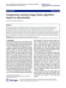
Zachary Wartell, Larry F. Hodges, William Ribarsky. Georgia Institute of ...... [22] David A. Southard, âTransformations for Stereoscopic. Visual Simulation ...
Characterizing Image Fusion Techniques in Stereoscopic HTDs Zachary Wartell, Larry F. Hodges, William Ribarsky Georgia Institute of Technology
Abstract Stereoscopic display is fundamental to many virtual reality systems. Stereoscopic systems render two perspective views of a scene one for each eye of the user. Ideally the user’s visual system combines the stereo image pairs into a single, 3D perceived image. In practice, however, users can have difficulty fusing the stereo image pair into a single 3D image. Researchers have used a number of software methods to reduce fusion problems. We are particularly concerned with the effects of these techniques on stereoscopic HTDs (Head-Tracked Display). In these systems the head is tracked but the display is stationary, attached to a desk, tabletop or wall. This paper comprehensively surveys software fusion techniques. We then geometrically characterize and classify the various techniques and illustrate how they relate to stereoscopic HTD application characteristics. Keywords: stereoscopic distortion, stereoscopic HTD
1 Introduction Virtual environments aim to perceptually place the user in a computer generated world. A key component of creating this illusion is interactive 3D imagery. To generate this imagery, a typical VR system has a location and orientation tracking device, an image generator and one or more displays. The tracking device determines the positions of the user’s head and/or eyes and of the displays. The image generator computes the image that each eye would see on a display surface if the eye and the display existed inside the virtual world at their tracked positions. This image is then fed to the display. A VR system is typically configured either as a head-mounted display (HMD) or as a head-tracked display (HTD). In a HMD, the display is attached to a helmet or headset worn by the user, so both the eye points and the display move with the user. In a HTD, the display is stationary, attached to a desk, tabletop, or wall. Hence only the eye points move. HTD examples are the CAVE [2], fish tank VR [28], and
the virtual workbench [10]. This paper focuses on stereoscopic HTDs. Many VR systems generate a pair of images, one for each eye. This stereoscopic imagery provides a true 3D image so virtual objects appear to exist in front of and behind the physical display surface. Software methods for stereoscopic display are well known [8] [19][23]. Stereoscopic display for virtual reality has been shown to improve user depth perception and task performance in a variety of tasks [5][20][28]. This is not surprising since real world experience shows that stereopsis is an important depth cue especially for objects within the user’s personal space (1.5 m) [4]. Stereoscopic displays add additional challenges to interface design. Both experience [11] and experimental studies [25][37] show that users with normal stereoscopic vision often have trouble fusing stereo image pairs into a single 3D image when the viewing geometry is modeled exactly. Users may experience headaches, eye strain and/or fatigue. At extremes they may be unable to fuse the image pair into a single 3D image. Researchers use a variety of techniques to keep virtual geometry easily fusible. This paper provides a comprehensive survey of software fusion techniques that geometrically manipulate the scene. Often these manipulations geometrically compress the stereoscopic depth range of a scene. There is a conflict between providing the geometrically accurate range of stereoscopic depth and reducing it to lessen fusion problems. The stereoscopic display literature is filled with various recommended fusible depth range limits. Section 2 covers these in detail. Applying these inevitably entails distorting the presented stereo geometry. Such distortions may interfere with direct manipulation tasks in VR. Certain VR applications such as medical training would probably choose an accurate representation over viewing comfort in order to minimize distortion. Determining the best balance between display accuracy and fusion comfort is a difficult problem. This paper surveys the various geometric techniques developed in the stereoscopic display literature and examines the theoretic implications of each technique’s distortion. We focus
on implications for stereoscopic HTD’s. While HMD’s are equally important, the geometry of HMD’s requires further geometric analysis which is beyond the scope of this paper. We then characterize and classify the various techniques and illustrate how they relate to stereoscopic HTD application characteristics. The paper also presents some new observations and summarizes recent work. While we do not perform human factors studies, we combine data from the stereoscopic display literature with theoretic geometric analysis of various fusion control techniques. This is an important step to inform further experimental investigation. Readers will gain a better understanding of how image fusion issues interact with other stereo HTD application considerations and what trade-offs are involved. 2 Background Projection Plane L Eyes
hva
α
pβ
Virtual Point
R
Figure 1: Illustration of screen parallax (p), and HVA (hva); vergence difference,α-β. Fusion problems occur for several reasons [5]. When fixating on a target object in the real-world, a human’s eyes perform two actions. Each eye rotates so as to bring the target into the center of each eye’s field of view. This is called vergence. Also each eye adjusts, or accommodates, the shape of its lens to bring the target into focus. In the real world, these two activities are synchronized. When fixating on a virtual object in a stereoscopic display, however, the eyes converge on the virtual target but accommodate elsewhere, nominally to the depth of the physical display. This violates the natural relation between accommodation and vergence. Additionally, in a physical environment often only a small range of depth about the fixation point typically remains in focus while objects outside this depth of field are blurred. In contrast, in common implementations of stereoscopic, virtual environments all objects remain in focus regardless of depth. Evidence suggests that a larger range of stereoscopic disparity can be fused when images are blurry instead of sharp. Hence, in a virtual environment the lack of image blur can reduce the fusible depth range around the fixation point. While simulating depth of field can extend this range [16] and anecdotally reduces discomfort [14], dynamic
simulation of depth of field as the user fixates on different depths requires multi-pass rendering which significantly reduces framerate on current hardware. Finally, many stereoscopic HTDs suffer from crosstalk. This occurs when the optical system allows the displays left eye channel to pass a faded image of the right eye image and visa-versa. If the cross-talk and image disparity grow too large, viewers cannot fuse the images and perceive ghost images of the right eye image with their left eye and visa-versa. Fusion limits vary with a variety of factors related to the physical display technology and individual differences and the amount of user experience with stereoscopic displays [25][37]. There are a variety of metrics used to characterize these limits. Screen parallax is the signed distance measured on the screen between two corresponding image points (p in Figure 1) [9]. The horizontal visual angle (hva in Figure 1) is the angle subtended by the screen parallax [37]. A third metric is vergence angle difference. The vergence angle for a point in space is the angle between the optic axes of the two eyes when the eyes fixate on that point. The vergence difference for point P is P’s vergence angle minus the display’s vergence angle [22][27]. In Figure 1, the vergence difference for P is α-β. For all three metrics 3D points behind the screen have positive values while 3D points in front of the screen have negative values. A given metric and recommended limit value pair implies a limited range of depth that should be displayed in front and behind the screen. Generally, the range of allowable parallax grows with observer distance from the screen [12]. Valyus [27] gives a vergence difference range of +/- 1.6 degrees. Yeh and Silverstein [37] experimentally find a fusible HVA range of -4.93 to 1.57 degrees for viewing durations that allow ocular vergence (2 s) and a HVA range of -27 min arc to 24 min arc for viewing durations that don’t allow ocular vergence (200ms). They recommend keeping applications to the smaller of these ranges. William’s and Parrish’s experiments suggest a viewing volume of –25% through +60% of the screen distance. These data use the criteria of comfortable, fused vision in front of the screen and less than 10% perceived depth error behind the screen. Subjects viewed a virtual rod while adjusting the depth of a physical marker to match the virtual rod’s depth. Seigel and Nagata [21] empirically investigate using the minimum possible stereo parallax that still yields a sense of stereoscopic depth. Subjects view stereoscopic video of a scene appearing behind the screen. Even when the maximum screen parallax is reduced to 1 mm there is a significantly greater than chance probability (~2/3) that viewers could correctly discriminate a
“microstereoscopic” picture from a flat one. This parallax is less than two percent of the typical maximum screen parallax of 65 mm (derived from the average human eye separation). When using 1-3 mm camera/eye separation out of the nominal 60-65 mm separation, they found the parallax big enough to stimulate binocular stereopsis but small enough so that cross-talk is perceived as a blur instead of ghosting.
Figure 2: Solid line – Valyus’s+1.6 vergence difference; Dash line – Yeh’s +1.57 HVA; Circles – William and Parrish limits. This paper does not answer the question of which recommended fusion limit metric and range is best. Rather, the goal is to examine the theoretic geometric consequences of applying different fusion techniques to be listed in Section 3. When making certain technique comparisons, we must choose some fusion metric and recommended limits to apply to the geometric fusion techniques. We choose to use Valyus’s +1.6° vergence difference for determining the maximum recommended depth behind the screen. This limit yields the most liberal behind-the-screen depth range as compared to the other limits that we are aware of. If the depth compressing nature of a fusion technique yields undesirable artifacts under a more liberal limit, then these artifacts will only grow stronger if we apply a more stringent fusion limit. Figure 2A shows Valyus’s +1.6° limit is more liberal than Yeh’s 1.57° HVA limit. The figure plots the resulting behind-screen-depth against head to screen distance. The solid curve is depth from Valyus’s limit computed according to Southard [23]. The dashed curve is depth from Yeh’s 1.57° HVA computed by mapping HVA to screen parallax and then screen parallax to distance. All computations use a 6.5 cm eye separation. In Figure 2B a smaller range is shown along with empirical data from William and Parrish [35] shown as circles. Similar plots can be made for space in front of the screen.
3 Fusion Techniques While future display hardware such as holograms [13], optical image depth varying displays [24], or collimated displays [17] may reduce or eventually remove fusion problems, we focus here on software techniques that can be used with common stereoscopic hardware. To control image fusibility, software can dynamically adjust the user’s view of the environment as she travels through and manipulates the virtual world. Numerous degrees of freedom control the view. We partition these into: view placement, view scale and view optics. View placement refers to the location and orientation of the projection window. The projection window is the virtual representation of the HTD’s physical display surface in the virtual world. View placement does not refer to eye point locations because in a HTD the user’s head position is a physical parameter controlled by the user and is not under software control. View scale is a single degree of freedom that represents the viewer’s size in the world. View optics includes all other parameters modeled by the pin-hole camera model in interactive computer graphics. This includes modeled eye separation, the position of the near and far clipping planes, field of view, and other distortions such as depth compression or expansion. For controlling fusion problems, researchers have used the following techniques: (1) ‘false eye separation’ – This method sets the modeled eye separation to an underestimated value either statically [8] or dynamically [30]. The idea comes from stereo photography [11]. This reduces screen parallax across the entire image. Note, false eye separation on HTDs is not at equivalent to view scaling [31]. (2) ‘α-false eye separation’ – In early stereo cinema and photography, the lack of head-tracking causes the perceived 3D image to warp and shear with head motion [26][27]. Real-time image generation using head-tracking and proper eye separation can theoretically remove this effect. However, using false eye separation reintroduces the problem even with perfect head-tracking [31]. The α-false eye separation technique removes the shearing effects due to head motion parallel to the screen [33]. (3) ‘image scaling’ – (also called frame magnification) This method scales down the projected images about the center of the screen [22]. This reduces screen parallax across the entire image. (4) ‘image shifting’ – This technique is directly borrowed from early stereo photography [12]. The
method translates the left and right eye images towards each other. This technique is often combined with false eye separation [1][21]. (5) ’fusibility clipping’ – This method sets the near and far clipping planes so as to clip out non-fusible geometry [23]. (6) ‘perpendicular scaling’ – This method scales the world perpendicular to the projection plane to bring objects closer to the projection plane prior to 2D projection. This technique appears to be only illustrated in passing by William and Parrish [35]. (7) ‘asymmetric/asymptotic technique’ – William and Parrish [35] contrasts perpendicular scaling with techniques which map the depth asymptotically. They develop an example ‘asymmetric/asymptotic’ matrix with this behavior. (8) ‘view placement’ – This method only adjusts viewer location and orientation and works only in limited situations. (9) ‘view scaling’ – View scale is a uniform scale factor determining how large the virtual world appears. Sometimes the user controls the scale factor while zooming [29][30]. Potentially software can automatically set view scale in order to scale the modeled scene depth to a comfortably fusible depth. Except for fusibility clipping all these techniques geometrically manipulate the scene. Fusibility clipping, however, will clip out geometric data outside the recommended fusible range. Since throwing out of data is often not tolerable, the geometric manipulation techniques are often necessary. 4 Characterizing Applications
Stereoscopic
Scenes
and
First, we distinguish three geometric versions of the virtual scene as viewed from the user’s current perspective. The modeled scene is the scene after it is scaled by the view scale factor. Adding a scale factor is useful in stereoscopic displays in order to maximize stereoscopic viewing effectiveness and user interaction [30]. Fusion techniques may further distort the 3D scene. Some methods apply a direct 3D distortion while for other methods an effective 3D distortion can be computed [31][34]. We call the scene transformed by the fusion method, the adapted scene. There are further aspects of display such as tracker latency and other optic subtleties [6][17][18] that can cause further discrepancies between the adapted scene and the registered scene. The points of register scene can be roughly define as where in space a viewer would position a physical pointer in order to coincide with the perceived 3D image point. While the
discrepancies between the adapted scene and the registered scene are important, in this paper we do not address them. We will treat the adapted and registered scenes as equivalent since the discrepancies between the modeled and adapted scene are often much larger than the discrepancies between the adapted and registered scene. For instance, in Yoshida et al. [38] the modeled and adapted scene are kept equal since the scene’s original depth range is limited to a fusible range. The measured discrepancies between the modeled points and the registered points are on the order of a centimeter. In contrast, the effects of fusion methods on deep scenes can compress depths of 1000’s of meters down to a few meters or less. (Section 6 contains examples). Next, we partition applications into three classes based on the scene’s geometric distribution. The first class is termed a stereoscopically simple application. These scenes are viewed at a fixed view scale or over a small, limited scale range. The modeled scene extends over a depth range that remains fusible for all scales in the scale range. Often the scale range is limited because the user is only interested in the limited range of geometric detail that can be perceived using only the limited scale range. An example might be a stereoscopic VR shoe catalog. Users would have no need to zoom into see every facet of each eyelet so the 3D model wouldn’t include such detail. Hence we could use a fixed scale factor that makes each shoe fill the screen. For such an environment, only a minimal amount of extra work is needed to account for stereoscopic display issues. A good solution is to bring the virtual objects close to the projection plane [12]. The center of the object should be placed at the projection plane depth so that it is partly in front and partly behind the screen. View translation parallel to the screen and rotations can generally be allowed without further consideration. Most 3D applications are not stereoscopically simple, however, and they require increasingly complex view parameter manipulations which should be as automated as possible. We partition these applications into locally shallow applications and deep applications. In a locally shallow application, the user travels over one or more surfaces and maintains an orbital or exo-centric point of view. The application contains enough geometric detail to require a large range of zooming but when viewing any particular detailed region the modeled scene covers only a small depth range. For any detailed view, the major surface should be dynamically brought to and aligned with the projection plane. Careful, automated manipulation of the view parameters, location, orientation and scale, can transition between different local views of the
� 2���
locally shallow geometry. An example of this is a whole-planet terrain visualization that maintains a map-like view. Wartell et al. [32] uses a variety of automated view placement and scale adjustments in order to maintain good stereoscopic viewing conditions of such an environment. Unfortunately, most applications are not locally shallow either. We call these applications stereoscopically deep applications. For example, the whole-planet terrain application becomes a deep application as soon as the user uses an ego-centric or “flying” travel technique [29][30]. Here the user looks over the horizon and travels parallel to the ground so the modeled scene can stretch out for miles. In these deep environments, practitioners begin manipulating view optic parameters to manage fusion issues. 5 Characterizing Fusion Control Techniques Nearest Point (np)
Screen
Nearest Fusible Distance (nf)
Farthest Point (fp)
Farthest Fusible Distance (ff)
Figure 3: Illustration of the four important distances regarding fusion problems. This section describes and characterizes a generic algorithm that can be used with any fusion technique. Next it characterizes the distortions that fusion techniques might cause and discusses some interactions between these distortions and the generic algorithm. The next section then compares specific techniques based on these characteristics. A generic geometric manipulation technique follows:
�������� �� � ���� � ����� ����������� ��� ���!���"�#$����� %�&'�("$%�)�� "$)*� ) +-,.%/���10�� 2*!���"�#$�����3+ ���4��� ����������� ��� ����101�%�512��6�("$%�)�� )������ ���6)�������� ���!���"�#$����� %�&'�("$%�)�� "$)*� ) +-,.%/���10�� 2*!���"�#$�����3+ )��4��� ���6)�������� ����101�%�512��6�("$%�)�� %��879� �:77 %��6)���;�)�� ?A@4BDC�E F-G-@D? #$� ��)��*��"�)�� #$� �*� �*��"'���
?A@4BDC�E F*H�@D? #$� �*� �*��"'��� � 2��� %��6)���;�)�� ?A@4BDC�E F6IJ@D? #$� ��)��*��"�)�� As shown in Figure 3, np and fp are the depths (zcoordinate) of the nearest and farthest geometric point on any virtual geometry while nf and ff are nearest and farthest comfortably fusible depths. This illustrates the four important distances. The figure corresponds to Case 3 of the algorithm. Note three things about the algorithm. First, the above algorithm lists Case 1 separately because many geometric techniques lack the degrees of freedom needed to simultaneously map np to nf and fp to ff. This means either multiple techniques are needed or the most conservative value of a technique’s parameter must be chosen. Second, Algorithm 1 only compresses the scene if it is originally non-fusible. Alternatively, unconditionally mapping [np,fp] to [nf,ff] would occasionally exaggerate scene depth. While this can be useful [29], we do not consider this exaggerated stereo here. Finally, some geometric techniques allow fp=K which maps all of far space into the fusible range Algorithm 1 has two characteristics that are open to different implementations. First, np and fp can be either dynamically calculated based on the current scene [30] or they can be preset to assumed maximum values. We call this characteristic “scene-depth sensitivity.” An algorithm is either scene-depth sensitive or scene-depth insensitive. Second, nf and ff can also be either dynamically calculated based on current head position or preset to fixed values. (Recall, the fusible depth range varies with head position). To distinguish between options of this second consideration, we say a fusion technique can be implemented for either a “resting-head” or an “active-head.” A resting-head implementation determines a fixed fusible range, [nf, ff], based on the distance between the screen and a fixed head position. When the scene is unchanging, [np,fp] are constant and a resting-head implementation then holds the technique’s software controllable fusion parameters at fixed values. As long as the user does not move closer than the resting distance the scene remains comfortably fusible. In contrast, an active-head implementation continually recalculates the fusible range, [nf, ff], based on the current head position. This implies the algorithm continually adjusts the technique’s fusion parameters as the user moves her head. The advantage of an active-head implementation is that the user can move through a larger distance range and maintain comfortable image
fusion. The disadvantage is that the active-head implementation will dynamically change the technique’s 3D distortion as the user moves her head. This may lead to a rubbery appearance to the virtual world as the user moves forward and back. The literature does not appear to make any direct comparisons of resting-head versus active-head implementations. Intuitively, the choice might vary with the application requirements and user preferences and the extent of forward/backward head movement associated with the particular application and physical display environment. Most geometric manipulation techniques distort the perceived scene. A distortion is any geometric scene manipulation that people do not experience in the real world. Manipulating viewer location and orientation are not distortions. Further we define manipulating viewer scale to not be a distortion since people are familiar with scale models and small images of real world objects. All remaining geometric manipulation techniques distort the perceived space in some way. Comparing the distortions of various techniques involves four major considerations. I General Properties General distortion properties include: (1) aspect ratios – Does the distortion preserve aspect ratios or does it non-uniformly scale the perceived space? If a non-uniform scale occurs what axes in projection plane coordinates are preserved, if any? (2) angles – Does the distortion preserve angles? Does it shear perceive space? Are angles in certain planes such as those parallel to the projection plane preserved? (3) parallelism – Does the distortion map parallel lines to parallel lines? (i.e. is it affine or not?) (4) collinearity – Does the distortion map straight lines to straight lines? II In-screen Geometry Preservation One distortion component deserves special attention. Some HTD applications use the screen surface as a natural work surface to limit the degrees of freedom over which the user must operate [3]. Imagine a user viewing a virtual city block with the streets flush with the screen and the buildings sticking out of the screen. The user is laying route points on the street between the buildings. The screen reduces the degrees of freedom through which the user must physically move his hand. If buildings extend far above the screen and are not comfortably fusible, the application might
translate the view and push the scene back into screen. This pushes down the street level which is the plane with which the user wants to work. The screen is no longer a natural working surface for the routing task. For tasks that utilize the screen as a physical working plane, it is advantageous to keep in-screen geometry in the screen. Additionally, consider that a scale along either the X or Y screen axes alters the 3D object’s screen footprint. This could make interaction more difficult. In the building example, it would crowd the buildings closer together making laying the route points between them harder. III Static vs Dynamic Distortions Some techniques’ distortions change with head position. We call these “dynamic distortions”. The perceived scene will continuously change with head position in an unnatural manner. If the technique’s distortion doesn’t change, it is called a “static distortion”. Dynamic distortions often arise when the stereo parallax information is manipulated without a corresponding change to the motion parallax information. The de-synchronization of the stereo and motion parallax is consistent with a dynamic distortion of the 3D geometry. Dynamic distortions may pose problems for both resting-head and active-head implementations. First, a dynamic distortion negates the advantage of the resting-head implementation because the dynamic distortion can yield a non-rigid appearance to the world even though the resting-head implementation holds the distortion’s controllable parameters constant. Problems also arise for activehead implementations. A dynamic distortion which changes with lateral head motion adds lateral head motion effects on top of the forward/backward dynamic effects created by the active-head implementation. If the dynamic distortion has only forward/backward head motion effects, these may be somewhat masked by those due to the active-head implementation. However, such a dynamic distortion will complicate writing an active-head implementation. These observations suggest that an ideal fusion technique would have a static distortion. IV Degrees of Freedom Many geometric techniques lack enough software controllable degrees of freedom needed to simultaneously map np to nf and fp to ff. For this reason Algorithm 1 separates the case where both near and far geometry are not comfortably fusible (Case I). In such a case, either multiple techniques must be used
or the most conservative value of a technique’s controllable parameter must be chosen. 6 Technique Comparisons Fusion techniques vary widely in their theoretic distortion properties. View scaling preserves everything except size. Perpendicular scaling preserves size and angles only within the XY plane. Both scaling methods preserve parallelism and straight lines. False eye separation and α-false eye separation both preserve straight lines but do not preserve parallelism [31][33]. In a stereo HTD, image shifting and image scaling do not preserve straight lines in the depth dimension unless the eye axis is parallel to the display. Moreover, if the eye axis and screen are not parallel, these two techniques yield vertical parallax [34]. Vertical parallax arises under a variety of other stereo image conditions [7][15]. Vertical parallax should be avoided since it adds to image fusion problems. Image scaling and shifting were developed in non-head-tracked systems. In these systems even if neither image scaling nor shifting are applied, vertical parallax occurs if the eye axis to screen orientation differs from the orientation modeled by software [23]. Modern tracked systems remove this inherent vertical parallax by continuously updating the modeled orientation to match the physical orientation. But applying image scaling or shifting to a stereo HTD can create vertical parallax all over again. Given VR’s ability to manipulate alternative parameters such as view placement, scale and eye separation—parameters which do not induce vertical parallax, we do not recommend image scaling or shifting for stereo HTD’s. The William and Parrish ‘asymmetric/ asymptotic’ matrix [35] is also problematic for stereoscopic HTD’s. The matrix embeds the standard world-to-screen transformation for a non-head-tracked display and assumes the eye axis is centered relative to the display with no roll or twist angle. This is not general enough for a head-tracked display where the eye axis position and orientation are arbitrary. A matrix describing only how perceived 3D space is affected, independent of the world-to-screen component, is not provided. Next we consider preservation of in-screen geometry. Since both false eye separation and α-false eye separation distortions do not alter geometry in the projection plane [31][33], they preserve in-screen geometry. For the scaling methods, developers have an option of scaling relative to the projection plane or elsewhere. In the former case we avoid moving objects out of the screen. Also only perpendicular scaling can preserve the screen footprint. Image
shifting doesn’t preserve in-screen geometry because it induces a translation out of the screen. Image scaling has no translation but it shrinks geometry altering the screen footprint. The next distortion issue is whether the distortion changes with head position. False eye separation, αfalse eye separation (as well as image shifting and image scaling) all yield 3D distortions which dynamically change with head position [31][33][34]. α-false eye separation and image scaling distortions change only with head motion perpendicular to the display while false eye separation and image shifting distortions change with head motion both perpendicular and parallel to the display. View scaling and perpendicular scaling distortions are clearly static distortions. The fourth issue is the controllable degrees of freedom in a fusion technique. To map the scene’s depth range [np,fp] to the fusible depth range [nf,ff] in Case I of the Algorithm 1, the technique needs two degrees of freedom. The ‘asymmetric/asymptotic’ matrix has two degrees of freedom, but the matrix is not general enough for stereoscopic HTD’s. The remaining methods only have one degree of freedom for controlling scene compression. View scaling, perpendicular scaling and image scaling have a single scale factor; false eye separation and α-false eye separation have a single parameter, the ratio of the true eye separation to the modeled separation; and image shifting has a single translation factor. These theoretic geometric considerations narrow our recommendations down to false eye separation, αfalse eye separation, perpendicular scaling and view scaling as candidates for stereoscopic HTD applications of arbitrary depth. 3D distortion considerations raise an interesting question concerning the scaling methods and false eye separation. All three methods have been known for a long time, yet researchers traditionally and still do use false eye separation despite its more complex 3D distortion [31]. Why is this the case? Should false eye separation be abandoned? A demonstration illustrates certain situations where false eye separation avoids some problems of view scaling and perpendicular scaling. We used a calibrated, desktop VR setup with a 24 inch monitor and a Polhemus Fastrak tracker. Screen resolution was 1024x768 in stereo with liquid crystal shutter glasses. A comfortable sitting distance was 75 cm. Eye separation is 6.5 cm. Figure 4A shows the right eye view of a scene. At the bottom is a matrix of 5 cm cubes. The closest row just rests on the view plane. In the far distance, 1000 meters away, are a set of
A
B
C
D
Figure 4: Right eye views showing the effects view scaling (A,B) and of perpendicular scaling (A,C,D). large, 100 meter cubes. Viewed on a desktop stereoscopic HTD, the distant geometry can be difficult to fuse. The measured horizontal parallax of these cubes is 6 cm. The 1000 meter depth is certainly well beyond the 35 cm depth yielded by Southard’s equations and Valyus’s convergence limit. (35 cm may seem amazingly small, but it is consistent with other heuristics for average users. For example, Akka [1] suggests a maximum screen parallax of 3.5% of screen width. On our 48 cm wide screen viewed at 75cm by 6.5 cm separated eyes, this limit yields a maximum depth of 26 cm.) In Figure 4, the sequence A, C, D illustrates perpendicular scaling. C-D illustrates perpendicular scaling for increasing scale factors ending at 0.148. This scale yields a measured screen parallax of 5.5 cm for the far cube. This is still outside the 2.1cm fusible horizontal parallax limit for a user at 75 cm, with eye separation of 6.5cm and Valyus’s +1.6 limit. The visual angle subtended by the distant object (Figure 4D) has changed drastically when compared to the original image (Figure 4A). Additionally, the change in aspect ratios are quite noticeable when viewed stereoscopically. To make distant geometry fusible, perpendicular scaling substantially changes the overall monoscopic image. For an application that simulates a walk-through or fly-through of a natural environment these changes are not acceptable. For more abstract data visualization applications, they are also troublesome. In contrast, the underestimated eye separation’s change to the monoscopic visual image is negligible because it only moves the eye points closer together. For the small eye separation adjustment
needed to make this scene fusible, the change in the right eye image is barely monoscopically noticeable. In Figure 4, the sequence A, B illustrates the effect of view scaling. In Figure 4B the view is scaled about the view plane’s center to a point just before a change in horizontal parallax of the distant cubes is first measurable on the screen. The scale factor is 0.41. Here the near geometry has nearly disappeared. At a smaller scale factor of 0.001 the near geometry disappears completely and the measured horizontal parallax for the far cube is 5 cm. At this scale the 1000 meter modeled scene depth maps to 1 meter which is still not within the canonical 35 cm fusion limit. If we instead scale the view about the center of the eye, the near cubes move far above the projection plane and very close to the eye which creates near fusion problems. In many applications dynamically adjusting view scaling is not appropriate. An example is an application simulating driving or walking through a natural environment. A scene-depth sensitive implementation of view scaling would cause the world to dynamically grow and shrink as the user moves through it. This is at odds with everyday experience, which the application aims to convey. Even if the view scale is kept constant there may be problems. Fusion concerns could force us to shrink the world down to a fixed size that is unnatural for an application. Imagine an application, a game perhaps, where we walk over a planet’s surface. Depending on the screen size we’d want to pick some view scale factor. For aesthetics on a desktop display we might want human characters to appear 6 inches tall. This implies a view scale factor of 6/72 to make 6 ft characters an appropriate size. However, we might have distant clouds (like the large distant blocks in Figure 4) and the scale factor needed to make these clouds fusible would conflict with the aesthetically chosen scale factor. As with the cubes in Figure 4B, the fusion based scale factor could make the virtual humans too small to see. Using false eye separation, however, would not interfere with the aesthetics-based scale factor in this application. Abstractly, let S be the diameter of a sphere bounding the scene. Let F be the size of the smallest significant geometric feature. To guarantee the scene is comfortably fusible, we must scale by ff/S. (Recall, ff is the farthest fusible point). View scaling is problematic, if at its scaled size of ff/S * F the feature is too small to manipulate or see. This metric can also be applied to applications that allow dynamic view scaling where the user controls the scale as a zoom factor [30][32]. If the user dynamically zooms to a scale where geometry is outside the
comfortably fusible range, false eye separation can be used for fusion control. 7 Recommendations Stereoscopically Simple Scenes: For single objects or small collections, use static view placement and view scaling as suggested by Lipton [12]. Typically, rotations and translations parallel to the screen need no special treatment. You must, however, consider whether the user must zoom in via view scaling to examine geometric details. The key is estimating the zoom factor required to make the smallest significant geometric feature large enough for viewing and/or manipulation. If this factor enlarges the scene diameter beyond the comfortable fusion range, more sophisticated fusion management is needed assuming viewing comfort is a high priority. Locally Shallow Scenes: Applications which require zooming but provide orbital views of surfaces may be handled by manipulating view position, orientation and scale. Wartell et al. [32] discuss such a scenario for a terrain visualization of a whole planet. These methods provide a starting point for more general orbital scenarios of surfaces. Stereoscopically Deep Scenes: For arbitrarily deep scenes, view optic methods may be needed. While many have been proposed, Section 6 shows that only a subset appear appropriate to stereo HTD’s. Based on theoretic, geometric considerations, we only recommend view scaling or eye separation methods. Due to simpler distortion properties, view scaling should be used if scale factor considerations allow it as discussed in Section 6. Otherwise use false eye separation. The degree of freedom issue in Case I of Algorithm 1 can be handled as follows. If preserving in-screen geometry is not necessary, a translation can push the near point back to the near fusible point. If in-screen geometry preservation is important, pick the most conservative parameter value that satisfies both near and far fusion constraints. While it is possible for false-eye separation to merge in a scale factor and simultaneously solve for the combined two degrees of freedom, we find this generates the same problems inherent in the pure scaling methods. Finally, α-false eye separation can remove the dynamic distortion component of false eye separation due to lateral head motion. 8 Conclusions and Future Work This paper surveyed software techniques for controlling image fusion on stereoscopic displays. We
describe key characteristics of fusion techniques focusing on stereoscopic HTD applications. We then combine results from the stereoscopic display literature with theoretic geometric analysis of various fusion control techniques. These geometric considerations provide useful guidelines and are an important step to inform further usability studies. Acknowledgements National Science Foundation award number IIS9977325 and Office of Naval Research AASERT contract N00014-97-1-0082 supported this work. References [1] Robert Akka. Converting Existing Applications to Support High Quality Stereoscopy. SPIE Conference on Stereoscopic Displays and Applications X, San Jose, California, January 1999. pp. 290-298. [2] C. Cruz-Neira, D.J. Sandin, T.A. DeFanti, “Surroundscreen projection-based virtual reality: the design and implementation of the CAVE,” SIGGRAPH 93 Conference Proceedings, Annual Conference Series, ACM SIGGRAPH: Addison Wesley, Anaheim, CA, August 1993. pp. 135-42. [3] Lawrence D. Cutler, Bernd Fröhlich, Pat Hanrahan. Two-handed direct manipulation on the Responsive Workbench. Proceedings 1997 Symposium on Interactive 3D Graphics. Providence, RI, USA 27-30 April 1997. pp.107-14, 191. [4] James E Cutting, “How the eye measures reality and virtual reality,” Behavioral Research Methods, Instruments & Computers, Vol. 29, No. 1, Feb 1997, pp. 27-36. [5] Elizabeth Thorpe Davis and Larry F. Hodges, “Human Stereopsis, Fusion, and Stereoscopic Virtual Environments,” Virtual Environments and Advanced Interface Design, Woodrow Barfield and Thomas A. Furness III, ed., New York/Oxford: Oxford University Press, 1995, pp. 145-175. [6] Michael Deering, “High Resolution Virtual Reality,” Computer Graphics (SIGGRAPH 92 Conference Proceedings), Vol. 26, July 1992, pp. 195-202. [7] Larry F. Hodges, David F. McAllister, Rotation algorithm artifacts in stereoscopic images. Optical Engineering. 29(8): 973-976, August 1990. [8] Larry F. Hodges, “Tutorial: Time-Multiplexed Stereoscopic Computer Graphics,” IEEE Computer Graphics and Applications, Vol.12, No.2, March 1992, pp.20-30. [9] Larry F. Hodges, Elizabeth Thorpe Davis, “Geometric Considerations for Stereoscopic Virtual Environments,” Presence, Vol. 2, No 1, Winter 1993, pp. 34-43. [10] Wolfgang Krüger. Christian-A. Bohn, Bernd Fröhlich, Henrich Schüth, Wolfgang Strauss, Gerold Wesche, “The Responsive Workbench: A Virtual Work Environment,” IEEE Computer, Vol. 28. No. 7. July 1995. pp 42-48.
[11] Lenny Lipton, Foundations of the Stereoscopic Cinema: A Study in Depth, Van Nostrand Reinhold, 1982. [12] Lenny Lipton, “Composition for Electro-stereoscopic Displays,” Stereo Computer Graphics and Other True 3D Technologies, David McAllister, ed., Princeton University Press-Princeton, New Jersey. 1993. [13] David McAllister, “Introduction,” Stereo Computer Graphics and Other True 3D Technologies, David McAllister, ed., Princeton University Press-Princeton, New Jersey. 1993. [14] William L. Martens, Bob McRuer, C. Timothy Childs, Erik Virree, “Physiological approach to optimal stereographic game programming: a technical guide,” Stereoscopic Displays and Virtual Reality Systems III, San Jose, CA, USA, 30 Jan.-2 Feb. 1996, vol.2653 , p.261-70. [15] David McAllister. “Digital correction of keystoning caused by image translation.” Proceedings of the SPIE The International Society for Optical Engineering, Stereoscopic Displays and Virtual Reality Systems, San Jose, CA, USA, 8-10 Feb. 1994, vol.2177, p.97-107 [16] Shojiro Nagata, Binocular fusion of human vision on stereoscopic displays - field of view and environment effects, Ergonomics, v 39 n 11, Nov 1996,pp 12731284 [17] R. V. Parrish, S. P. Williams, Depth and Size Judgments within Uncollimated and Collimated Stereoscopic Displays. SID 95 Digest, pp 293-296. [18] Warren Robinett, Jannick P. Rolland, “A Computational Model for the Stereoscopic Optics of a Head-Mounted Display,” Presence, Vol. 1, No. 1, Winter 1992. pp 45-62. [19] Warren Robinett, Richard Holloway, “The Visual Display Transformation for Virtual Reality,” Presence, Vol. 4, No. 1, Winter 1995, pp. 1-23. [20] Louis B. Rosenberg, “The Effect of Interocular Distance upon Operator Performance using Stereoscopic Displays to Perform Virtual Depth Tasks,” IEEE Virtual Reality Annual International Symposium 93, Seattle, WA, 1993, pp. 27-32. [21] Mel Siegel, Shojiro Nagata, “Just Enough Reality: Comfortable 3D Viewing via Microstereopsis,” IEEE Transactions on Circuits and Systems for Video Technology, April 2000, vol.10, no.3, pp. 18-27. [22] David A. Southard, “Transformations for Stereoscopic Visual Simulation,” Computer & Graphics, Vol. 16, No. 4, Winter 1992, pp.401-410. [23] David A.Southard, “Viewing Model for Virtual Environment Displays,” Journal of Electronic Imaging, Vol. 4, No. 4, October 1995, pp 413–420. [24] T. Sughihara, T. Miyasato. A Lightweight 3-D HMD with Accommodative Compensation. SID 98 Digest, 927-930. [25] R. Troy Surdick, Elizabeth T. Davis, Robert A. King, Larry F. Hodges, “The Perception of Distance in Simulated Displays,” Presence, Vol. 6, No. 5, October 1997, pp. 513-531. [26] C. William Tyler, “Induced Stereomovement,” Vision Research, Vol. 14, August 1974, pp. 609-613.
[27] N. A. Valyus, Stereoscopy, The Focal Press, London and New York, 1966. [28] Colin Ware, Kevin Arthur and Kellogg S. Booth, “Fish Tank Virtual Reality,” In proceedings of InterChi ’93, April 1993, pp. 37-41. [29] Colin Ware, and Daniel Fleet, “Integrating Flying and Fish Tank Metaphors with Cyclopean Scale,” Proceedings of Computer Graphics International, Hasselt and Diepenbeek, Belgium, 23-27 June 1997, pp.39-46. [30] Colin Ware, Cyril Gobrecht, and Mark Andrew Paton, “Dynamic Adjustment of Stereo Display Parameters,” IEEE Transactions on Systems, Man and Cybernetics— Part A: Systems and Humans, Vol. 28, No. 1, January 1998, pp. 56-65. [31] Zachary Wartell. Larry Hodges, and William Ribarsky. The Analytic Distortion Induced by False-Eye Separation in Head-Tracked Stereoscopic Displays. GVU Tech Report 99-01, Computer Science Dept., Georgia Institute of Technology, Atlanta, GA, 1999. [32] Zachary Wartell, William Ribarsky, and Larry Hodges, "Third-Person Navigation of Whole-Planet Terrain in a Head-Tracked Stereoscopic Environment," Proceedings of IEEE Virtual Reality '99 Conference, IEEE Computer Society Press, Houston, Texas, 1999, pp. 141-148. [33] Zachary Wartell, Larry F. Hodges, and William Ribarsky, "Balancing Fusion, Image Depth, and Distortion in Stereoscopic Head-Tracked Displays," SIGGRAPH 99 Conference Proceedings, Annual Conference Series, ACM SIGGRAPH, Addison Wesley, Los Angeles, CA, 1999, pp. 351-357. [34] Zachary Wartell, Larry F. Hodges, and William Ribarsky. α-False Eye Separation, Image scaling and Image shifting: Analytic Comparison’s and Derivations. GVU Tech Report 00-09, Computer Science Dept., Georgia Institute of Technology, Atlanta, GA, 2000. [35] Steven P. Williams and Russell V. Parrish, “New computational control techniques and increased understanding for stereo 3-D displays,” Stereoscopic Displays and Applications, Proceedings of the SPIE The International Society for Optical Engineering, Santa Clara, CA, 1990, pp. 73-82. [36] R. Troy Surdick, Elizabeth T. Davis, Robert A. King, Larry F. Hodges, “The Perception of Distance in Simulated Displays,” Presence, Vol. 6, No. 5, October 1997, pp. 513-531. [37] Yei-Yu Yeh and Louis D. Silverstein, “Limits of Fusion and Depth Judgements in Stereoscopic Color Displays,” Human Factors, Vol. 32, No. 1, Feb 1990, pp. 45-60. [38] Yoshida, S.; Miyazaki, S.; Hoshino, T.; Hasegawa, J.; Ozeki, T.; Yasuda, T.; Yokoi, S. “A technique for precise depth representation in stereoscopic display,” Computer Graphics International, 1999. Proceedings , 1999.