Checking SCADE Models for Correct Usage of Physical Units Rupert Schlick1, Wolfgang Herzner1, Thierry Le Sergent2 1
ARC Seibersdorf research, division Information Technology {rupert.schlick, wolfgang.herzner}@arcs.ac.at 2 Esterel Technologies
[email protected]
Abstract. Mismatches of units and of scales of values in physical calculations are disastrous, but rather common, in the development of embedded control systems. They can be as plain as mixing feet and metres, or as hidden as a wrong exponent in a complex calculation formula. These errors can be found by a checking algorithm, following some simple rules, if information on the units of the used variables is provided. This paper describes a developer friendly approach of providing this checking functionality in SCADE, a model-based graphical development tool for safety-critical embedded applications.1 Key words: physical units, safety, verification, error detection, dependable embedded systems, model based software development, SCADE, DECOS
1
Introduction
Control systems usually have to deal with physical quantities like time, temperature, length, speed or electrical current. Simply using numeric standard data types like real or float paves the way for typical programming errors like mixing scales (e.g. adding seconds and milliseconds), using wrong operators (v : m*s), swapping operands (v : s/m) etc. The most well known/notorious example is the loss of the mars climate orbiter in 1999 [11], lost due to a unit conversion mistake not found during testing. But earth bound safety critical applications are prone to this family of errors as well. While several methods and tools are available for various programming languages to cope with such problems (see section 5), for data-flow oriented modelling languages like Simulink [17] or SCADE [13], which are increasingly used in the domain of embedded systems, this is less the case. In particular, SCADE is especially appropriate for development of safety-critical applications, due to its strict temporal execution model, various included testing and verification tools like a model checker and a qualified C-code generator. Since in DECOS, which aims at development support of 1
This work is partially funded by DECOS (Dependable Embedded COmponents and Systems), an integrated project funded by the EU within priority “Information Society Technologies (IST)” in the sixth EU framework programme (contract no. FP6-511 764).
distributed embedded real-time systems of up to highest criticality, SCADE is an important part of the DECOS tool chain, it was decided to develop a SCADE extension which allows a developer to check its model for dimensional or physical unit errors. Since this is done at modelling time and prior to code generation, it does not affect runtime performance. Therefore, this paper is structured as follows. The next section presents the concepts of a general approach, based on SI, the international system of physical units, and a special notation. Section 3 introduces SCADE shortly, and describes how this approach is implemented for SCADE, while section 4 gives some application examples. The last two sections address related work and draw a conclusion, respectively.
2
General Approach
This section first gives a short terminology introduction and then describes the principal rules applied in automatic unit checking at development-time. 2.1
The SI Unit System and Unit Representation
Physical quantities have a dimension; each dimension can be measured in multiple units. A unit system defines units for a set of mutually independent dimensions. These are the base units, all other units can be derived from them (giving derived units) by (multiple) multiplication and division of the base units. The SI unit system [14] is the standardized unit system most widely used in engineering today. SI base units are kilograms (kg), meters (m), seconds (s), ampere (A), Kelvin (K), mole (mol) and candela (cd). The remainder of this document is based on the SI unit system unless noted otherwise. Taking the SI units into consideration, it is fairly natural to represent a physical unit as a 7-dimensional vector, where each element denotes the exponent of the respective base unit in the given order. So, kg is denoted by [1,0,0,0,0,0,0], and s by [0,0,1,0,0,0,0]. Consequently, derived units are represented by vectors with more than one element different from 0; for instance: force :
⎤ [N ] = ⎡⎢ m kg 2 ⎥ ⎣ s
⎦
kg 1 , m 1 , s -2 , A 0 , K 0 , mol 0 , cd 0
[1 ,1 ,-2 ,0 ,0 ,0 ,0]
(1)
In the rest of the paper, this notation will be simply referred as unit representation, synonymously with unit. 2.2
Rules for Operating on Physical Units
In scientific work and engineering, dimensional analysis and the unit-factor method are commonly used to ensure the correctness of equations and calculations. The following rules are basically the rules for dimensional analysis, adapted for use in computer programs and extended with some issues useful in control systems.
Basic Rules For the four basic arithmetical operations, the following rules apply: • Addition and subtraction is allowed only for values with identical vectors. • Multiplication gives a new unit. Base unit exponents are calculated by adding the respective base unit exponents from the multiplicands. • Division gives a new unit. Base unit exponents are calculated by subtracting the divisors base unit exponents from the dividends exponents. Power is derived from multiplication – base unit exponents are multiplied by the power exponent. Root, as inverse function to power, results in the unit exponents divided by the root base. If the exponents are not divisible without remainder, the operation is not allowed. (In theory rational exponents are possible in intermediate results, but for the sake of brevity such details are not addressed here.) More Rules Functions like logarithm, exponentiation, or the trigonometric functions operate only on dimensionless numbers.2 Operators typically used in programming environments should also be supported. They can be grouped as follows: • Decision operators: all possible outputs of if and case must have the same unit. • Comparison operators: only quantities with identical units can be compared. • Composite data types: arithmetical operations only operate on basic data types, units of the basic data type are preserved through composition and decomposition. • Temporal operators (SCADE specific): simply preserve the unit of their inputs. For vector and matrix operations, similar rules to the ones for the base calculation methods apply. An important aspect is that a scalar and a vector with the same dimension definitely do not have the same dimension as a whole (see also next clause). Exotic Rules There are issues with units being (formally) the same for different dimensions as well as the general topic of dimensionless units and numbers. Ambiguous Units Due to the use of a scalar form for the notation of units, situations can occur where the same unit name applies for two or more physical quantities. One example for this situation is Newton metres. It can measure both work and torque (See formulas 2 and 3). In correct dimensional analysis, work is the scalar product of two vector quantities - force and the distance over which it moves, resulting in a scalar value; torque is the vector product of the same quantities force and the length of the lever. The usual representation of units looses this information whether a quantity is a vector or not, therefore the dimensional analysis based on this unit check is sometimes incomplete.
2
These functions can be expressed as power series, where ascending powers of the argument are summed up. Adding values with different dimension exponents would break the basic rules and therefore the argument must be dimensionless.
⎡ m 2 ·kg ⎤ torque : [Nm] = ⎢ 2 ⎥ ⎣ s ⎦
(2)
(vector, force normal to radius, outer product of two vectors) ⎡ m 2 ·kg ⎤ energy/wor k/heat : [J ] = ⎢ 2 ⎥ ⎣ s ⎦
(3)
(scalar, force along a way, scalar product of two vectors) Despite the fact that torque is formally a vector, it is often feasible and efficient to treat it as a scalar during calculation, e.g. because all relevant axes are parallel anyway. Since energy and torque are units that are rather frequent in embedded and especially automotive applications, it seems desirable to have a means to distinguish between the two cases even when no vectors are used for calculations. A workaround to achieve this is to introduce an additional unit “radial meter” mr used when a radius is used in conjunction with tangential forces and other physical values. With it, the two units now become Nmr = mr m kg/s2, and J = m2 kg/s2. mr can be modelled as an additional unit in the vector and should be used consistently for all related units like angular velocity. If a lever length is used in a calculation, it must have mr as unit. All calculation rules apply to this new unit as well as for the original seven SI units. When torque is treated as a three dimensional vector, this is not necessary, although there may be other but similar issues. In general, dimensional analysis can be complemented by orientational analysis, checking a formula for errors in spatial orientation [15, 16]. Support for spatial dimensions and orientational analysis would address the loss of information mentioned above and possibly will be added later on, but is out of the scope of this paper Dimensionless Units There are two dimensionless derived SI units: ⎡m⎤ angle : [rad ] = ⎢ ⎥ = [1] ⎣m⎦
⎡m2 ⎤ solid angle : [sr ] = ⎢ 2 ⎥ = [1] ⎣m ⎦
(4)
In many cases, it is desirable for readability to preserve these “units”. A simple solution is to make use of the “radial meter” introduced above: rad = m/mr, and sr = m2/mr2. This avoids cancelling down the unit in the fraction and still gives sensible results. For example, multiplying torque with the rotational angle it is applied for yields the accomplished work. Dimensionless Numbers There are a lot of dimensionless physical values in various application areas, especially in fluid dynamics. Sometimes it is helpful to keep the information about the quantity being measured by putting the same units in both the numerator and denominator as for radians above. Generalized support for this would go beyond the scope of the drafted checking method, particularly because the technique of non-dimensionalization is especially
used in number crunching and fluid dynamics, but little in the physics used in embedded control. A group of special cases of dimensionless numbers are logarithmically scaled ratios like dB. Some of them, like decibel microvolts (dBµV), are used in technical applications. In fact, they are dimensionless and if the represented quantity is needed for calculations, the value needs to be “delogarithmized” and multiplied with the base value (e.g. 1 µV for dBµV). Then the resulting value is a dimensioned value that can be checked for consistent units use as described above. 2.3
Scaling
Along with the SI units, a set of SI prefixes is defined. They are representing factors in steps of 1000 ranging from 10-24 – 1024 as well as the factors 10-2, 10-1, 10 and 100. The factor 10 can be modelled as an additional “unit” to represent the SI prefix in the same way as the seven SI units with the same rules for checking consistency. Only the root function behaves different, since it is valid to draw a root even if the exponent is not divisible by the root’s base; for a unit exponent, this would be an error. The resulting scaling exponent would be a fractional instead of an integer number as shown in the example below: 3 10 4 ⋅ [m]3 = 10 4 3 ⋅ [m] = 3 101 ⋅101 ⋅ [m]
(5)
The 3 101 part must be included in a free scaling factor (see “Odd Scaling Factors” below), part of the unit information only kept for analysis. Normalising and other conversion can be done by multiplication with dimensionless constants of a “scaled value” of 1, as 1000 milli (10-3) or 1/1000 kilo (103). Odd Scaling Factors Distances, Weights, Areas and Volumes Especially for distances, weights, areas and volumes exists a multitude of units outside of the SI system (usually old, pre-SI units) some of which are (still) widely used in some regions (e.g. US customary units) or working areas (oil barrels, gold ounces, …). All of these have in common that they are a simple factor larger or smaller than the corresponding SI units. For scaling factors, the basic calculation rules are adapted. Angles Angles differ from other units due to their periodicity. But since sensors may deliver angles like for torsion or rotational position in any range, it appears reasonable to allow signed values outside the circle range without any special consideration. 2.4
Absolute and Relative Values and Zero Point Translation
Most of the physical values covered above are always “relative” values. Nonetheless, at least one commonly used physical value is either relative or absolute: temperature.
A data type can be marked as “absolute”. This means certain rules for calculations apply and they can have a zero point offset. At the moment, this is only aimed at temperatures but may be found useful for other units as well. In short, absolute (xa) and relative (xr) types of the same dimension can be combined as follows: • xa ± xr → xa : offset value stays the same • xa − xa → xr : offset value must be identical, result is relative and has no offset Other addition/subtraction expressions over absolute values are invalid. 2.5
Extended Unit Representation
According to the previous, the 7-dimensional unit representation introduced in 2.1 should be extended for • • • • •
distinction between m and mr, representing the scaling exponent relative to the dimension’s unit scale, representing an “odd” scaling factor for non SI-units or “rooting” results, marking of “absolute” values offset for absolute values .
3
Solution/Application in SCADE
After a short introduction to SCADE, this section describes how the concepts and rules discussed before are implemented in SCADE. 3.1
About SCADE
SCADE (the Safety Critical Application Development Environment) is both a notation and a toolset that was specifically developed to describe and implement safety critical systems for application domains such as aeronautics or automobile. The SCADE notation includes both block diagrams3 and safe state machines, giving a rigorous description of the complete behaviour of the software [8]. It has been formally defined and it has the following characteristics that are key in the targeted application domain, i.e. the development of safety critical systems: • • • • • 3
Strong typing Explicit initialization of data flows Explicit management of time (delays, clocks, etc) Simple expression of concurrency (data dependencies) Deterministic execution Examples of block diagrams are shown in Figures 3 and 5.
In SCADE, a node (which we can also call a “block”) performs logically atomic computations, providing deterministic output values corresponding to a given set of input values, according to the previous memorized state. Nodes can use other nodes as shown in figure 5, the root node taking its inputs from the environment. Feedback loops are handled in a simple way thanks to the time operators (delay). Recursion is forbidden. The computation is often triggered by a periodic clock (although it need not be), after inputs are sampled from the environment and hold. The SCADE toolset supports a model-driven paradigm in which the SCADE model is the software specification. Verification activities are supported by a combination of three different tools [2, 5]: • The SCADE Suite Simulator supports interactive or batch simulation of a SCADE model, for both data flows and safe state machines. • The SCADE Suite Model Test Coverage (MTC) tool is used to measure the coverage of the SCADE model with respect to a given requirements-based test suite. • The SCADE Suite Design Verifier (DV) supports corner bug detection and formal verification of safety requirements. The SCADE toolset also provides an API to access all the details of a model from tcl scripts. This allows in a simple way development of utilities to check for example that a model conforms to some user specific methodological rules. The C code generator is certified with respect to DO-178B level A (avionics) [6] and IEC 61508 up to Safety Integrity Level (SIL) 4 (other industrial domains, such as automotive or railways), thus providing a guarantee that the generated code is correct with respect to the model. 3.2
Implementation
The Units-Check package for SCADE consists of: 1. The units-check function itself, fully integrated into the SCADE user interface 2. A SCADE library containing • predefined units (SI and non-SI) • conversion factor constants • unit related operators This package is implemented using the following concepts: • the unit representation (as extended in 2.5) is stored in custom annotations to the data type • values (inputs and outputs as well as constants and internal variables) are marked with their units by use of “unit annotated” data types. • operator effects are controlled by applying the rules described in section 2.
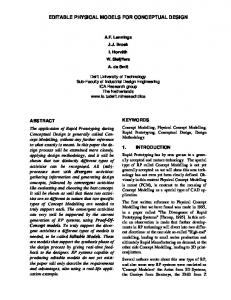
Units-check support for developers covers the following activities: • Marking variables with units • Unit conversion • Checking a model for consistent use of units • Extending the units library • Extending the units system • Integrating user-implemented operators (native SCADE and imported C functions) Marking Variables with Units The units-library contains a continuously expanded set of predefined aliases for the real data type. Wherever a variable is a physical quantity, the corresponding unit data type is to be used instead of real.
Fig. 1. Dialog window for selecting a predefined unit data type for a variable.
To profit from the checking script, only inputs and outputs of the root node and all used constants need to be unit-typed. However, it is good style to do the same for the inputs and outputs of all subnodes if they represent certain physical quantities. Through the use of individual data types, unit information is documented directly in the model and improves the maintainability of the model. No changes to the program function are introduced due to SCADE’s notion of the units as “compatible” data types to real. Unit Conversion Scaling and unit conversion is done manually by multiplication with or division by the scaling constants contained in the unit library. (See second example). Some solutions for unit support in other languages implicitly convert units when necessary. This is not easily implemented in SCADE and would break the requirement of minimum disturbance by massively changing the executed code.
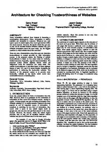
Checking a Model for Consistent Use of units The checking function is integrated into the SCADE development environment as an analysis report for either a single node or all nodes of the project. This is quite similar to the SCADE quickcheck function for checking model consistency; therefore, SCADE application developers are familiar with the concept. The checking function is a tcl script using SCADE’s extension mechanism. The checking function walks through the entire model and for each operator derives the unit of the output(s) from the unit of the input(s). Conflicts for the operator inputs and conflicts between the developer defined and the derived units of the nodes outputs are reported as errors. Extending the Units Library Units not contained in the library can be easily added in the development model or an own library by the user. Unit data types are defined as aliases for real with an added unit annotation. A dialog for unit annotations is shown in the left hand side of figure 2.
Fig. 2. View of an example units library and the unit annotation for milliseconds.
Extending the Units System The checking script is implemented in a generic way. If a new basic unit is needed or the used unit system should be changed, the annotation type definition for units can be changed without touching the script itself. Additional units (e.g. for memory size) can be introduced by adding fields with names in the form: _exponent . If wanted, but at the loss of use for the provided unit library, a unit system with completely different base units could be built by removing/renaming the existing unit exponent fields.
Integrating User-implemented Operators Each modelled SCADE node is itself an operator usable for the modelling of other higher level models. Native SCADE operators Operators (nodes) defined in SCADE are transparently traversed by the checking script. Imported C functions, called imported operators, cannot directly be checked like normal SCADE nodes. If inputs and outputs have unit types associated, unit compatibility will be checked there. For imported operators operating on generic data types or plain reals, the developer can provide a tcl script calculating the output units from the input units and raising error messages.
4
Examples
For demonstration we use the node shown in figure 3, calculating an average speed in m/s, from a given number of wheel axle rotations per execution cycle (ticks). The wheel circumference, the execution cycleduration and the cyclenumber of the average time window are defined in constants. As a test scenario, the units for circumference and cycleduration differ from the units assumed by the model (cm vs. m and ms vs. s).
Fig. 3. SCADE node “avg_speed“
The data type one represents a “dimensionless” type compatible with the other unit types. As you can see, no further unit information is given for the internal variables (the “wires”) – SCADE implicitly derived the types for _L14, _L34, _L35 and _L36 from the respective sources. A first run of the units-check Data gives a result containing (among others): unit determination error
circle in type propagation for _L22 - please set manually
This is caused by back feeding the delayed value _L22 to its own input values. The current algorithm recognizes circles; better heuristics for resolving them with less or without user interaction are possible but not implemented yet.
After manually naming _L22 to dist and setting the type to meters, the units-check result looks as shown in table 1, containing 4 distinct error messages. Table 1. Check result for the node “avg_speed”, after manually resolving the propagation circle eqBlock
eq_avg_speed_2_1
Context
Message Type
Message
L19 = L15 + dist
input unit mismatch
Error – units for inputs differ while they are expected to be identical
L21 = L19 _L17
input unit mismatch
Error – units for inputs differ while they are expected to be identical
dist = fby( L21, 1, 0.0)
unit mismatch error
Conflicting Units single {0 1 0 0 0 0 0 1.000000} and unknown
speed = _L26
unit mismatch error
Conflicting Units single {0 1 -1 0 0 0 0 1.000000} and single {0 1 -1 0 0 0 3 1.000000}
The input mismatch for the addition _L19 = _L15 + dist through the multiplication for _L15 is caused by circumference having the wrong prefix (cm instead of m). This can be corrected either by changing the unit and the value of circumference or in the model by division of circumference through the scaling constant for centi. The next two messages are due to error propagation. If the resulting unit cannot be determined, the unit “unknown” is used for further propagation. For _L21 this means that _L17 and unknown are different (message 2). The manually set unit of dist is in conflict with the unknown unit propagated from _L21 in the third message. Solving the mismatch for _L19 takes care of all these three error messages.
Fig. 4. Example node “speed_limit” using the node from the first example showing unit conversions and comparisons The last error message tells that the derived unit for _L26 is not the same as expected for speed because of its data type m_per_s. In a small model like this example, this error is easily traced back to the unit for cycleduration. In larger models, it can be
helpful to explicitly set intermediate unit information as done above for _L22 to narrow down the possible cause of a unit error. The second example shown in figure 5 makes use of the first example as a subnode. The calculated speed in m/s is converted to miles per hour and kilometres per hour; the converted values are compared to two speed_limit inputs. In the model as shown, the speedlimit-inputs have data type real and therefore no unit information associated. This gives the units-check result shown in table 2, easily leading to the missing units information for the speed_limit inputs. The used conversion factors are defined in the unit library. The factor_3_pt_6 has an own unit data type by_3_pt_6, having all fields of the unit annotation except the scaling factor set to zero. The scaling factor is set to 0.2778, the reciprocal of the constants value 3.6. Table 2. Check result for the node “speedlimit” eqBlock
Context
Message
L16 = L4 > L12
Error – units for inputs differ while they are expected to be identical
L17 = L13 < L6
input unit mismatch
Error – units for inputs differ while they are expected to be identical
speedlimit : real
unit determination warning
Units information not retrievable / not given for input/hidden input
us speedlimit : real
unit determination warning
Units information not retrievable / not given for input/hidden input
eq_speedlimit_1
5
Message Type input unit mismatch
Related Work
Since the problem area is well known and widespread throughout application domains, there are various tools and libraries for units support. Some theoretical work was already done in 1978 [10] and before. Languages and tools with available, but sometimes rudimentary, unit libraries are, among others: Ada4[9], C5, C++ [3,18], Excel [1], Fortran-906[12], Java7, Lisp[4], MatLab8, and Visual Basic9. The main feature sets found are: explicit conversion, implicit conversion, documentation, runtime-check, compile-time (or other development-time) check and unit inference. With the exception of C++ and Ada, the mentioned libraries support only runtimeevaluation (of a subset) of calculation correctness or are even limited to mere conver4
http://www.dmitry-kazakov.de/ada/units.htm http://www.unidata.ucar.edu/software/udunits 6 http://rain.aos.wisc.edu/~gpetty/physunits.html 7 http://nanotitan.com/software/Libraries/quantity 8 http://www.mathworks.com/matlabcentral/fileexchange/loadFile.do?objectId=10070, http://www.mathworks.com/matlabcentral/fileexchange/loadFile.do?objectId=6850 9 http://www.entisoft.com/ESTools/Units.HTML 5
sion helpers. In dependable embedded systems, though, unit information is usually not dynamic and therefore unit correctness can and should be treated at development time. This avoids related runtime overhead as well as the resulting runtime errors. For C++, this can be achieved by using template metaprogramming, resulting in compile time error messages for unit errors. This usage of templates is increasingly often used as an example in the teaching of C++ templates and multiple implementations of various degrees of maturity are available, e.g. the SIunits library and the open source project Quantities10. [3] gives a good description of the general approach and details of implementation in the SIunits library. Guo and McCamant [7] describe a different approach for C: In large (especially legacy) programs it is difficult to “annotate” each and every variable and constant with the correct unit information. To help with this problem, they propose an analysis tool that infers a set of unit types based on the usage of variables and constants in the program. This allows some consistency checks without further programmer intervention and can help a programmer annotating variables and constants. For a pre-existing open source utility with more than 50000 lines of code, they could reduce the 11000 program variables to 163 basic units requiring unit annotation.
6
Conclusion
An approach for checking SCADE models for correct usage of physical dimensions has been presented which provides the following benefits: Development-time error recognition – and, as a result, keeping unit error discovery independent from test data and test methodology, and avoiding runtime overhead. Ease of Use – by providing libraries of predefined units, a convenient way to use them and complete integration of the toolset into the development platform. Minimum disturbance – other SCADE features, including code generation and model checking, remain unaffected. Retro-applicability – can be applied to existing models by only setting input, output and constant units in the model itself or a wrapper node or by simply using the model as a subnode in a unit marked model. Extensibility and generic implementation – by allowing definition of new units and even extensions/changes to the unit system used (e.g. by adding “memory units”). Of course, it should be noted that several limitations have to be considered. There is the possibility to have ambiguity on scaling factors and exponents (100*103 vs. 1 * 105) and problems with computational accuracy when scaling factors are used intensively. Therefore, future work will address these topics, as well as trying to further improve the usability e.g. by automatically resolving unit propagation circles and showing derived units in the block diagram. Also, future extensions of SCADE like for
10
http://www.echem.uni-tuebingen.de/~bs/AKhomepage/Quantities/quantities.html
matrix handling will be considered, possibly together with a major extension of the functionality to support orientational analysis. Finally, it will be investigated whether the taken approach can be migrated to other platforms like e.g. Simulink. As concluding remark, it can be stated that tools like that described in this paper are helpful for avoiding software development errors and thus important means for the verification of software. Acknowledgements The Authors would like to thank Esterel Technologies expert Jean-Louis Colaço for proof reading this paper.
7
References
1. Antoniu, T., Steckler, P., Krishnamurthi, S,.et al.: Validating the unit correctness of spreadsheet programs. In ICSE’04, Proceedings of the 26th International Conference on Software Engineering, pages 439–448, Edinburgh, Scotland (May 26–28, 2004) 2. Bouali, A., Dion, B., Konishi, K. : Using Formal Verification in Real-Time Embedded Software Development. Japan SAE, Yokohama, 2005 3. Brown, W.E.: Applied template meta-programming in SIunits: the library of unit-based computation. In: Proceedings of the Second Workshop on C++ Template Programming, Tampa Bay, FL, USA (October 14, 2001) 4. Cunis, R. 1992. A package for handling units of measure in Lisp. SIGPLAN Lisp Pointers V, 2 (Apr. 1992), 21-25. 5. Dion, B., Gartner, J.: Efficient Development of Embedded Automotive Software with IEC 61508 Objectives using SCADE Drive. 6. DO-178B: Software Considerations in Airborne Systems and Equipment Certification., RTCA/EUROCAE (1992) 7. Guo, P., McCamant, S.: Annotation-less Unit Type Inference for C. Final Project, 6.883: Program Analysis, CSAIL, MIT (December 14, 2005) 8. Halbwachs, N., Caspi, P,. Raymond, P, and Pilaud, D.: The synchronous dataflow programming language lustre. Proceedings of the IEEE, 79(9):1305–1320 (September 1991) 9. Hilfinger, P.N.: An Ada package for dimensional analysis. ACM Transactions on Programming Languages and Systems (TOPLAS), v.10 n.2, p.189-203 (April 1988) 10.Karr, M. and Loveman, D. B. 1978. Incorporation of units into programming languages. Commun. ACM 21, 5 (May. 1978), 385-391. 11.Mars Climate Orbiter Mishap Investigation Board. Phase I report (November 1999) 12.Petty, G.W. : Automated computation and consistency checking of physical dimensions and units in scientific programs. In: Software - Practice and Experience, 31, 1067-1076 (2001) 13.SCADE Suite Technical and User Manuals, Version 5.0.1, June 2005, Esterel Technologies 14.Système International d'Unités, http://www.bipm.fr/en/si/ 15.Siano, D.: Orientational Analysis - A Supplement to Dimensional Analysis - I. J. Franklin Institute (320): 267. (1985) 16.Siano, D.: Orientational Analysis, Tensor Analysis and The Group Properties of the SI Supplementary Units - II. J. Franklin Institute (320): 285. (1985) 17.Using Simulink, Version 6, 2005, The MathWorks 18.Umrigar, Z. D: Fully static dimensional analysis with C++. SIGPLAN Not. 29, 9 (Sep. 1994), 135-139.