CIRAS-1 PORTABLE PHOTOSYNTHESIS SYSTEM Troubleshooting & Service Guide V. 1.10 ©
1999 PP Systems. All Rights Reserved PP Systems 110 Haverhill Road Suite 301 Amescury, MA 01913 USA. Tel: +1 978 834 0505 Fax: +1 978 835 0545 Email:
[email protected]
October 7, 2003
CIRAS-1 Troubleshooting & Servicing Guide
Table of Contents Page No: 1.0. 1.1.
Introduction. Returning Equipment to PP Systems for Service.
1 1
2.0. 2.1. 2.2. 2.3. 2.4. 2.5. 2.5.1. 2.5.2. 2.5.3. 2.5.4. 2.5.5. 2.5.6. 2.5.7. 2.5.8.
Routine Maintenance. Daily Maintenance Schedule. Monthly Maintenance Schedule. Annual Maintenance Service. Tools Required for CIRAS-1 maintenance. Routine Servicing. Chemicals. Absorber Columns. CO2 Regulator. Inlet Filters. Battery. Pumps. Water Vapour Equilibrator. Leaf Cuvettes.
3 3 4 4 4 5 5 6 6 7 8 8 10 10
3.0. 3.1. 3.2. 3.3. 3.4. 3.5. 3.6. 3.7.
Troubleshooting CIRAS-1 Problems. First principles. Testing the CIRAS-1 as a CO2 / H2O Analyser Only. Problems Normally Associated with the CIRAS-1 Analyser. Testing the CIRAS-1 Analyser with the Integral Cuvette Air Supply. Problems Normally Associated with the Integral Cuvette Air Supply. Testing the Leaf Cuvette with the CIRAS-1 System. Problems Normally Associated with Leaf Cuvettes.
11 11 11 12 13 15 17 18
4.0. 4.1. 4.2. 4.2.1. 4.2.2. 4.2.3. 4.2.4. 4.2.5. 4.2.6.
CIRAS-1 Initialisation & Diagnostics features. Initialisation. Diagnostics. Identifying Instrument Firmware Version. Diagnostics in Firmware Versions Before 4.0. Additional Features After Version 2.0. Diagnostics in Firmware Version 4.0. or Greater. Changing the CIRAS-1 Operating Mode During Diagnostics. Testing the Control Features of the Automatic Leaf Cuvette.
20 20 20 21 21 23 23 25 25
5.0. 5.1. 5.2. 5.3. 5.3.1. 5.3.2. 5.4.
CIRAS-1 Calibration. Checking CIRAS-1 Calibration. CO2 Calibration. H2O Calibration. The Water Vapour Calibrator. Water Vapour Calibrator Maintenance. Setting the CO2 Midpoint for Units with Automatic Air Supply.
27 27 28 29 29 30 30
© 1999, PP Systems
Page i
CIRAS-1 Troubleshooting & Servicing Guide
6.0. 6.1. 6.2.
Error & Warning Messages. Warning Messages. Status & Error Codes.
32 32 35
7.0. 7.1. 7.1.1. 7.2. 7.3. 7.4. 7.4.1. 7.4.2. 7.4.3. 7.5. 7.5.1. 7.6.
User Serviceable Parts. Main Air Supply Pump. Replacing the Main Air Supply Pump. CO2 / H2O Diverter (Manual CIRAS-1 Instruments). CO2 Gas Blender Assembly (Automatic CIRAS-1 Instruments). CO2 Regulator. Testing the CO2 Regulator. Removing the CO2 Regulator. Inserting a Replacement CO2 Regulator. EPROMS. Replacing EPROMS. Fuses.
37 37 37 38 38 39 40 40 41 42 42 43
8.0. 8.1. 8.2. 8.2.1. 8.2.2. 8.2.3. 8.2.4. 8.2.5. 8.3.
Leaf Cuvettes. Opening the Cuvette Head For Gasket Removal. Servicing Standard Cuvette Systems. Replacing the Impeller Blade. Replacing the Cuvette Fan. Replacing the Impeller Motor. Replacing Cuvette Tubing. Checking the Calibration of the PAR Sensor. Measurement of Boundary Layer Resistance (Rb).
44 44 44 45 45 45 45 46 47
9.0. 9.1. 9.1.1. 9.1.2. 9.1.3. 9.1.4. 9.1.5. 9.2. 9.2.1. 9.2.2. 9.2.3. 9.2.4.
Cuvette Light Units. Standard Light Units. Fitting the Light Unit. Lamp Power Supply. Controlling the Light Intensity. Determining the Cuvette Light Intensity. Replacing Lamp Bulbs. Automatic Light Units. Fitting Automatic Light Units. Lamp Power Supply. Replacing Lamp Bulbs. Replacing Cooling Fans on Automatic Light Units.
48 48 48 48 48 48 49 49 49 49 49 51
Appendix A. Appendix B. Appendix C. Appendix D.
52 54 55 57
© 1999, PP Systems
Page ii
CIRAS-1 Troubleshooting & Servicing Guide
1.
Introduction
The CIRAS-1 Portable Photosynthesis System went into manufacture in the autumn of 1992. Over the past seven years it has proven to be an extremely reliable instrument assisting hundreds of scientists from around the world with their research. Throughout this period we have accumulated considerable experience with regards to the reliability and performance of the system. This service guide has been prepared to pass on this experience and assist users with troubleshooting and servicing of their equipment. Hopefully this guide will equip a competent user or technician with the skills to diagnose the common problems, service and maintain all of the CIRAS-1 consumable parts. The guide is divided into the following sections: • • • • • • • •
Routine Maintenance, Troubleshooting CIRAS-1 Problems, CIRAS-1 Initialisation and Diagnostic Features, CIRAS-1 Calibration, Error and Warning Messages, User Serviceable Parts, Leaf Cuvettes, Cuvette Light units
Repair of CIRAS optical bench requires specialist tools and factory based re-linearisation of their performance. In this event, the instrument should be returned to PP Systems. Details for returning equipment are shown below.
1.1. Returning Equipment To PP Systems For Service When returning equipment to us for service or repair, it is critical that the equipment is properly packed up and that the documentation is complete and accurate for customs purposes. PP Systems is not responsible for any customs charges such as import duties, VAT, etc., that could apply as a result of incorrect documentation. Please note the following: Packaging and Documentation. Notes on Packing Equipment. • Please ensure that the equipment is safely packed in bubble wrap or similar packaging material. • If not using the original packing box, ensure that the box is sturdy and proper parcel sealing tape is used. We recommend using at least a double walled box. • Make sure that the equipment is surrounded by impact absorbent packing inside the box. • The equipment MUST be insured. We recommend using the purchase price of the system as the insurance value. • Advise us in writing (by fax or e-mail) as to how and when the equipment was shipped. Paperwork. Enclose a detailed letter stating: • Full name and address (including telephone number, email etc.) of contact person responsible for returning the equipment. • Whether or not the equipment is covered under warranty. • Description of fault(s) including anything you may have done to the instrument prior to the problem. • Required return date of the equipment. Please discuss this with PP Systems prior to shipping. Return of Equipment to Our UK Office.
© 1999, PP Systems
Page 1
CIRAS-1 Troubleshooting & Servicing Guide
When returning equipment to the UK for repair or upgrade, the following declarations must be clearly stated on the commercial invoice and airway bill for customs purposes: • • • •
Temporary export to the UK from (country it is coming from) of goods for repair/upgrade. NOT FOR RESALE Zero commercial value. Value for insurance purposes only: (Amount defined by you).
When returning equipment that we have loaned to you, the following declaration must be clearly stated on the commercial invoice and airway bill for customs purposes: • Return of UK goods after temporary loan. • Zero commercial value. • Value for insurance purposes only: (Amount defined by you). Return Of Equipment to Our USA Office. When returning equipment to the USA for repair or upgrade, the following declarations must be clearly stated on the commercial invoice and airway bill for customs purposes: • • • •
Temporary export to the USA from (country it is coming from) of goods for repair/upgrade. NOT FOR RESALE Zero commercial value. Value for insurance purposes only: (Amount defined by you).
When returning equipment that we have loaned to you, the following declaration must be clearly stated on the commercial invoice and airway bill for customs purposes: • Return of USA goods after temporary loan. • Zero commercial value. • Value for insurance purposes only (Amount defined by you). In addition, include a copy of the original invoice and our carrier’s airway bill with the shipment for customs purposes. PP Systems has offices located in both the United Kingdom and United States. All packages should be addressed to one of the following:
Tel: Fax:
In Europe
In North America
PP Systems Unit 2, Glovers Court Bury Mead Road Hitchin, Herts SG5 1RT UK +44 (0) 1462 453 411 +44 (0) 1462 431 090
PP Systems 110 Haverhill Road, Suite 301 Amesbury, MA 01913 U.S.A.
Email:
© 1999, PP Systems
+1 978 834 0505 +1 978 834 0545
[email protected]
Page 2
CIRAS-1 Troubleshooting & Servicing Guide
2.
Routine Maintenance
The CIRAS-1 is a sophisticated piece of equipment that is often operated under sub-optimal environmental conditions. It is therefore sensible to establish and follow a planned schedule of maintenance. The degree of maintenance required is determined by the extent of instrument use and the ambient operating conditions. However, PP Systems recommend the following schedule as a starting point.
2.1. Daily Maintenance Schedule. Before Making Measurements: A.
Check that the absorber chemicals are fresh, all of the absorber columns are properly sealed and inserted into their respective manifolds (Section 2.5.1.).
B.
Before going out to the field: connect the PLC, connect charger (to avoid draining battery), switch on the instrument and allow it to fully warm-up (30 minutes). Set the reference CO2 control to zero. The REF CO2 value should decrease to less than 10 ppm and remain steady. Remove dead cylinder, assuming at least 24 hours have elapsed. Replace with new cylinder. Set the CO2 control to the desired measurement value and check that it is maintained. Section 3.4. contains information on troubleshooting the CIRAS CO2 control system.
C.
Check that the gaskets on the PLC (if used) are in good condition. Close the chamber without a leaf and run the system for two minutes. Check that the CO2 and H2O differentials stabilise at 000 (+/- 1) ppm. Section 3.7. contains information in troubleshooting cuvettes.
After Making Measurements: A.
Disconnect both the electrical and pneumatic connections to the cuvette from CIRAS.
B.
Check that the cuvette is clean and leave the jaws open so that the gaskets have a chance to recover and do not become crushed over-night.
C.
The CO2 cartridge MUST be left in place over night to discharge safely whilst the instrument is switched off. Avoid leaving the CIRAS in a bag, otherwise the CO2 from the cartridge will build up in the absorber columns. This will cause premature exhaustion of the chemicals and slower instrument warm-up as excess CO2 is flushed the next day.
D.
Place the CIRAS battery on the battery charger over night. Before leaving the instrument it is sensible to check that the red lamp on the charger unit is illuminated. This indicates that the battery is drawing current. It is important to charge the battery over night before storing the instrument for any significant period of time. If CIRAS is out of use for long periods then it is recommended that every month the unit is switched on and left to run for a couple of hours and that the batteries are recharged.
© 1999, PP Systems
Page 3
CIRAS-1 Troubleshooting & Servicing Guide
2.2. Monthly Maintenance Schedule. A.
Check the air supply and inlet filters (Section 2.5.4.). These should be white; if they appear dirty they need to be replaced (Section 2.5.4.).
B.
Check the air supply pumps (Section 2.5.6.) and if the instrument is subject to heavy use, clean the pumps (Section 2.5.6.).
2.3. Annual Maintenance Service. PP Systems offers an Annual Preventative Maintenance (APM) service for CIRAS . This includes: • • • • •
Inspection of all internal plumbing, Inspection / replacement of all O-rings, Replacement of all filters, Replacement of all chemicals, Electrical check, inspection and full calibration of CO2, H2O analysers and flowmeters.
If a PLC is part of the system the service includes: • • •
Replacement of cuvette gaskets, Replacement of piping (if necessary), Checking and re-calibration of sensors.
Please consult with PP Systems or your local agent for more details regarding this service.
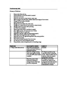
2.4. Tools Required For CIRAS Maintenance. Most of the routine maintenance tasks can be performed with standard tools found in any workshop and the spares that are supplied as standard with your CIRAS system. Certain items, such as a manometer and equilibrator substitute link pipe, for more in-depth repair can often be improvised. However, PP Systems also supply a CIRAS-1 Test Kit (CRS063) (Figure 2-1). The kit contains the following items: Tools & Test Gear
CIRAS-1 Spares
•
• • • • • • • • •
• • • • • • • • • • •
Manometer- used in conjunction with the syringe for leak testing. Flowmeter- low resistance float type for monitoring CIRAS air supply and sample flows. Flat blade screwdriver (4mm) Posidrive screwdriver (Size 1) Knife with snap-off blades Potentiometer trim tool Snipe nose pliers with smooth jaws for removing and replacing rubber pipes O-ringhook -a flattened bent wire for easily replacing the CO2 regulator “O-rings” Syringe Multimeter (Optional) Equilibrator substitute link pipe Socket with pipe connector for end of equilibrator/absorber tube
© 1999, PP Systems
Page 4
Inlet Filters (6 each) “O” rings for CO2 regulator (6 each) “O” rings for absorber column (3 of each type) CIRAS-1 fuses, 3.15A (or 2A) (5 each) Selection of CIRAS-1 screws Silicone grease Selection of piping Screw in connectors (2 each) Small sinters (2 each)
CIRAS-1 Troubleshooting & Servicing Guide
Tools & Test Gear • • • • •
CIRAS-1 Spares
Rubber plug to seal off absorber manifold sockets Pipe to cross-link absorber tubes Plastic T-pieces (2 each) Pipe reducers (2 each) Pump/valve test lead (elect)
Figure 2-1. CIRAS-1 Test Kit (CRS063)
2.5. Routine Servicing. The CIRAS-1 uses a number of consumable chemicals and parts during operation. This section covers replacement and servicing of these items under routine conditions. More detailed trouble-shooting and repair information is included in subsequent chapters. 2.5.1. Chemicals. The CIRAS-1 uses three different chemicals to condition the instrument air-supply: Soda Lime. Soda lime is used to remove CO2 from air entering the CIRAS-1. It is supplied as self-indicating granules (1-2.5mm) which turn from green to brown as they become exhausted. The contents of the absorber column should be replaced when they are two-thirds exhausted (Section 2.5.2.). Soda Lime cannot be regenerated. Drierite. Drierite is used to scrub water vapour from the air supply during zeroing and operation with sub-ambient water vapour control settings. Drierite is supplied as blue granules that turn pink when exhausted. Columns should be replenished when two thirds of the chemical is exhausted (Section 2.5.2.). Drierite can be regenerated by baking in an oven at 200 °C for 1 hour. A single layer of granules should be spread on a tray. (this minimises colour loss, which is due to the loss of cobalt chloride by sublimation and by migration into the centre of granules). The drying power remains unaffected but the indicator colour becomes less intense. It is therefore sensible to mix re-used drierite with some fresh material to show when it is exhausted. Molecular Sieve. Molecular sieve is used to finally filter any remaining CO2 and H2O from the air supply during zeroing and from the water vapour control circuit. Unfortunately molecular sieve is not self-indicating and there is no obvious way to see that it is exhausted. It is therefore best to change the molecular sieve when changing your other chemicals. Please note that there is no foam pad at the molecular sieve end of the drierite / sieve column so extra care must be taken when changing this column. Molecular sieve can easily become contaminated through absorption of CO2 and H2O from atmospheric air. It is therefore strongly recommended that molecular sieve is decanted into small air-tight containers to minimise any exposure to air. The molecular sieve columns should be placed in a sealed polythene bag if they are removed from the CIRAS-1.
© 1999, PP Systems
Page 5
CIRAS-1 Troubleshooting & Servicing Guide
2.5.2. Absorber Columns. The absorber columns should be removed from the CIRAS-1 by pulling the columns off their respective manifolds. Care should be taken to gently pull both ends of the column out together. After the column has been removed one of the end-caps can be removed to release the contents. It is sensible to examine the absorber columns each time the contents are replaced as any leakage of ambient air into the gas circuits generally causes error messages during “Autozero” operation or fluctuating reference CO2 concentration during measurement. There are three items that should be checked after re-filling a column: Foam Pads. The foam pads become worn over time and should be inspected regularly and replaced when torn or reduced in size. The foam must be of an open celled type, such as packing foam. Absorber Filters. Each absorber end cap contains a white plastic filter disc. Generally these do not need to be replaced. However, they must be present to prevent any of the column contents being drawn with the gas stream into the instrument. O-rings. The O-rings on the end caps of the columns should be very lightly smeared with silicone grease to aid ease of fitting and improve the seal. Once sealed, end fittings should be checked to ensure that the O-rings are seated correctly in their groove and that they are not trapped or pinched. There is also a small O-ring on each of the absorber end cap fittings. These seal the absorber column into the CIRAS manifolds. These should be in good condition. Replacement O-ring and filter sets can be ordered from PP Systems (Part Number STD017). 2.5.3. CO2 Regulator. The CIRAS-1 Portable Photosynthesis System contains an internal air-supply unit that is used to control the CO2 concentration of the reference gas supply. The CO2 is supplied from a disposable cartridge that is inserted into a regulator on the side of the instrument. Before inserting a fresh cartridge it is always sensible to check that the O-ring inside the regulator is properly seated. It can be deformed during accidental rapid discharge of the cylinder. If this is the case it must be replaced (Part Number STD037). It is also useful to roll the neck of the cylinder between thumb and forefinger. This places a thin layer of grease around the neck of the cartridge, which helps to provide a good seal. Please note – once a CO2 cylinder has been inserted, it takes 24 hours for it to discharge. The cylinder should ONLY be removed after this time has elapsed. There are two methods to check whether there is a charged cartridge in the instrument. Method 1. Switch on the CIRAS-1 and allow it to warm it up. Set the CO2 control to deliver 2,000 ppm CO2 (automatic systems) or turn the diverter control knob fully clockwise (manual systems). The air-supply unit should deliver a stable reference CO2 concentration of approximately 2,000 ppm CO2. If the CO2 concentration slowly declines (or fails to reach the set value) it is likely that the CO2 cartridge is discharged (or sufficiently discharged for safe removal). However, before removing, it is best to re-check using method 2. Method 2. © 1999, PP Systems
Page 6
CIRAS-1 Troubleshooting & Servicing Guide
The air-supply unit vents excess CO2 to an exhaust port. This is located on the side of automatic units, beneath the CO2 regulator itself. Manual units (which have diverter control knobs beneath the regulator) have the exhaust in the base of the unit near the battery compartment. Switch off the CIRAS-1 and attach a 30 cm piece of tubing to the exhaust port. Briefly insert the tubing into a beaker of water; a steady flow of bubbles (approximately 3-4 ml min-1) will be observed if the cartridge is charged. If there are no bubbles the CO2 cartridge is probably discharged. Please note - it is important that the CIRAS-1 is switched off during this test to ensure that there is no possibility for water to suck back into the instrument. 2.5.4. Inlet Filters. The CIRAS-1 air supply section and analyser optics are protected by three 5.0 µm air inlet filters. These are located inside the air-inlet manifold, which is next to the “PLC” electrical connector on the CIRAS-1. The following procedure can be used to access the filters: 1. 2. 3.
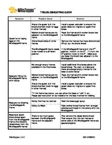
Place the CIRAS on a flat table with the “PLC socket and gas fittings facing upwards. Remove the absorber columns. Identify the plate covering the inlet manifold (Figure 2-2.).
Figure 2-2. Location of Inlet Filter Plate and retaining screws. 4.
Remove the four cross-head screws that secure the plate to the manifold (Figure 2-2).
5.
Gently prise the plate upwards with a flat blade screwdriver until it can be gripped and pulled off with fingers. N.B. the plate is sealed in place with O-rings. It may require a little force to remove it.
6.
The filters are white paper-like polypropylene discs at the bottom of the manifold recesses; they should be white (Figure 2-3).
© 1999, PP Systems
Page 7
CIRAS-1 Troubleshooting & Servicing Guide
Figure 2-3. Inlet Filters. 7. 8. 9.
If they appear dirty they should be replaced (Part Number STD004). Blocked filters will impede the air-flow to the cuvette air supply and cause the CO2 concentration of the reference gas to fluctuate. The filters may be removed by lifting them up with a fine screwdriver and replaced by lowering a new filter into position with tweezers. Inspect the O-rings around the manifold gas entries and re-fit the manifold covering plate with screws. A very light smear of silicone grease can be used to lubricate the O-rings and ensure a good seal.
2.5.5. Battery. The CIRAS-1 12 V 2.0 Ah lead-acid battery should be checked periodically to ensure that it takes up charge. Measuring the voltage across the terminals of the battery after it has been charged over-night can assess this. If the battery is not fully charged after 12 hours, check the 5 A fuse (manual CIRAS-1 units) or 3.15 A fuse (automatic CIRAS-1 units) that is located in the base of the CIRAS-1. This fuse protects the charging circuit; if it is blown the internal battery will not take a charge. Please Note – the batteries should be fully charged before long-term storage. If they are stored in a discharged state it is possible that they will become deep-discharged. If this occurs the charge capacity of the battery is permanently reduced. 2.5.6. Pumps. The CIRAS-1 Analyser section uses two rotary vane pumps, one to sample Reference air and the other to sample Analysis air. The CIRAS-1 Air Supply section uses two rotary vane pumps for Air Forwarding and additionally, in automatic CIRAS-1 units, one diaphram pump providing the Main Air supply flow Rotary vane pump components wear with prolonged use and material from the vanes may build up within the pumps. This can eventually reduce the pumping efficiency or even cause them to seize. If this happens the rate of airforwarding is insufficient for the gas blender and the CO2 concentration in the reference flow will fluctuate. The risk of this situation occurring can be minimised by regular pump servicing. The pumps used for Reference, Analysis and Main Air supply (Auto only) do not require regular maintenance (flowmeters monitor their performance). Opening CIRAS and Locating the Air Forwarding Pumps. 1. 2. 3. 4. 5.
Switch off and place the CIRAS-1 on a flat table with the “PLC socket and gas fittings facing upwards. Remove the absorber columns, placing any columns containing molecular sieve into sealed polythene bag to minimise its exposure to ambient air. Remove the four plastic screw covers from the case using a small, flat bladed screwdriver. Remove the four cross-head) screws that retain the case. Gently lift up the case from both sides. The case may stick where the equilibrator plugs into its manifold. If necessary lift the case between the LCD display and keypad as well as the sides.
© 1999, PP Systems
Page 8
CIRAS-1 Troubleshooting & Servicing Guide
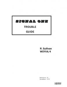
A row of four pumps should be visible to the left, above the air-inlet manifold (Figure 2-4). The two pumps at the base of the instrument are the Air Forwarding pumps (Figure 2-4); they are labeled IN PMP on the CIRAS Flowmeter board. A worn or faulty pump normally displays some the following symptoms when the CIRAS-1 is switched on.
Figure 2-4. Pump locations within CIRAS-1. 1. 2.
Noise – a worn pump usually sounds rough or vibrates. Temperature – the outer casing (near the pump serial number) feels warm compared to other pumps.
It is also important to check that both the electrical and gas connections to the pumps are satisfactory. Removing a Pump. It is very easy to remove a pump for servicing. First, trace the electrical connection to the pump and disconnect the 2-pin connector from the terminal on the CIRAS-1 Flowmeter board. The connector is removed by gently bending back the connector lock and sliding out the connector. Please note the orientation of the red and black wire for correct re-fitting of the pump. The pump itself is secured in position by the gas connections. These are un-done by gently pulling the pump from the rubber connections. Servicing a Rotary Vane Pump. During pro-longed operation the vanes inside the pump will wear and deposit material inside the pump. It is sensible to clean the pump by flushing it through with iso-propyl alcohol. The following procedure can be adopted: 1.
Connect the pump to a 6-12V source and fit a 30mm tube to the pump inlet. (N.B. the CIRAS-1 can be used to supply power via the pump electrical connector. It is, however, essential that the flushing is done outside of the CIRAS-1 to avoid spillage into the instrument).
2.
Hold the pump above a beaker of iso-propyl alcohol and dip the tube into the alchol (Figure 2-5). Run the pump to draw alcohol through it. A small roll of cotton wool in the inlet pipe can act as a filter for the recirculating alcohol.
© 1999, PP Systems
Page 9
CIRAS-1 Troubleshooting & Servicing Guide
Figure 2-5. Flushing a pump with ethanol. If the pump is seized it may be freed by tapping it on the bench or by reversing the voltage to run it backwards. 3.
Run alcohol through the pump for a minute or two to ensure that any material is removed. Please note that the CIRAS-1 pumps are not sealed, so it is normal to see alcohol leak through the sides of them during this procedure. When finished, run the pump in air for at least 15 minutes to allow any residual alcohol to evaporate. Ideally, let the pumps dry outside of the CIRAS-1 overnight. If the pumps are reconnected prematurely, the absorber chemicals will be exhausted quicker than usual.
Fitting Pumps. The pumps are held in place by the santoprene gas connectors which join the pump inlet and outlet connectors to the CIRAS-1 gas circuit. These should be connected with the flat back of the pump oriented flush with manifold. The 2pin electrical connector should be re-connected. The two notches on the connector latch with the corresponding lock. 2.5.7. Water Vapour Equilibrator. Periodically inspect and confirm that the equilibrator is pushed firmly into its manifold and that all of the internal tubing is seated properly in the equilibrator blocks. 2.5.8. Leaf Cuvettes. The leaf cuvette should be routinely checked, after use, for debris such as dirt, broken off leaves / needles, etc. If debris are found they should be removed carefully with a soft brush or lint-free cloth. The cuvette head should be stored in an open position. This prevents the gaskets from becoming permanently crushed. The gaskets should be regularly inspected for leaks and tested by running the system with the heads closed and no leaf present in the chamber. Under these conditions the CO2 and H2O differential should be 000 (+/- 1 ppm). Breathing around the cuvette should not result in an increase in the measured differential. Leaks are usually easy to localise by gently blowing around the cuvette through a fine piece of tubing and monitoring the position that results in a large differential measurement. Further cuvette troubleshooting is available in section 3.7..
© 1999, PP Systems
Page 10
CIRAS-1 Troubleshooting & Servicing Guide
3.
Troubleshooting CIRAS-1 Problems.
Regular maintenance should ensure that the CIRAS-1 provides many years of trouble-free operation. However, as with any piece of sophisticated instrumentation, components have a finite life that will vary depending upon the intensity of use and operating environment. The aim of this chapter is to aid the operator in identifying the cause of any symptoms and where possible resolve the problem on-site.
3.1. First Principles. The CIRAS-1 portable photosynthesis system is actually a number of instruments that have been combined into a single field-portable system. Often a problem with one component will manifest symptoms in other parts of the instrument. This can cause difficulty identifying the source of a particular problem. The best technique to over-come this is to isolate the system components and test each one separately.
3.2. Testing the CIRAS-1 as a CO2 / H2O Analyser Only. Obvious error messages such as Ref/Anal flow to low
Filters/Pumps Pipes off/ Flowmeters read 0.163. Any reading greater than 163 indicates either no flow or flow in the wrong direction through the flowmeter. (Incorrectly inserted pump or reversed connector.) Differential pressure between cells exceeds 15 ml. Sample pipe or filter blockage
Flow to high
DP out of range Refer to Section 6 for error messages.
The CIRAS-1 IRGAs can be tested independently by disconnecting (electrically and gas lines) the leaf cuvette from the system. The reference and analysis ports should be connected together with a “Y” piece connector so they draw in air from a common gas stream (Figure 3-1). Ideally the gas should be of a known constant concentration. However, if this is un-available atmospheric air can be drawn in from a site that is located away from extraneous CO2 sources such as roadways, vents or chimneys etc. It is often useful to pass this through a sealed smoothing volume to minimise fluctuations due to wind or pressure differences.
Figure 3-1. Tubing Connections to Test CIRAS-1 as an IRGA Only.
© 1999, PP Systems
Page 11
CIRAS-1 Troubleshooting & Servicing Guide
It is important to make the connection to the reference port with small-bore santoprene tubing, covering only the small reference inlet. The air supply to the cuvette passes around the small reference inlet via the large outer pipe; this must be left unobstructed (Figure 3-1). Once connected, the CIRAS-1 should be switched on and allowed to warm up for at least half an hour. Select REC from the main menu and progress through the menus until the measurement mode displays readings of both reference and differential CO2 and H2O vapour concentrations. The CIRAS-1 CO2 readings should be steady and match the known CO2 reference source that is feeding into the instrument. In the case of atmospheric air this should be in the range 350 to 400 ppm. The reference H2O reading will depend upon ambient conditions. (Information regarding the calibration of CIRAS-1 can be found in section 5.0.) Both CO2 and H2O vapour differentials should be 0 (+/-