J.W. Christian, G.B. Olson* and M. Cohen** ..... Reid A.C.E. "A Hydrodymanic Theory of Pattern Formation at the Martensite Transition," Ph.D. Thesis, 1994 ...
JOURNAL DE PHYSIQUE IV Colloque C8, suppl6ment au Journal de Physique 111,Volume 5, dkcembre 1995
Classification of Displacive Transformations: What is a Martensitic Transformation? J.W. Christian, G.B. Olson* and M. Cohen** Oxford University, Department of Materials, Parks Road, Oxford OX2 6UT, U.K. * Northwestern University, Department of Materials Science and Engineering, 2225 North Campus Drive, Evanston, IL 60208-3108, U.S.A. ** Massachusetts Institute of Technology, Department of Materials Science and Engineering, 77 Massachusetts Avenue, Cambridge, MA 02139, U.S.A.
Abstract. The displacive transformation classification proposed at ICOMAT 79 [I] is reviewed in light of recent progress in mechanistic understanding. Issues considered include distinctions between shuffle transformation vs. self-accommodating shear, dilatation vs. shear-dominant transformation, and nucleated vs. continuous transformation.
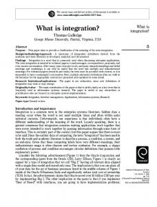
1. HISTORICAL INTRODUCTION Cohen, Olson and Clapp (COC) at ICOMAT-79 defined a martensitic transformation as a sub-category of a wider field of displacive changes [I]. In the intervening 16 years, there has been appreciable progress in understanding martensitic and related transformations, and it now seems appropriate to re-examine the COC criteria in the light of recent experimental and theoretical work on microscopic mechanisms of transformation. To some metallurgists, martensite will always be a particular microconstituent in suitably heat-treated ferrous alloys, whilst others may use the apparently tautological definition, "Martensite is the product of a martensitic reaction." The emphasis on the mechanism of transformation rather than the properties of the product phase began with an important paper by Troiano and Greninger [2], who showed that various kinetic and crystallographic characteristics of a martensitic change are markedly different from those observed in other "nucleation and growth" reactions. Solid state reactions were thus divided into two main groups, but Kurdjumov [3] and Kurdjumov and Maximova [4] soon showed that some of the Troiano-Greninger features (e.g., no isothermal transformation) are not applicable to all martensitic transformations. It was later proposed [5,6] that a change of shape of the product crystals should be an experimental test for a martensitic (or more generally a "displacive" [7] or "military" [8]) reaction. Phase transformations which involve long range diffusion are regarded as reconstructive rather than displacive, but the early work of Garwood [9] showed, and more recent work [lo-111 has confmed, that shape changes occur in some plate-shaped precipitates with substitutional solute contents different from those of their parent solid solutions. These experimental results imply that some transformations requiring diffusion also have displacive character; they are sometimes called "nonferrous bainites," but this can be misleading. To emphasize their mixed characteristics, the term "diffusional-displacive transformations" has recently been suggested [12]. The COC classification scheme for separating martensitic from other displacive transformations is reproduced in Figure 1. Displacive transformations dominated by atomic shuffles rather than by lattice deformation are first eliminated, and only those lattice distortions in which shear strains are more important than dilatational strains are accepted as martensitic. Finally, a division is suggested between true martensites, in which the strain energy has a major influence on the transformation kinetics and product morphology, and quasimartensites with very small lattice deformations, in which transformation may be continuous. Whilst this scheme attempted to minimize the need for detailed mechanistic information, emphasizing instead kinematic and morphological information deducible from relatively macroscopic observation, it has since been suggested that nucleation is an essential characteristic of a martensitic reaction [13]. A concise definition of a martensitic transformation is then a "shear dominant, lattice distortive, diffusionless transformation occurring by nucleation and growth" 1131. Some points worthy of further consideration are (a) the definition of a shuffle and the validity of the distinction between shuffle-dominantand strain-dominant mechanisms, (b) self-canceling microshears which give Article published online by EDP Sciences and available at http://dx.doi.org/10.1051/jp4:1995801
JOURNAL DE PHYSIQUE IV
(3-4
1 DlSPLAClVVDlFFUSlONLESS PHASE TRANSFORMATIONSI I
I
shuffle drsplocements a)trce-dirtortive dieplocrmcnts
supin energy LATTICE- DISTORTIVE
TRANSFORMATIONS
TRANSFORMATIONS
kinetics and morphology not dominuted by
kinetics and morphology dom~natedby
Sr Ti O3 (ferroelastic) a Wb 0 (fornoelectric; KT.& .JS 3 high resistivity)
L-
The separation of the atomic displacements into lattice deformations and shuffles is not always unambiguous; for example, the deformation may apply only to the lattice points with each atom in the motif unit given the same (lattice) displacement, or the atoms might be regarded as embedded in a deformable continuum, so that the various atoms in a motif unit will undergo different lattice displacements. Now consider the well-known mechanism for fccehcp changes in which a dislocation (approximately a Shockley partial) moves through every two close-packed atomic planes of the original structure, converting it into the other structure. This is equivalent to the motion of an interface step, or "transformation dislocation," between planes (say) 1 and 3 in which the slip is entirely between planes 1 and 2. Thus, the whole structural change apparently requires no shuffling. But now consider the lattice deformation to be homogeneous, i.e. produced by the motion of a half-Shockley dislocation through every atomic plane. Every other atomic plane is now correctly placed but the other planes are stacked in intermediate positions, e.g., 4@+C), and to complete the change, these atoms must shuffle into either B or C positions. Although the "no-shuffle" description seems preferable, the distinction is not physically meaningful. A pure shuffle transformation requires that some unit cell of one lattice is almost identical with a cell of the other lattice. Apart from small differences in the spacing of the close-packed layers, this condition is met in various transformations between structures which have different stacking sequences of twodimensional hexagonal atomic nets. In Co-Ni alloys, for example, a cell six atomic ( 111) planes high in the fcc structure is almost identical with a similar cell in the hcp phase, so that a shuffle-dominated transformation may be feasible. If A layers on planes, 0,6, 12 etc. define the cell, and the hcp stacking is ...ABAB..., the required shuffles on planes 2,3,4 and 5 are C+A, A+B, B+A, and C+B respectively. The shuffle vectors may thus be of type ) or & 20%) is the allotropic transformation in tin, where the low temperature (grey tin) form is very difficult to nucleate, and is obtained from bulk samples as a powder or as a severely cracked and crumbling aggregate. The pure dilatational y-a transition in Ce alloys is apparently accomplished displacively without cracking, at least in thin foils [19] but the mechanism is not clear; in pure Ce it is preceded by an incomplete martensitic change from y to a dhcp (P) allotrope. The previously mentioned 6-a transformation in Pu alloys also involves a 20% volume change, but in this case it has been clearly established [15] that a lattice correspondence is adopted involving sufficiently large shear deformations that the invariant line condition is met and the transformation exhibits conventional martensitic IPS characteristics. The case of pure dilatational transformation offers simplifying features for theoretical investigation of some behaviors of general relevance to lattice-distortive transformations. This has been used by Chu et al [20] to perform precise numerical calculations of homogeneous "nonclassical" nucleation behavior near a lattice instability, comparing systems with smooth vs. cusped surfaces of energy vs. strain. Both types of system show decreasing strain amplitude of the critical nucleus as instability is approached, but only the smooth system shows the Cahn-Hilliard divergence of nucleus size and interfacial width. An interesting behavior shown by the dilatational transformation is that the localized deformation of a
nucleus is restrained by nonvanishing elastic shear constants such that the nucleation barrier does not necessarily vanish at the point of dilatational instability. This illustrates a significant role in nucleation of mechanical transformations of elastic constants beyond those directly associated with the primary order parameter of the system. 4. NUCLEATED VS. CONTINUOUS DISPLACIVE TRANSFORMATIONS
The COC classification distinguishes between martensitic and continuous displacive products ("quasimartensitic") in which nucleation is not required since variant domains appear virtually simultaneously throughout the material by continuous strain modulation [21]. This analogue of spinodal decomposition is theoretically possible for a first order transformation if the parent phase approaches a mechanical stability limit where an appropriate elastic modulus changes sign. However, even when the isothermal modulus is negative ,rapid growth of a domain structure may be limited because the reaction is effectively adiabatic, i.e. energy is conserved and the growth rate of a perturbation is constrained by the necessary heat flow. Umantsev and Olson [22] have performed normal mode and weakly non-linear analyses of the dynamics in unstable systems where the homogeneous free energy cp is a smooth function of a strain parameter 5 and of temperature T. The partial second derivatives of this function, ~p c p c ~and ( ~ r r ,define the isothermal and adiabatic moduli, qcc and ( ~ ~ ~ ( 1 -where M ) ~ = ( q ~ ~ )cpcp ~ / cAfter p~ incorporating a strain gradient energy, solutions may be obtained for the amplification factor P as a function of the wave number of the strain modulation, k. Figure 2 is a stability diagram in the plane of ~c vs. qgTwhich is divided into various unstable regions by the plotted values of M, in each region, the schemanc P-krelationship is shown as an insert.
Figure 2: Stability diagram for continuous modulation in unstable systems, showing schematic curves of amplibtion factor $ vs. wave number k [21].
C8-8
JOURNAL DE PHYSIQUE IV
In case (a), O