like the NASA's Mars Exploration Rover. Laprie [1] .... Figure 1: The proposed classification of fault-tolerant design .... acceptance tests: concurrently execute diverse versions with ..... design was used e.g. in Airbus A-320 flight control systems.
Classification of Hierarchical Fault-tolerant Design Patterns Kai Ding, Andrey Morozov, and Klaus Janschek Institute of Automation Technische Universit¨at Dresden Dresden, Germany Email: {kai.ding, andrey.morozov, klaus.janschek}@tu-dresden.de
Abstract—Fault tolerance plays a significant role in the safety-critical system design. Redundancy is the key underlying approach, which enables a system to continue operation under the presence of faults and improves its dependability properties such as reliability and safety. Various fault-tolerant designs, which have been proved consistently effective, have been proposed over the past decades. In existing literature, common hardware and software dependability-oriented architectures are discussed and classified according to their distinctive features, such as passive/active/hybrid hardware redundancy or single/multi-version programming. However, internal conceptual similarities are usually ignored. In contrast, this paper proposes a new classification that organizes existing fault tolerance techniques into a structured pattern system that supports the choice of an appropriate mechanism. More specifically, this paper defines fundamental and implementation-independent patterns and demonstrates that the well-known fault-tolerant designs follow these patterns. Three basic and four combined design patterns are presented, along with the evaluation examples of their reliability properties and common hardware and software implementations. The paper shows also how more complex hierarchical combinations can be built in a similar manner. Keywords-Design patterns; Fault-tolerant; Redundancy; Dependability; Reliability; Safety;
I. I NTRODUCTION Dependable design is required for safety-critical systems. Various fault tolerance techniques are proposed in order to enable the system to continue its proper operation if a fault has occurred. In safety-critical applications, including aerospace, automotive, nuclear engineering and chemical plants, a malfunction may lead to a catastrophe. High dependability is also strongly desired in lifelong missions, like the NASA’s Mars Exploration Rover. Laprie [1] has defined the following dependability attributes: availability, reliability, safety, integrity and maintainability. Reliability, continuity of correct service, and safety, absence of catastrophic consequences, are in the focus of this paper. Random and systematic faults. A fault is an abnormal condition or a defect of a component that may manifest itself as an error that might ultimately lead to a system failure. A random fault occurs at a random time during operation, typically due to physical processes such as damage or fatigue. A systematic fault is often a result of an error in the specification that can only be eliminated by a modification
of design or the manufacturing process. Hardware is prone both to random and systematic faults according to the IEC 61508. However, software is only subject to systematic faults since software bugs can only be eliminated by a modification of the code. In addition, software does not degrade with time and its failures are only activated by particular input sequences. Therefore, software faults are usually input sequence dependent. Transient, intermittent, and permanent faults. Another classification of hardware faults is based on the duration that a fault is active. Most of the hardware faults are transient faults that appear just for a short time. An intermittent fault appears and disappears repeatedly, whereas a permanent fault remains within the system if no corrective actions are performed. A design pattern is a generalized abstract solution to a common design problem and has been proved consistently effective. The design pattern originated as an architectural concept proposed by Christopher Alexander [2]. Since then, patterns have been applied to many different fields. The remainder of this paper is organized as follows. We discuss the related work in Section II. In Section III, basic design patterns are introduced. In Section IV, we show how the basic design patterns can be combined. Section V compares the reliabilities of the defined design patterns using a simple, exemplary method. Well-known implementations of these design patterns are listed in Section VI, specifying whether it is based on hardware or software. Conclusion is given in Section VII. II. S TATE OF THE ART Johnson [3] has presented several techniques and defined the three basic forms of hardware redundancy: passive, active, and hybrid. Dubrova [4] has evaluated effects of various hardware fault-tolerant designs on system reliability and safety. Douglass [5] has proposed design patterns for the commonly occurring problems and introduced several patterns specifically for real-time embedded hardware systems. Armoush [6] has extended the work of Douglass with the analysis of non-functional system properties such as safety, reliability, modifiability, cost, and execution time. Traditional classification of software fault-tolerant designs into single and multi-version approaches is given by Lyu [7].
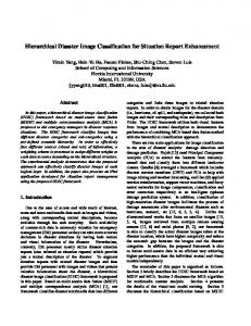
An extensive survey is presented by NASA in [8]. Pullum [9] has categorized the software fault-tolerant techniques into data and design diversity approaches. Hanmer [10] has introduced patterns for fault-tolerant software, e.g. architectural, detection, error recovery, mitigation, and treatment patterns. About twenty various dependability-oriented hardware and software fault-tolerant designs are presented in the aforementioned literature. The authors proposed different classifications and evaluated relevant properties. However, they emphasize particular implementations and ignore the internal conceptual structural similarities of the introduced designs. Contribution of this paper: In contrast, we extract the fundamental, implementation-independent patterns and demonstrate that the mentioned fault-tolerant designs are particular implementations of them. The overview of the defined design patterns is shown in Figure 1. Three basic and four combined design patterns are presented in this paper, along with simple reliability evaluation examples. Common hardware and software implementations of each design pattern are listed. This paper does not propose any new particular technique to achieve fault tolerance, however, it proposes a new classification that organizes the existing techniques into a structured pattern system, with a unified representation. The presented dependability-oriented design patterns can be applied to different hierarchical software, hardware, and system levels in order to increase overall dependability. The introduced classification gives a systematic overview, supports the choice of an appropriate mechanism, and provides a guidance for the building of fault-tolerant systems. III. BASIC DESIGN PATTERNS This section introduces three basic design patterns: comparison, voting, and sparing. A. Comparison pattern The first basic design pattern is termed comparison (C). The concept behind the comparison pattern is that a fault can be detected if two components’ results disagree. Two components perform the same computation in parallel and their results are compared by a comparator, shown in Figure 2a. If a fault is detected, an error signal is generated either to shut down the entire system or to switch the system into a fail-safe state. This pattern can only detect faults. It does not contain any error correction means. It is not possible to determine which component is faulty if the results of two components disagree. Therefore, this pattern is usually combined with other patterns. Reliability evaluation example: Assuming that the comparator is perfect and the reliability of a component equals R, the reliability of the system that follows this pattern is RC = R2 . The equation shows that the reliability declines after the application of this pattern, because R2 < R for
Basic design patterns Cmp
agree/ disagree
input
Component 2
input
Error detection
Spare 1 Error detection
Component N
Spare N-1
C+V
S
V+C
C+S
Component 1
Cmp
Component 2
Cmp
Component 1
Cmp
. . .
Component 2
Voter
output input
Voter
output
input
Cmp
Component N
Cmp N to 1 output switch
. . .
Component N-1
. . .
Component N-1
output N to 1 switch
Error detection
V
Component 1
Component N
output
. . .
C
Component 2
Voter
. . .
Component 2
input
Component 1
Component 1
output
Component 1 input
Component N
Cmp
Cmp
V+C+S Component 1
Cmp
. . .
Component N
Cmp
Spare 1
Cmp
input
N out of (N+K) switch
. . .
Voter
output
. . .
Combined design patterns
Spare K
Cmp
Figure 1: The proposed classification of fault-tolerant design patterns. Three basic design patterns (top) can form various combinations. The four combined design patterns (bottom) are presented.
0 < R < 1. However the safety increases, since the system will be switched to a fail-safe state after the error detection. B. Voting pattern The second basic design pattern is termed voting (V). The components are replicated to perform the same operation in parallel. The N produced results are compared by a majority-voting system (a voter) in order to determine the correct result (Figure 2b). The system functions correctly as long as the majority of components are fault-free. This pattern masks (N − 1)/2 faults. In order to make majority voting possible, N is selected to be odd. In the basic case, N is selected to three, then a fault of one component can be masked. In case of hardware triple modular redundancy (TMR), the voter can mask the fault of one hardware module. This pattern prevents a single component’s failure from causing a failure of a complete system. The N homogeneous or heterogeneous components can be used. The system with homogeneous components can tolerate only random faults. Whereas the system with heterogeneous, but functionally equivalent, components can deal with both random and systematic faults. One drawback of this pattern is that the voting does not identify the type or the reason of a fault. Also, the voter could be a single-point of failure. However, this problem can be solved either by using multiple replicated voters [11] or a simple and highly reliable voter. Reliability evaluation example: Under the assumption that the reliabilities of all components are equal to R, the components are mutually independent, and the voter is perfect, the reliability of the system that exploits this design
output
Component 1 input
Cmp
agree/ disagree
Component 2
(a) Comparison pattern: The outputs of two components are compared by a comparator in order to detect an error. Component 1 input
Component 2
Voter
output
. . .
Component N
(b) Voting pattern: The outputs of N components are processed by a majority voter that can mask (N − 1)/2 faults.
IV. C OMBINED DESIGN PATTERNS
Component 1 input
Error detection
Spare 1 . . .
are applied that allows a spare program to load the last saved state and take over the execution [8]. Several different software implementations follow the sparing pattern. Checkpoint and restart: restart the same program on the same processor. Process pairs: restart the same program on another processor. Recovery block: restart a diverse version of the program on the same processor. Distributed recovery block: concurrently execute diverse versions of the program on different processors. N self-checking programming using acceptance tests: concurrently execute diverse versions with additional ATs on different processors. Reliability evaluation example: Under the assumption that all components are independent, have equal reliabilities and the error detection units are ideal, the system’s reliability is RS = 1 − (1 − R)N .
Error detection
N to 1 switch
output
Spare N-1 Error detection
(c) Sparing pattern: The faulty active component is replaced by a spare one after an error is detected.
Figure 2: Basic design patterns. � � N X N Ri (1 − R)N −i pattern can be estimated: RV = i N +1 i=
2
C. Sparing pattern The sparing (S) pattern: If a fault is detected by a builtin error detection unit in an active component, a spare component takes over. This enables a system to continue its correct operation. The basic configuration of the sparing pattern is illustrated in Figure 2c. Only one component is operational and the remaining N − 1 components serve as spares. There are three types of standby sparing: hot, warm and cold. Hot: the spares are performing the computation, ready to take over the operation at any time. Warm: the spares are initialized, and stay idle. Cold: the spares are powered up only when they are needed. Ideally, this pattern can tolerate N − 1 faults. However, not all the faults can be detected by the error detection unit. Koren [12] has defined the coverage factor c as the probability of successful detection that the faulty active component is correctly diagnosed, identified and disconnected. In hardware, an error detection unit identifies faults, e.g. by range check or state check. In software, various techniques of acceptance tests (AT) are used, e.g. timing, coding, reversal, reasonableness, and structural checks [4], [13]. Furthermore, static and dynamic checkpoint techniques
The three basic design patterns can be combined in order to improve the dependability even further. This section introduces four combined design patterns. Each of the combined design patterns is a conjunction of the basic patterns. Other possible hierarchical combinations can be built and evaluated in a similar way. A. Comparison then sparing pattern In the comparison then sparing (C+S) pattern, all the components are grouped in pairs. The first pair is on-line and its outputs are compared to detect a mismatch. If the results disagree, another pair takes over (Figure 3a). The system is operational until one of the components in the last pair fails. Reliability evaluation example: The reliability of this pattern is RCS = 1 − (1 − R2 )N/2 . For instance, a system with two pairs produces a correct output either if i) both components in the first pair work correctly or ii) the first pair generates a disagreement, but the second pair takes over and operates correctly. B. Comparison then voting pattern In this comparison then voting (C+V) pattern (Figure 3b), N components are grouped into N/2 pairs that are operating concurrently. All the pairs form a voting system in order to mask faults. In each pair, the outputs of two components are compared for the fault detection. If the outputs agree, the result is submitted to the voter. Otherwise, the pair is removed from the system. Reliability evaluation example: The reliability of a pair equals R2 . In other words, the failure probability of a pair is 1 − R2 . This pattern can operate even if only one pair is left and functions correctly. Accordingly, the reliability of the system is RCV = 1 − (1 − R2 )N/2 . The reliability of the comparison then voting pattern is equal to the reliability of the comparison then sparing pattern, because both can provide reliability until the last pair is
Component 1
Cmp
Component 2
input
N to 1 output switch
. . .
Component N-1
Cmp
Component N
(a) Comparison then sparing pattern. Component 1
Component 2
input
D. Voting, comparison then sparing pattern Cmp
. . .
Voter
output
Component N-1
Component N
Cmp
(b) Comparison then voting pattern.
input
Component 1
Cmp
Component 2
Cmp
Voter
output
. . .
Component N
Cmp
(c) Voting then comparison pattern.
Component 1
V. C OMPARISON OF RELIABILITY PROPERTIES Cmp
input Spare 1
Cmp
N out of (N+K) switch
. . .
Voter
output
. . .
Spare K
The structure of the voting, comparison then sparing (V+C+S) pattern is shown in Figure 3d. Basically, it extends the V+C pattern, described in the previous section, with a switch that replaces a faulty component with a spare one. This pattern guarantees high dependability as long as the spare pool is not exhausted. This pattern improves the fault masking capability of the basic voting pattern. For instance, three components with one spare can mask 2 faults, while a basic voting pattern would need 5 components. Reliability evaluation example: Following the logic of the V+C pattern, the V+C+S pattern tolerates N + K − 2 faults: RV CS = 1−(1−R)N +K −(N +K)R(1−R)N +K−1 , where N is the number of components, and K is the number of spares. According to the simplified reliability evaluation, the efficiency of the V+C+S and V+C patterns is the same for the same total number of components. However, in case of V+C+S, fewer components are on-line at the same time. This reduces power consumption and the load on the voter. Also, the off-line components do not wear out.
Cmp
. . .
Component N
ally, the outputs of these components are compared with the output of the voter. In case of disagreement, a comparator disconnects the faulty component from the voting system. Reliability evaluation example: This pattern can tolerate N − 2 faults and disconnect faulty components. After N − 2 components are removed, the voter can not determine which of the rest two components is faulty if they provide different outputs. In other words, the system is unreliable if N − 1 or all N components have failed. The reliability of this design pattern is RV C = 1 − (1 − R)N − N R(1 − R)N −1 .
Cmp
(d) Voting, comparison then sparing pattern.
Figure 3: Combined design patterns.
left. However, this stands only under the assumption that the comparators are perfect. Otherwise, the reliability of the C+V pattern is higher because of the additional fault masking capability of the voter. Triple duplex is a common hardware implementation of this pattern. Software designs that follow the C+V pattern are not popular, since at least six diverse versions are required, which is rather costly. C. Voting then comparison pattern The voting then comparison (V+C) pattern is shown in Figure 3c. N components form a voting system. Addition-
Figure 4 compares the reliabilities of the introduced design patterns under the common simple assumptions that all components are independent and their reliabilities are equal. Voters, comparators, and switches are considered to be perfect. The number of components N is selected individually for each pattern. For example, we compare the voting (V) pattern with 3 and 5 components. The comparison then sparing (C+S) and comparison then voting (C+V) patterns are grouped together, since they have the same reliability. The dashed line (None) represents the system of a single component without any redundancy. The reliability of the comparison (C) pattern is the lowest one. It is even lower than the reliability of the nonredundancy system (None). However, this pattern allows error detection that increases safety. Therefore, it is typically used in combination with other basic patterns. The voting pattern is only reasonable if the reliability of a component is higher than 0.5. The simple structure of the voting pattern makes it an effective practical solution. Obviously, the reliabilities of the combined patterns C+S, C+V, V+C, and V+C+S are higher than the reliabilities of the basic
Figure 4: Comparison of the reliabilities of the introduced design patterns.
patterns. The C+S and C+V patterns with 6 components are reasonable when the component reliability is higher than 0.389. The V+C can be applied even with very unreliable components that have the reliability of 0.131 or higher. The V+C+S pattern shows the best result because of additional spares. The sparing (S) pattern is an exceptional case since it can not be used without additional error detection units. The S curve in Figure 4 shows the case of ideal error detection mechanisms that practically can not be easily achieved. The discussed trivial approach to the reliability analysis gives a transparent example of the evaluation based on the defined design patterns. The transition to more sophisticated methods that eliminate the above mentioned assumptions and exploit more complex mathematical models like Markov chains or Petri Net is rather straightforward. VI. C OMMON IMPLEMENTATIONS OF DEFINED DESIGN PATTERNS
The common hardware and software implementations of the defined fault-tolerant design patterns are briefly discussed in this section, summarized in Table I and II. C: Duplication with comparison [3] is a hardware implementation of the comparison pattern. Two identical hardware modules operate concurrently in order to detect hardware random faults. A component in Figure 2a represents a hardware module. Similarly, two different, but functionally equivalent, hardware modules can be used to detect hardware systematic faults. C: Two-version comparison is a software implementation of the comparison pattern. Two versions of software are implemented and executed in parallel to detect a design fault. A component in Figure 2a represents a software version. V: N-modular redundancy (NMR) [14] is the common hardware fault-tolerant design: N identical hardware modules operate in parallel to mask hardware random faults. A component in Figure 2b represents an identical hardware module. The NMR can only deal with random faults. It does not offer sufficient protection against design faults. Triple Modular Redundancy (TMR) is the basic form of NMR.
V: N-version programming [15] is a software implementation of the voting pattern, based on the design diversity. The concept is the independent development (different groups, algorithms, programming languages, etc) of N functionally equivalent software versions using the same specification. This helps to tolerate software design faults that cannot be tolerated by e.g. triplicating the same version, because all copies will fail identically. N diverse software versions are executed in parallel, usually on different hardware devices. However, the implementation of N versions is costly and it is also difficult to reach a consensus in their outputs even if all versions are correct [12]. A component in Figure 2b represents a diverse software version. V: N-copy programming [16] is a software implementation of the voting pattern. It is based on data diversity technique and uses N copies of a single program, executed on N processors, see Figure 5a. However, the system’s inputs are run through a data re-expression unit and each copy receives a diverse input. There are three basic data diversity approaches [8], [9], [16]: input data re-expression, input re-expression with post-execution adjustment, and reexpression via decomposition and recombination. A component in Figure 2b represents a data re-expression unit and a copy of the program. Although the same version is used, the components are still heterogeneous due to the diversity of the re-expression units. The problem of this design is that not all software programs can accept input data re-expression. V: Acceptance voting [17] applies acceptance tests to the N-version programming in order to enhance the fault detection capability. Not only N versions of a program, but also N corresponding ATs are used (Figure 5b). Only the result, which passes the AT are sent to a dynamic voter that can adapt to the decreasing number of the inputs. A component in Figure 2b represents a version and an AT. In a similar manner, the hardware NMR can be extended with error detection mechanisms. S: Standby sparing [18] is a hardware implementation of the sparing pattern. In the basic case, two homogeneous or heterogeneous modules are used. The homogeneous duplex is a form of standby sparing, which uses two identical modules to deal with hardware random faults. While heterogeneous duplex consists of two independent different modules to handle hardware random and systematic faults. S: Checkpoint and restart [19] is a software implementation of the sparing pattern. The basic configuration is shown in the block of Figure 6a. Most of the software faults are input sequence and state dependent. Therefore, a simple software restart is usually enough to deal with this fault. If a fault occurs, the software receives a retry signal and starts its backward error recovery, returning to the last stored state. The effectiveness of the checkpoint and restart can be increased by using different input re-expression approaches on each retry (Figure 6a). This design has no obvious spare unit, but it restarts itself after a fault is detected. Therefore,
Table I: Basic design patterns and their common implementations. Pattern Comparison (C)
Voting (V)
Sparing (S)
Implementations Duplication with comparison (HW) Two-version comparison (SW) N-modular redundancy (HW) N-version programming (SW) N-copy programming (SW) Acceptance voting (SW) Standby sparing (HW) Checkpoint and restart (SW) Process pairs (SW) Recovery block (SW) Distributed recovery block (SW) N self-checking programming using ATs (SW)
Brief descriptions Components: two identical hardware modules. Components: two diverse software versions. Components: N identical hardware modules. Components: N diverse software versions. Components: N data re-expressions + N copies. Components: N diverse software versions + N ATs. Spare: an identical hardware module. Spare: the program itself (self-sparing). Spare: same version program on another processor. Spare: a diverse version on the same processor. Spare: a diverse version on another processor. Spare: a diverse version on another processor with AT.
Table II: Combined design patterns and their common implementations. Pattern
Comparison then voting (C+V) Voting then comparison (V+C)
Implementations Pair-and-a-spare (HW) N self-checking using comparison (SW) Triple duplex (HW) Self-purging (HW)
Voting, comparison then sparing (V+C+S)
NMR with spares (HW)
Comparison then sparing (C+S)
input
Data re-expression 1
Copy 1
Data re-expression 2
Copy 2
Voter
output
. . . Data re-expression N
Copy N
(a) N-copy programming.
input
Version 1
Acceptance test 1
Version 2
Acceptance test 2
Voter
output
. . .
Version N
Acceptance test N
(b) Acceptance voting.
Figure 5: Software implementations of the voting pattern.
it is considered to be a “self-spare”. S: Process pairs [20] is a software implementation of the sparing pattern, which restarts the same software version on another processor after a fault is detected (Figure 6b). A hardware redundancy is required, i.e. an extra processor, thus this design provides also hardware fault tolerance. The Processor 1 (primary) executes the program and sends checkpoints to the Processor 2 (secondary). If the result failed to pass the AT, the primary processor is switched off, and the secondary processor loads the last checkpoint and takes over the execution. The data re-expression techniques are also compatible with the process pairs. S: Recovery block [21], [22] is another software imple-
Brief descriptions C: two identical hardware modules, S: another pair. C: two diverse software versions, S: another pair. C: two identical hardware modules, V: N pairs. V: N hardware modules, C: voted and individual results. V: N hardware modules, C: voted and individual results, S: one hardware module.
mentation of the sparing pattern, which applies the checkpoint and restart technique to multiple versions of software in order to handle software systematic faults. In the presence of a software fault, a different version software is restarted on the same processor unit (Figure 6c). Recovery block is a kind of cold standby scheme, based on fault detection with ATs and backward recovery. At the beginning, the primary version is active and its output is submitted to the AT. If the AT fails, a retry signal is sent to the switch, the system is rolled back to the last state that is stored in the checkpoint memory, then an alternative version takes over. If all alternatives are unsuccessful, the system fails and a failure is reported. The success of the recovery block approach strongly depends on the quality of the AT. S: Distributed recovery block [23] extends the recovery block with hardware redundancy, thus provides both hardware and software fault tolerance. The primary and alternative software versions are executed concurrently, distributed on N different hardware units (nodes). For simplicity, only two nodes and two versions are shown in Figure 6d. Each node carries both a primary and a secondary software version. Node 1 executes the primary version followed by an AT. At the same time, Node 2 executes the secondary. Compared to the recovery block, the distributed recovery block implements the forward recovery approach. If in Node 1 the primary version fails the AT, the output of the alternative version that passes the AT from Node 2 is used, and the roles of the primary and secondary versions are reversed. Since all versions are executed in parallel, this design does not require any checkpoint technique. S: N self-checking programming using acceptance tests [24] is based on the software design diversity and a self-checking technique (Figure 6e). A switch selects the
software version with the highest rank which has passed its AT. Two main differences from the recovery block are: i) not only N software versions but also N corresponding ATs are used; ii) all versions are executed concurrently, in a hot-standby fashion, therefore checkpoints are not required. C+S: Pair-and-a-spare [3] is a hardware implementation of the comparison then sparing pattern, which combines the duplication with comparison and the standby sparing. In Figure 7, two modules are on-line and their results are compared. In addition, error detection units are associated with each module to enhance the fault detection capability. C+S: N self-checking programming using comparison [24] is a software implementation of the comparison then sparing pattern. A component in Figure 3a represents a version of a software program. N versions are executed on N hardware units. Two versions are executed as an active pair, while the other pairs are hot spares. The outputs of the active pair are compared to detect software systematic faults. If a fault is detected then another pair takes over. This design was used e.g. in Airbus A-320 flight control systems. C+V: Triple duplex combines the duplication with comparison and the TMR designs. This design follows the comparison then voting pattern. A component in Figure 3b represents a hardware module. Six identical hardware modules, grouped in three pairs, are operating in parallel. This design is used e.g. in Boeing 777 primary flight computer. V+C: Self-purging [25] is a hardware implementation of the voting then comparison pattern that combines the NMR and the duplication with comparison. The modules form an NMR and are associated with switches. Each individual module’s output is compared with the voted system’s output. In case of disagreement, the switch removes its connected module from the system. The voter is a threshold gate that is capable of adapting to the decreasing number of inputs. V+C+S: N-modular redundancy with spares [26] is the hardware implementation of the voting, comparison then sparing pattern. The system comprises N modules, K spares, a voter, a disagreement detector and a switch, shown in Figure 8. The internal structure of the disagreement detector is similar to the comparators in Figure 3d.
Checkpoint Memory Selection
. . .
output
Program retry
Data re-expression N
Acceptance Test
(a) Checkpoint and restart: restart the same program on the same processor (“self-spare”).
Processor 1 input
Checkpoint
output
Switch
Processor 2
retry
Acceptance test
(b) Process pairs: restart the program on another processor. Checkpoint memory Primary version
input
Alternative version 1 . . . Alternative version N-1
output
Switch
Acceptance test
(c) Recovery block: restart a diverse version of the program on the same processor. input Node 1
Node 2
Primary
Primary
Secondary
Acceptance test
Secondary
Acceptance test
Switch
output
(d) Distributed recovery block: concurrently execute diverse versions of the program on different processors.
VII. C ONCLUSION Comprehensive analysis of common dependabilityoriented hardware and software fault-tolerant designs reveals a number of implementation-independent conceptual similarities that were formalized into several design patterns. Three basic design patterns have been introduced: comparison, voting, and sparing. These three basic patterns can be combined and form more complex and efficient structures. Four combined design patterns have been presented: comparison then sparing, comparison then voting, voting then comparison, and voting, comparison then sparing. The reliabilities of all discussed patterns have been evaluated and compared. The introduced classification of fault-tolerant
Data re-expression 1
input
Version 1 Acceptance test 1
input
output
Version 2 . . .
Acceptance test 2
N to 1 switch
Version N Acceptance test N
(e) N self-checking programming using acceptance tests: concurrently execute diverse versions with additional acceptance tests on different processors.
Figure 6: Software implementations of the sparing pattern.
Module 1 Error detection
input
output
Module 2
N to 2 switch
Error detection
. . .
Cmp agree/ disagree
Module N Error detection
. . .
[14] J. Von Neumann, “Probabilistic logics and the synthesis of reliable organisms from unreliable components,” Automata studies, vol. 34, pp. 43–98, 1956.
Module 1 . . .
N Modules
N out of (N+K) switch
Module N Spare 1 . . .
[12] I. Koren and C. M. Krishna, Fault-tolerant systems. Morgan Kaufmann, 2010. [13] P. A. Lee and T. Anderson, Fault tolerance: principles and practice. Springer Science & Business Media, 2012, vol. 3.
Disagreement detector
input
[10] R. Hanmer, Patterns for fault tolerant software. John Wiley & Sons, 2013. [11] M. L. Shooman, Reliability of Computer Systems and Networks: Fault Tolerance,Analysis,and Design. New York, NY, USA: John Wiley & Sons, Inc., 2002.
Figure 7: Hardware implementation of the comparison then sparing pattern: Pair-and-a-spare with error detection units.
. . .
[9] L. L. Pullum, Software fault tolerance techniques and implementation. Artech House, 2001.
. . .
Voter
output
K Spares
[15] A. Avizienis and L. Chen, “On the implementation of nversion programming for software fault tolerance during execution,” in Proc. IEEE COMPSAC, vol. 77, 1977, pp. 149– 155.
Spare K
Figure 8: Hardware implementation of the voting, comparison, then sparing pattern: NMR with spares.
[16] P. E. Ammann and J. C. Knight, “Data diversity: An approach to software fault tolerance,” IEEE Transactions on Computers, vol. 37, no. 4, pp. 418–425, 1988. [17] A. Athavale, Performance evaluation of hybrid voting schemes, 1990.
design patterns provides a guidance for the building of dependable systems.
[18] J. Losq, “Influence of fault-detection and switchinig mechanisms on the reliability of stand-by systems,” 1975.
ACKNOWLEDGMENT
[19] K. M. Chandy, J. C. Browne, C. W. Dissly, and W. R. Uhrig, “Analytic models for rollback and recovery strategies in data base systems,” IEEE Transactions on Software Engineering, no. 1, pp. 100–110, 1975.
This work is supported by the German Research Foundation (DFG) project JA 1559/5-1. R EFERENCES [1] J.-C. Laprie, “Dependability: Basic concepts and terminology,” in Dependability: Basic Concepts and Terminology. Springer, 1992, pp. 3–245. [2] C. Alexander, A pattern language: towns, buildings, construction. Oxford University Press, 1977. [3] B. W. Johnson, Design & analysis of fault tolerant digital systems. Addison-Wesley Longman Publishing Co., Inc., 1988. [4] E. Dubrova, Fault-tolerant design.
Springer, 2013.
[5] B. P. Douglass, Real-time design patterns: robust scalable architecture for real-time systems. Addison-Wesley Professional, 2003, vol. 1. [6] A. Armoush, “Design patterns for safety-critical embedded systems.” Ph.D. dissertation, RWTH Aachen University, 2010. [7] M. R. Lyu et al., “Handbook of software reliability engineering,” 1996. [8] W. Torres-Pomales, “Software fault tolerance: A tutorial,” 2000.
[20] C. Dimmer, “The tandem non-stop system,” in Resilient computing systems: vol. 1. John Wiley & Sons, Inc., 1986, pp. 178–196. [21] J. J. Horning, H. C. Lauer, P. M. Melliar-Smith, and B. Randell, “A program structure for error detection and recovery,” in Operating Systems. Springer, 1974, pp. 171–187. [22] B. Randell, “System structure for software fault tolerance,” in ACM SIGPLAN Notices, vol. 10, no. 6. ACM, 1975, pp. 437–449. [23] K. Kim and H. O. Welch, “Distributed execution of recovery blocks: An approach for uniform treatment of hardware and software faults in real-time applications,” IEEE transactions on Computers, vol. 38, no. 5, pp. 626–636, 1989. [24] J.-C. Laprie, J. Arlat, C. Beounes, and K. Kanoun, “Definition and analysis of hardware-and software-fault-tolerant architectures,” Computer, vol. 23, no. 7, pp. 39–51, 1990. [25] J. Losq, “A highly efficient redundancy scheme: self-purging redundancy,” IEEE Transactions on Computers, vol. 100, no. 6, pp. 569–578, 1976. [26] D. P. Siewiorek and E. J. McCLUSKEY, “An iterative cell switch design for hybrid redundancy,” IEEE Transactions on Computers, vol. 100, no. 3, pp. 290–297, 1973.