Engineering Letters, 23:3, EL_23_3_07 ______________________________________________________________________________________
Close-Range Photogrammetry Approach for the Virtual Prototyping of an Automotive Magnetorheological Semi-active Differential F. Renno, M. Terzo
Abstract— First target of this paper is to describe the design of an automotive semi-active differential based on the use of a Magnetorheological Fluid (MRF). The MRF allows to control the locking torque and, consequently, to improve the vehicle handling. Second target is to propose a method grounded on a Close-Range Photogrammetry approach for the CAD modeling phase of the device ideated, alternative to the use of the typical Reverse Engineering (RE) techniques. In fact, although a Reverse Engineering process allows the complete 3D reconstruction of the external surfaces and features of a real object, it could often take a lot of time and, in some cases, could be affected by some approximations or errors. Furthermore, a model “reconstructed” could not be the best solution for multiphysics analyses, where the parametric geometry is needed for the modifications of all its features and dimensions for the optimization process in a very short time. For these reasons, in the case studied, the complete CAD prototype, created step by step, is needed and the photogrammetry can represent an interesting solution to enhance the virtual prototyping phase without repercussions on the quality of the results. Starting from the acquisition of particular “key points”, with an acceptable tolerance, the definition of the references (datum axes, curves, planes, centres of holes) needed for the CAD modeling, according to the Top-Down procedure, was possible. Once obtained the preliminary prototype, the final CAD model was created optimizing its dimensions and choosing the adequate materials. To evaluate the goodness of the procedure adopted, the MRF LSD geometry was reconstructed also by means of the Reverse Engineering techniques applied to the physical prototype of the new device ad hoc created. In particular, laser system acquisition and RE dedicated software were used. In this way the comparison between the photogrammetric and Reverse Engineering procedures (in terms of time spent and quality of the results) was allowed and so conducted. Lastly, the results of the FEM analyses carried out to validate the design process and the methodology ideated and adopted were showed. Index Terms—Photogrammetry, Magnetorheological Fluid, Reverse Engineering, Automotive Differential, 3D CAD parametric modeling, Direct Modeling, FEM Analysis.
T
I. INTRODUCTION HE Digital Mock-Up (DMU) of a real object can be created by means of the Virtual Prototyping techniques.
F. Renno is with the Dipartimento di Ingegneria Industriale, Università degli Studi di Napoli Federico II, Napoli, 80125 ITALY (e-mail:
[email protected]). M. Terzo is with the Dipartimento di Ingegneria Industriale, Università degli Studi di Napoli Federico II, Napoli, 80125 ITALY, (corresponding author, phone: +390817683277; fax: +390812394165; e-mail:
[email protected]).
They allow to perform detailed analyses and simulations of the behaviour of the final prototype before its manufacturing and to predict its good performances and possible weaknesses. So the costs and the time to market of the new products can be reduced and the quality of the results can be improved. Computer Aided Design (CAD), Computational Fluid Dynamics (CFD), Virtual Reality (VR), Augmented Reality (AR), Digital Human Modeling (DHM) and Virtual Manufacturing (VM) are included among the VP techniques [1, 2]. By now, also the Reverse Engineering (RE) can be considered part of it and is really common. It allows to get the digital duplication of a real object starting from a point cloud acquired by means of contact or contactless systems. The result of this process can be used in virtual environment to clone the object, to measure or also to modify it. Then, if a 3D printer is available, the manufacturing of the real model is easily achievable. Therefore, the Reverse Engineering techniques are strictly integrated into the production process and they are deeply used in many fields like: industrial (automotive, aerospace, manufacturing), computer graphics (simulations, videogames), archaeological and biomedical [3, 4]. The Photogrammetry can be included among the techniques usable for the 3D measurements and acquisitions. It is a passive image-based and very portable method that uses projective geometry to produce 3D point measurements by taking photographs from at least two different positions [5]. Some interesting industrial appliances and tools are available in [6]. For example, Photogrammetry techniques are used by many companies to get a high accurate points acquisition in particular for very large objects measurement. The Steinbichler German company produces 3D measurements based on the use of coded targets which guarantee very accurate results and offer high freedom on digitizing large and complex objects, i.e. 1:1 car model with an overall accuracy of 0.15 mm [7]. The realization of a preliminary CAD model is the first step to get the best opportunities offered by the Virtual Prototyping techniques to improve the design phases. The second step is to detail and submit it to the virtual testing. Then, the powerful FEM methods allow to establish the direct link between the simulated and the physical results and overthrow the wall between the virtual and the real models. The huge number of uses of the VP techniques is remarkable, from educational to computer graphics (videogames and renderings), from industrial to medical
(Advance online publication: 10 July 2015)
Engineering Letters, 23:3, EL_23_3_07 ______________________________________________________________________________________ fields. Referring only to the last years, many interesting case studies related to the automotive industry are available in literature, from the virtual prototyping of an automobile steering system using a haptic feedback [8] to the evaluation of an advanced levelling light system by means of a VR based night drive simulator [9]. Also in the aerospace field, a notable study on the definition and the optimization of the future space missions by means of an immersive visualization environment machine has been proposed [10]. Moreover, simulators are often used to study and predict the human behaviour during the flight in hostile conditions [11]. Besides, the Virtual Prototyping techniques are becoming fundamental in the nuclear fusion field [12 - 16]. In [12, 13] its advantages for the development of the nuclear fusion plants and their devices are showed. The practicability of the assembly operations of all the components of the tokamak (device for the production of the controlled thermonuclear fusion power) combining the CAD modeling with the Virtual Reality techniques is showed in [14]. In particular, the design of a Remote Handling (RH) system is described; during the maintenance operations it allows to move each part to be mounted inside the tokamak along the path to follow. So the simulation of all the movements allows the detection of the possible collisions in real time. In this way, researchers and engineers can obtain the best design results comparing several alternative solutions in an interactive manner during virtual design reviews in virtual reality laboratories. Furthermore, it is possible to study the interactions between electromagnetic (EM) loads and structures [16]. Rheology is the study of flow and deformation of materials under applied forces. Many commonly-used materials show complex rheological properties. In particular, their viscosity and viscoelasticity can vary under different external conditions, such as stress, strain, temperature and magnetic fields. Internal sample variations such as protein concentration and stability, and formulation type for biopharmaceuticals, are also important parameters that determine rheological properties [17]. So, the peculiarity of the change of the behaviour of the Magnetorheological fluids (MRF) varying the properties of the magnetic field applied can be very interesting. For this reason the use of the MRF became very common and remarkable in several application fields. II. TARGETS This paper aims at showing how a Close-Range Photogrammetry process allows to acquire easily only some particular points with a good accuracy and to design and realize the CAD model of an innovative controllable limited slip differential. The main aspect of this new device is the use of a contactless clutch activated by means of the magnetisation of a Magnetorheological (MR) fluid [18, 19]. After the definition of the appropriate architecture, a preliminary virtual prototype was realized. The design of the Magnetorheological Fluid Limited Slip Differential (MRF LSD) started from the constraints imposed by the available space that in origin was occupied by a passive device (free differential) located in the gearbox of a common Front Wheel Drive (FWD) vehicle. One of the main facets analysed in this paper is the
usability of the Photogrammetry instead of a Reverse Engineering approach. Several studies about the use of RE techniques for the 3D reconstruction of automotive components are available in literature [20-21]. In particular, in a previous publication [18], the authors described the RE procedures adopted to acquire and reconstruct, by means of a laser system and a RE-dedicated software, the 3D model of the gearbox where the device to design has to be installed. But, aim of this paper is to examine the advantages and the convenience of an alternative approach based on the photogrammetry. In fact, the complete 3D reconstruction of the surfaces and the successive feature recognition phase, by means of the typical RE procedures and tools, could be often a long time process and sometimes the results could not satisfy the project requirements. Furthermore, some features (i.e. hollows and cavity, especially with laser system acquisitions) could be too much approximated, worsening the final result. Moreover, in some cases, the detailed CAD model might be needed and the results of the RE process could not be sufficient to modify the final prototype reconstructed easily. On the contrary, that is possible if the parametric CAD model is available. So, the main target of this work is to show how, starting from a Close-Range Photogrammetry process, the acquisition of only some particular points, with a good accuracy can be easy. It allows to define the position of the foremost datum planes, axes and of the specific features to be used during the CAD modeling phase with a Top-Down approach. Moreover, no expensive hardware devices (like Laser scanner or CMM) are needed. A Digital Single-Lens Reflex Camera and a photogrammetry software are sufficient and adequate. Then, only the time to acquire and define the needed points in the CAD environment has to be taken into account. So, three main targets are researched and described: --To define the design constraints for the use of the device in a front wheel drive vehicle, acquiring some specific “key” points for the CAD modeling phase by means of the Photogrammetry techniques; --To design and to realize the parametric CAD model of an innovative semi-active device that transfers and biases the torque between the two half-shafts by means of the magnetisation of a magnetorheological (MR) fluid; --To compare the results obtained by means of the photogrammetry and of the Reverse Engineering approaches (in terms of quality and rapidity of the process). The section 3 of the paper analyses the MRF LSD, section 4 describes the virtual prototyping phases followed by means of both the Reverse Engineering techniques and the close-range photogrammetry approaches, whereas the results of the comparison are showed in section 5. Lastly the comparison between the procedures to optimize the results of the FEM analyses based on the “parametric” and “nonparametric” methods is described.
(Advance online publication: 10 July 2015)
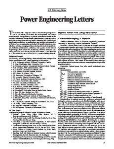
Engineering Letters, 23:3, EL_23_3_07 ______________________________________________________________________________________ III. MAGNETORHEOLOGICAL FLUID LIMITED SLIP DIFFERENTIAL A. Description The need to transmit the torque to the driving wheels and, at the same time, the demand of making the wheels free to rotate at different speed, make the differential very functional for the purpose. The differential (called free or open differential) commonly used receives the torque from the gearbox and splits it into two equal parts that act on the driving wheels. If one of the driving wheel travels on a low friction surface, the tyre-road interaction force is minimized and a limited torque is transmitted to the other one, so the vehicle is unable to start. Suitable passive devices [22] (so called limited slip differentials) were realized in order to transmit the torque to a wheel even if the other one is on a slippery surface. In the limited slip differentials, the two side gears are mated: this locking effect makes the vehicle capable to move also in presence of a wheel characterized by low traction. The locking torque that characterizes the limited slip differentials is typically depending on the wheel relative speed or on the torque acting on the differential case and generates its effects independently from the vehicle handling, e.g. understeering/oversteering. Consequently, in some dynamic conditions, the locking torque can also determine an undesired behaviour of the vehicle [23]. Thanks to the development of the electronic control, semiactive and active differentials were realized: these devices are characterized by a controllable locking torque and typically use hydraulic or electrical actuation systems to engage a clutch which determines issues in terms of wear and NVH (Noise, Vibration and Harshness) due to the sliding between the parts that are in contact. Fig. 1 illustrates the MRF LSD logical scheme. It consists of a semi-active differential constituted by a conventional part and an unconventional one. The side gears (A and B), the planetary gears (G), the differential case (P) and the differential gear (R) characterize the conventional part of the MRF LSD. The unconventional part consists of a disk housing (C) and a coil (S). The disk housing engages the side gear A and the differential case P, and contains facing plates, alternately integral with the side gear and the differential case P, that perform the friction surfaces. Suitable spacer elements create a gap in which the MR fluid is contained. MR fluids are suspensions of micron-sized and magnetisable particles in a carrier fluid. Normally, MR fluids are free-flowing liquids, having a consistency similar to that of a lubricant oil. However, when a magnetic field is applied, their rheology turns into a more solid-like gel. When the magnetic field intensity rises, the ferromagnetic particles find an orientation and the yield stress increases. This property makes the MR fluids functional for the employment in controllable devices [23 ̶ 26].
Fig. 1. Logical scheme of the MRF LSD.
IV. DESIGN AND CAD MODELING OF THE MRF-LSD BY MEANS OF THE PHOTOGRAMMETRY APPROACH A. Configuration Firstly, the layout of the device was defined. The main elements of the MRF LSD are: the Differential case, the Disk housing, the Side and Planetary gears and the Differential Gear. Each part has to be opportunely placed to respect the dimensional requirements and to optimize the magnetic flow to improve the performances of the device. Fig. 2 shows the layout chosen due to the available volume and able to allow to use the disks with the biggest diameter possible to reduce the current needed. The design of the MRF LSD started from a concept generated considering the internal dimensions of the gearbox of a common front wheel drive vehicle equipped with a free differential that followed the scheme illustrated in Fig. 2.
Fig. 2. Layout chosen for the design of the MRF LSD according to the internal volume of the gearbox considered in the case studied.
B. Guidelines for the design of the MRF LSD Since the starting design phases it is possible to optimize the final prototype by means of the CAE techniques. To improve the performances of the device ideated, and also to reduce the design errors, particular interest had to be focused on the analysis of the behaviour and the modification of the magnetic field generated during the functioning. Hence, the CAD model of the MRF LSD was
(Advance online publication: 10 July 2015)
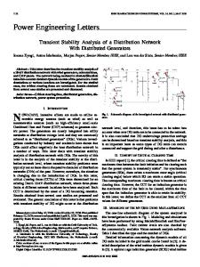
Engineering Letters, 23:3, EL_23_3_07 ______________________________________________________________________________________ needed to change in real time its dimensional and geometric parameters. It is important to note that for the realization of the successive analyses (FEM and multiphysics in particular) is better to have the complete parametric CAD prototype instead of a reconstructed one, i.e. by means of the Reverse Engineering. In fact, the modification of a non-parametric model could often not be easy and a preliminary feature recognition should be performed. Besides, it could be a long time process and the results could be affected by errors. On the contrary, the possibility to easily change the parameters of the CAD prototype allows its optimization in a very short time, without intermediate phases related to the modification of the reconstructed (not parametric) geometry. By now, in fact, the FEM software can communicate with the kernel of the most common CAD software using their powerful tools in real time. The MRF LSD was designed starting from the gearbox of a common front wheel drive vehicle equipped with a free differential. The first step was to conceive the starting concept of the MRF LSD according to the working principle required. Then, the shape and the dimensions of the gearbox were considered and used as constraints to realize the preliminary CAD model of the device. All the CAD parts were created starting from it. At the end of this phase, as a wrong choice could worsen the magnetic efficiency, the materials were opportunely selected and applied to the preliminary CAD model for the successive simulations to define the properties of the magnetic field and to have the full control of the behaviour of the device. So, after this step it was possible to determine the optimal dimensions for the improvement of the performances of the device. It allowed to get the final CAD model. C. Photogrammetry “Photogrammetry is the science of extracting reliable measurements from two dimensional (2D) images” [27]. It is a non-contact method based on the triangulation to produce 3D point measurements by taking photographs from at least two different positions. By mathematically intersecting converging lines in space, the precise location of the point can be determined [28]. The results can be very accurate, in particular if close-range and very close-range methods are used. This technique dates back to 1851 thanks to the French officer Aime Laussedat, who developed the first photogrammetrical devices and procedures. Nowadays, they are used in many fields like: GIS, Map production (Topography), Building CAD Model reconstruction (Civil Engineering), Architectural & Historical Preservation, Automotive, Tooling inspection, Reverse Engineering of parts by aftermarket fabricators (Aerospace engineering), Quality Control, Shipbuilding & Repair [6]. The results of a photogrammetric process can be: a) 3D points coordinates, b) topographical maps, rectified photographs (orthophoto). Photogrammetry techniques can be classified as follows in Fig. 3:
Fig. 3. Classification of the Photogrammetry techniques.
Far-range techniques (areas of m2) are used to produce topographical maps, to reconstruct the shape of buildings, and so on. Close-range and very close-range approaches are suitable for the industrial applications. The dimensions of the physical object and of its features can vary between 1 cm2 and 1 mm2 or smaller areas and a very high accuracy can be obtained [6]. D. Methodology The adopted methodology depended on the use of a digital camera (DSLR, Digital Single-Lens Reflex camera recommended) and of a Photogrammetry-based software (Photomodeler). Four main phases were defined: 1) setting of the process, 2) realization of the photographs, 3) identification of the points and reconstruction of the 3D “point cloud” in the photogrammetry software environment, 4) importing of the results in the 3D CAD software (Siemens NX) for the successive modeling step. During the first phase, the calibration of the camera was very important. It allowed to define the parameters needed for the photogrammetric algorithms i.e. the camera’s focal length, lens distortion, format aspect ratio and principal points. A DSLR camera with a fixed focal length lens was used. The quality of the images, in fact, is an essential requirement to get the best upshots with the photogrammetry technique. The better the photo the better the results. So, the camera was mounted on a tripod to ensure the best sharpness possible and to avoid any movement while the shutter was open that would create an unintentional blur in the photographs. The environment was fairly light and the pictures were taken at least at every 3040 degrees also to avoid occlusions. Moreover, if the object has a complex shape, the risk of occlusions can increase, so the value of the angle can be modified till to 5-10 degrees. CMM systems usually allow to reach the µm accuracy by means of a slow process [4]. Instead, by means of a Photogrammetry-based approach it is quite normal to get errors lower than 1 mm, but special tricks might be adopted to improve this kind of result. Furthermore, the acquisition and the reconstruction processes are very fast. So, a closerange technique may be a suitable solution for a rapid model measurement and/or reconstruction if a very high precision isn’t required. The Photomodeler software, used in the case studied, offers the possibility to get accuracy of the object size till 1:2000 or higher so that for an object with a 10 m longest dimension, and can produce 3D coordinates with 5 mm accuracy at 95%. If other factors are taken into
(Advance online publication: 10 July 2015)
Engineering Letters, 23:3, EL_23_3_07 ______________________________________________________________________________________ account such as good geometry, good camera calibration, it is possible to achieve 1:25.000 or higher accuracy in a project that is all done with particular tricks [4, 28]. In the case studied, the acceptable error was set considering the space available to avoid collisions between the device and the gearbox and the requirements of the device to design. The accuracy of the photogrammetry process ideated (± 0,5 mm max error in each direction) is widely included in this range. E. Close-Range Photogrammetry approach The Top-Down approach was used to realize the CAD model of the MRF LSD, so the definition of the datum planes and axes to use as references was needed [18, 29]. To do this, in this phase, the points to use to create the main datum elements were identified starting from the photographs of the gearbox of the common Front Wheel Drive (FWD) vehicle considered. Then, it was possible to define the related references and features by means of the photogrammetry software used to get it in the CAD environment. The points acquired by means of ten photos taken around the object are showed in Fig. 4. The 1, 2, 3 points were used to define the P0 plane. It is the most important reference. In fact, the main components of the MRF LSD (Differential Case, Differential Gear, Disk Housing) were built by means of revolve features whose sketches were created on it.
Fig. 4. Definition of the points to acquire on the gearbox for the creation of the P0 datum plane (main datum plane).
Furthermore, the 1, 2, 3 and 4 points were used to define two segments (a and b in Fig. 4) used for the identification of the A1 axis that was built by means of their middle points. Then, the P1 plane was defined as perpendicular to the P0 datum through the A1 axis. The P3 and P5 planes, that represent the zone not to be reached to avoid collisions, were realized as offset elements of the P1 plane according to the space available defined by the gearbox dimensions. Similarly, the P2 and P4 datum were obtained starting from the references previously created.
Fig. 5. Datum elements used for the creation of the MRF LSD preliminary CAD model.
All these datum elements defined the structure of the references to use in the CAD environment. Starting from it the sketches for the Feature Based Modeling were realized and the preliminary CAD model of the MRF LSD was built (Fig. 5). F. CAD model and prototype manufacturing The detailed and final CAD model was obtained after the definition of the materials and the optimization of the dimensions of the device (Fig. 6) according to the magnetic field requisites. The selection of the material of each part is an important step in the design of the MRF LSD because of the magnetic permeability, i.e. the aptitude of the material to be crossed by the magnetic flux and so to modify the efficiency of the magnetic field. Therefore, specific choices concerned the materials (Table 1) in the manufacturing phase of the MRF LSD. Considering the costs, the permeability and the manufacturability, low carbon steel (AISI 1008) was selected for the components of the magnetic circuit, i.e. the cores and disks (Fig. 8). Instead, for the non-magnetic parts, AISI 304 was chosen. The selection of the controllable MR fluid was realized starting from the analysis of the commercially available products. In particular, the following characteristics were considered: -- High sensitivity of the MR fluid to the applied magnetic field (B-H curve); -- Low hysteretic behaviour; -- Broad operating temperature range; -- No-field viscosity. Considering the previous properties, the MRF – 140CG®, by Lord Corporation, was chosen. Its characteristics are listed in Table 1.
(Advance online publication: 10 July 2015)
Engineering Letters, 23:3, EL_23_3_07 ______________________________________________________________________________________
Table I. MRF Properties of MRF – 140CG®.
Properties
Value/Limits
Base fluid Operating temperature Density range Color Weight percent solids Specific heat at 25 °C Thermal conductivity at 25°C Viscosity at 40°C
Hydrocarbon -40 °C to 130 °C 3.54 to 3.74 g/cm3 Dark gray 85.44% 0.71 J/g°C 0.28 – 1.28 W/m°C 0.28 (± 0.07) Pa s
The final CAD model of the MRF LSD is composed by two main subassemblies: 1) the Planetary Gears Housing, 2) the Magnetorheological Fluid clutch. The first contains the gears and the Differential case. The Magnetorheological Fluid clutch includes the Coil Housing and the Disk housing. In the first, the bobbin used for the magnetisation is located. The second contains the MR fluid and several plates.
Fig. 6. MRF LSD section.
All the components of the MRF LSD assembly and their chosen materials are listed in Table 2. S/No 1 2 3 4 5 6 7 8 9 10 11 12 13 14 15
Table 2. Components of the MRF LSD. Description Material Side gear A Standard steel Side gear B Standard steel Planetary gear Standard steel Differential case P Low carbon steel (AISI 1008) Differential gear Low carbon steel (AISI 1008) Inner disk Low carbon steel (AISI 1008) Outer disk Low carbon steel (AISI 1008) Spacer elements Austenitic stainless steel (AISI 304) Disk shaft Austenitic stainless steel (AISI 304) Disk housing Austenitic stainless steel (AISI 304) Coil outer housing Low carbon steel (AISI 1008) Coil inner housing Austenitic stainless steel (AISI 304) Coil Copper Sealing Steel Sealing Steel
Fig. 7. MRF LSD manufactured prototype inside the Differential Housing.
G. Reverse Engineering approach – Model reconstructed After manufacturing the MRF LSD, the successive step was its virtual 3D reconstruction by means of the Reverse Engineering techniques to carry out the comparison with the Close-Range Photogrammetry procedure. Usually, the main phases of a RE process are: 1) 3D acquisition (digitizing) and editing of the point clouds, 2) polygonal mesh definition (tessellation), 3) curve and surfaces fitting, 4) feature recognition and CAD model reconstruction [4]. The first step was the digitizing phase of all the elements of the device, previously manufactured, done by means of the Konica Minolta VIVID 9i laser scanner. The results of the 3D measurements were dense point clouds edited and optimized by means of Reverse Engineering dedicated software. Secondly, during the tessellation phase, the preliminary polygonal meshes were created to obtain geometries usable in the CAD environment. Then, it was possible to get the optimal NURBS surfaces. For the sake of simplicity, figures 8a and 8b show only the models of the Differential Case and of the Differential Gear reconstructed by means of NURBS surfaces thanks to Raindrop Geomagic Studio (one of the most common RE software). Finally, the feature recognition phase was pursued (Fig. 9). This could be a very complex and long process and the results could be affected by some errors. In particular, in this phase several geometric entities (points, lines, planes, circles, cylinders, etc.) were used in the Geomagic environment to identify and to assign the features to the elements reconstructed by means of the previous Reverse Engineering steps.
The Fig. 7 shows the manufactured model of the MRF LSD inside the Differential Housing. The differential gear was not completely refined because the teeth were not necessary for the testing process.
(Advance online publication: 10 July 2015)
Engineering Letters, 23:3, EL_23_3_07 ______________________________________________________________________________________ Table 3. Time needed for the tasks of the two alternative processes. Operation Setting process Number of Acquisitions/Photos Post-Processing CAD modeling (of all the components) Total time Full Parametric Model
Fig. 8. Reverse Engineering process of the Differential Case and of the Differential Gear.
So, it was possible to define all the holes, the rounds, the fillets and the planes to use in the CAD environment. Therefore, the final models of the elements of the reconstructed MRF LSD characterized by CAD features were obtained (Fig. 9).
Time Reverse Engineering 10 minutes 10 seconds for each acquisition; 10 acquisitions for each component 2 days (Feature recognition)
Photogrammetry 10 minutes 5 seconds for each photo; 10 photo for each component 1 hour (Points “reconstruction”)
1 day
2 days
Less than 4 days
Less than 3 days
No
Yes
Theoretically, after the feature recognition, a massive CAD modeling phase should neither be considered or performed in the RE approach. However, because some errors occurred for several components in the RE software environment, some hours of work in the CAD software were needed to solve it. With respect to the RE process, the most positive aspect of the photogrammetry approach is that it allowed to perform a very fast acquisition of the points needed to define the references to be used in the CAD environment. But at the same time, the complete modeling phase had to be carried out for all the elements of the device. This drawback was balanced by the result, i.e. a parametric CAD model fully usable for multiphysics analyses. As the optimization of a structure by means of a FEM process can often require a considerable adjustment of the geometry, it is very important to have access to the parameters that allow its upgrading. So, when these parameters are available in the MCAD environment, their modification and upgrade can be obtained in real time and very easily too. For instance, the variation of thicknesses or of dimensions of chamfers and rounds can be realized simply acting on the feature tree. On the contrary, a reconstructed model hasn’t any parameters to control the geometry and so its modification is not quickly achievable and a (complex) feature recognition phase becomes necessary.
Fig. 9. Results of the feature recognition phase of the Differential Case (a) and of the Differential Gear (b).
VI. PARAMETRIC VS RECONSTRUCTED MODEL – FEM ANALYSIS
V. CONSIDERATIONS ON TIME SPENT FOR PHOTOGRAMMETRY AND RE APPROACHES
Fig. 10 shows the procedure usually followed to perform FEM analysis on parametric models realized by means of typical Mechanical CAD software (i.e. NX, CREO, CATIA).
The times to prepare the scene and to realize the reconstruction/modeling of all the components of the case studied, spent for the two alternative approaches, are listed in Table 3. The recognition of the main features of the objects was included in the Reverse Engineering process used, so this step was very slow. On the contrary, the photogrammetry approach was very fast and it was used to acquire and define the position of only some points. But the successive CAD modeling of each components of the MRF LSD took an amount of days of work similar to the one taken by the feature recognition process.
Fig. 10. Procedure to follow starting from the parametric model.
(Advance online publication: 10 July 2015)
Engineering Letters, 23:3, EL_23_3_07 ______________________________________________________________________________________ Their FEM internal solver can be used to study the behaviour of the model under the desired load conditions. Furthermore, if the optimization of the results is required, the modification of the geometry and of its features, by means of the typical Geometric Modeling techniques, is very fast, simple and can be automatized too. Fig. 11 shows, instead, the procedure followed in case of non-parametric models preliminarily obtained by means of the RE techniques. After the 3D reconstruction phase, the feature recognition is needed to define geometrical entities and dimensional parameters by means of RE dedicated software. Furthermore, this phase can be very complex and not free from errors.
As an example, the boundary conditions and the FEM analysis results on the three elements simplified model of the MRF LSD including the differential case, the disk housing and the differential gear (Fig. 12), are shown in the figures 13, 14 and 15.
Fig. 12. Three elements simplified model of the MRF LSD including the differential case, the disk housing and the differential gear.
The needed contact constraints between these parts were defined and the differential case was fixed in correspondence of the two holes at the top.
Fig. 11. Procedure starting from the reconstructed model.
Afterwards, it is possible to import, and then to modify, the geometry into the MCAD environment. However, it is important to remark that new tools and methods, based on the direct modeling techniques, are becoming very useful to modify also non-parametric models in MCAD software (i.e. the so called “Synchronous Technology” in Siemens NX) [30]. For instance, it is possible to act directly on the geometry even if no information about the modeling history is available. Similarly, software like PTC CREO Direct and SpaceClaim allow to edit, manipulate and modify the geometry very easily [31, 32]. To test the validity of the procedure ideated, FEM analyses were performed on some models obtained by means of the two approaches in Siemens NX MCAD software (with MSC NASTRAN kernel). Moreover, the modification of the thickness of the disk housing was considered to simulate the needs of a design change. As it could be foreseen, the procedure showed in Fig. 10 was very rapid and allowed to easily optimize the CAD entities in a short time. On the contrary, even if the second procedure (Fig. 11) gave the similar results for the FEM optimization, it took much time due to the feature recognition phase.
Fig. 13. Load conditions and constraints considered in NX environment.
Then, because of the helical teeth gearing, as load condition, the 1000 N force that causes the wanted torque was considered and tangentially applied on the surface created on the base circle of the differential gear and that subtends two of the teeth (Fig. 13). The maximum stress results were significantly lower than the yield limit of the materials considered, according to the Von Mises criterion (Fig. 14). Therefore, the Stress-Life approach was used to evaluate the durability of the MRF LSD simplified model.
(Advance online publication: 10 July 2015)
Engineering Letters, 23:3, EL_23_3_07 ______________________________________________________________________________________ In fact, the time spent for the use of the approach proposed was shorter than the one based on the Reverse Engineering and Feature Recognition processes. The photogrammetry acquisitions were accurate enough for the tolerance defined in the process ideated. Moreover, the result was a full CAD parametric model to be used for the multiphysics analyses. Then, the parametric and the reconstructed models were used to compare the two procedures for the optimization and the validation of the new device by means of the FEM analyses too. In the end, it is possible to affirm that the proposed method showed interesting results especially for the improvement of the CAD modeling and of the design of the new device ideated, either as for the quality of the results or the time spent to get them. Fig. 14. Results of the stress analysis in NX MCAD environment.
So, under the hypothesis of cyclic load, good results were obtained also for the fatigue life (Fig. 15) [33].
ACKNOWLEDGMENT The authors deeply thank the engineers Antonio Aletta, Roberto Conte, Vito Rufrano and Rosario Salemme for their indispensable technical support. REFERENCES [1] [2]
[3] [4] [5]
[6] Fig. 15. Results of the Fatigue analysis in NX MCAD environment.
VII. CONCLUSIONS An automotive magnetorheological semi-active differential was designed starting from a Close-Range Photogrammetry approach on a common gearbox, that was equipped in origin with a free differential, defining the most challenging geometrical constraints of the new device. Photogrammetry allowed to acquire, on the original model of the gearbox, several “key points” to use in the preliminary CAD modeling phase of the MRF LSD during its virtual prototyping. The successive optimization of the dimensions was performed considering the materials and the available volume. In this way, the final CAD model was defined allowing the manufacturing of the MRF LSD physical prototype. Afterwards, a Reverse Engineering process was realized on it to create a benchmark for the photogrammetric procedure used. So, the comparison of the results of the two approaches allowed to determine that for the case studied the acquisition of only some key points to be used in the Top-Down CAD modeling was more appropriated rather than to reconstruct the non-parametric prototype to be submitted to the following feature recognition phase.
[7] [8]
[9] [10]
[11]
[12] [13]
[14]
[15]
J. Cecil, A. Kanchanapiboon, “Virtual engineering approaches in product and process design”, in The International Journal of Advanced Manufacturing Technology, 2007, 31 (9): 846-856. G. Sun, W. Ren, J. Zhang, “Virtual product development for an automotive universal joint”, International Journal of Automotive Technology, Vol. 12, No. 2, pp. 299−305 (2011), DOI 10.1007/s12239−011−0035−7. V. Raja, K.J Fernandes, “Reverse Engineering, An Industrial Perspective”. Springer Series in Advanced Manufacturing. SpringerVerlag London, 2008. A.C. Telea, “Reverse Engineering - Recent Advances and Applications”, Ed. Intech 2012, ISBN 978-953-51-0158-1. F. Remondino, “From Point Cloud to Surface: the Modeling and Visualization Problem”, International Archives of the Photogrammetry, Remote Sensing and Spatial Information Sciences, Vol. XXXIV-5/W10, 2013. T. Luhmann, “Close range photogrammetry for industrial applications”, ISPRS Journal of Photogrammetry and Remote Sensing 65 (2010) 558–569. H. Steinbichler, “Optical 3D – Scanning and Industrial Applications”, in Proc. of XIII ADM - XV INGEGRAF International Conference on Tools and Methods Evolution in Engineering Design, Cassino, 2003. H. Erdelyi, D. Talaba, F. Girbacia, “Virtual prototyping of an automobile steering system using haptic feedback”, Proc. of the 2nd WSEAS International Conference on Sensors, and Signals and Visualization, Imaging and Simulation and Materials, 2009. pp. 2126. ISBN: 978-960-474-135-9. J. Berssenbrügge, S. Kreft, J. Gausemeier, “Virtual Prototyping of an Advanced Leveling Light System Using a Virtual Reality-Based Night Drive Simulator”, J. Comput. Inf. Sci. Eng. 10(2), Jun 08, 2010. E.N. Harris, W. Morgenthaler, “Planning, implementation and optimization of future space missions using an immersive visualization environment (IVE) machine”, Acta Astronautica 55 (2004) 69-78. Crone D., Sanderson P., Naikar N., “Studying Complex HumanSystem Behaviour: Human-in-the-loop Simulation Requirements”, Proceedings of the Human Factors and Ergonomics Society Annual Meeting, October, 2007, vol. 51 no. 26 1603-1607. A. Raneda, P. Pessi, M. Siuko, H. Handroos, J. Palmer, M. Vilenius, “Utilization of virtual prototyping in development of CMM”, Fusion Engineering and Design 69 (2003) 183-186. G. Di Gironimo, C. Labate, F. Renno, M. Siuko, A. Lanzotti, F. Crisanti, An interactive design approach for nuclear fusion purposes: remote handling system for FAST divertor, Int J Interact Des Manuf, Volume 8, Issue 1, February 2014, Pages 55-65. G. Di Gironimo, C. Labate, F. Renno, G. Brolatti, F. Crescenzi, F. Crisanti, A. Lanzotti, F. Lucca, “Concept Design of Divertor Remote Handling System for the FAST Machine”, International Journal on Interactive Design and Manufacturing 3 (2), pp. 65-79, 2013. Di Gironimo, G., Carfora, D., Esposito, G., Labate, C., Mozzillo, R., Renno, F., Lanzotti, A., Siuko, M., “Improving concept design of
(Advance online publication: 10 July 2015)
Engineering Letters, 23:3, EL_23_3_07 ______________________________________________________________________________________
[16]
[17]
[18] [19]
[20] [21] [22] [23]
[24]
[25]
[26]
[27] [28] [29]
[30] [31] [32] [33]
divertor support system for FAST tokamak using TRIZ theory and AHP approach”, Fusion Engineering and Design 88 (11) , pp. 30143020, 2013. Ramogida G., Calabrò G., Cocilovo V., Crescenzi F., Crisanti F., Cucchiaro A., Di Gironimo G., Fresa R., Fusco V., Martin P., Mastrostefano S., Mozzillo R., Nuzzolese F., Renno F., Rita C., Villone F., Vlad G., “Active toroidal field ripple compensation and MHD feedback control coils in FAST”, Fusion Engineering and Design 88 (6-8) , pp. 1156-1160, 2013. R. Durairaj, L.W. Man, L.J. Ping, L.S. Pheng, and R.T. Subramaniam, “Rheology and Processability of Diglycidylether of bisphenol-A (DGEBA) and Polyurethane (PU) based Isotropic Conductive Adhesives Filled with Different Size-distributed Silver Flakes and Silver Particles”, Engineering Letters, vol. 21, no. 3, pp.143-148, 2013. A. Lanzotti, F. Renno, M. Russo, R. Russo, M. Terzo, “Design and development of an automotive magnetorheological semi-active differential”, Mechatronics, vol. 24, no. 5, pp. 426 – 435, 2014. A. Lanzotti, F. Renno, M. Russo, R. Russo, M. Terzo, “A physical prototype of an automotive magnetorheological differential”, Lecture Notes in Engineering and Computer Science: Proceedings of the World Congress on Engineering 2013, WCE 2013, 3-5 July, 2013, London, U.K., pp. 2131 – 2135, 2013. K. Karakoc, E.J. Park, A. Suleman, “Design considerations for an automotive magnetorheological brake”, Mechatronics 2008; 18: 434447. A. Kuş, “Implementation of 3D optical scanning technology for automotive applications”, Sensors 9 (3), 2009, pp. 1967-1979. I.H. Taureg, J. Horst, “Induced torque amplification in viscous couplings”, SAE Paper 900557 1990. R. De Rosa, M. Russo, R. Russo, M. Terzo, “Optimisation of Handling and Traction in a Rear Wheel Drive Vehicle by Means of Magneto-Rheological Semi-Active Differential”, Vehicle System Dynamics, vol. 47, no. 5, pp. 533 – 550, 2009. R. Russo, M. Terzo, “Modeling, parameter identification, and control of a shear mode magnetorheological device”, Proc IMechE Part I: Journal of Systems and Control Engineering, vol. 225, no. 5, pp. 549 – 562, 2011. R. Russo, M. Terzo, “Design of an adaptive control for a magnetorheological fluid brake with model parameters depending on temperature and speed”, Smart Materials and Structures, vol. 20, no. 11, 115003 (9pp), 2011. M. Terzo, “Employment of magneto-rheological semi-active differential in a front wheel drive vehicle: Device modelling and software simulations”, SAE Technical Papers 2009-24-0130, doi:10.4271/2009-24-0130, 2009. S. Foster S., D. Halbstein, “Integrating 3D Modeling, Photogrammetry and Design”, Springer 2014, ISBN 978‐1‐4471‐6328‐2. Eos Systems, “Photomodeler Guide" (http://www.photomodeler.com), Vancouver, BC, Canada, 2013. G. Di Gironimo, A. Lanzotti, K. Melemez, F. Renno, “A top-down approach for virtual redesign and ergonomic optimization of an agricultural tractor’s driver cab”, Proceedings of the ASME 2012 11th Biennial Conference On Engineering Systems Design And Analysis ESDA2012, July 2-4, 2012, Nantes, France. Siemens Global Website, http://www.siemens.com. SpaceClaim Corporation, http://www.spaceclaim.com. Product & Service Advantage, http://www.ptc.com. R.C. Rice, B.N. Leis, H.D. Berns, D.V. Nelson, D. Lingenfleser, M.R. Mitchell, “Fatigue design handbook”. SAE, Warrendale; 1988.
(Advance online publication: 10 July 2015)