Application to multiple cracks detection on beam structures by static tests. A. Grecoa, A. ... structures [16], also accounting for the instrumental errors [28]. Others ...
Closed-form solution based Genetic Algorithm Software: Application to multiple cracks detection on beam structures by static tests
A. Grecoa, A. Pluchinob, F. Cannizzaroa, S. Caddemia, I.Caliòa
a
Department of Civil Engineering and Architecture, University of Catania, viale A. Doria 6, Catania, Italy b
Department of Physics and Astronomy, University of Catania, viale A. Doria 6, Catania, Italy
Abstract In this paper a procedure for the static identification and reconstruction of concentrated damage distribution in beam-like structures, implemented in a dedicated software, is presented. The proposed damage identification strategy relies on the solution of an optimisation problem, by means of a genetic algorithm, which exploits the closed form solution based on the distribution theory of multi-cracked beams subjected to static loads. Precisely, the adoption of the latter closed-form solution allows a straightforward evolution of an initial random population of chromosomes, representing different damage distributions along the beam axis, towards the fittest and selected as the sought solution. This method allows the identification of the position and intensity of an arbitrary number of cracks and is limited only by the amount of data experimentally measured. The proposed procedure, which has the great advantage of being robust and very fast, has been implemented in the powerful agent based software environment NetLogo, and is here presented and validated with reference to several benchmark cases of single and multi-cracked beams considering different load scenarios and boundary conditions. Sensitivity analyses to assess the influence of instrumental errors are also included in the study. Keywords: static identification, multiple cracks, distributional theory, genetic algorithms, instrumental errors
1. Introduction The early identification of damage in structures allows preventing the occurrence of more severe damage or even structural failures. In particular, within the strategic infrastructural asset, beamlike structures (for example bridges) represent a relevant structural typology. Damage identification is usually performed on the basis of experimental tests in the static or dynamic contexts. Dynamic identification of damage has been widely explored in the literature because of the easiness in the measurement of the natural frequencies [1-9] and, to a smaller extent, of the modes [10-12]. On the other hand, a limited effort was dedicated to the static identification of damage [13-16], for different structural typologies, mainly by employing displacement measurements, that are more sensitive to instrumental errors. Damage can affect small or large portions of beams. According to the involved damaged area and to the depth of the damage several models are available in the literature [17-26]. When the damage is located in a restricted area and can be assumed as a concentrated crack, the most used mathematical model is the so called equivalent rotational spring model, whose calibration can be performed according to numerous proposals available in the literature [24,27]. Since the pioneering study by Sanayei and Onipede [13] who proposed a method for the crack location in frames by making use of static measurements, some authors provided considerable efforts towards the static identification of damage in frames [14], arches [15] and beam-like structures [16], also accounting for the instrumental errors [28]. Others employed wavelet transforms to enhance the effect of cracks in the static detection profiles for a more efficacious identification procedure [29]. Traditionally, the identification of cracks by static tests is performed comparing the results of a direct solution with that provided by the experimental data in terms of displacements of different cross sections. Precisely, the identification is pursued by making use of different optimization strategies of an objective function built as a measure of the difference between experimental
results versus the analytical evaluation of the response. Hence crack identification procedures usually rely on two phases: i)
evaluation of the selected response parameters with the adopted analytical model;
ii)
optimisation of a suitably defined objective function.
In case multiple cracks are to be detected along a beam axis, the first phase of the procedure is generally solved by enforcing continuity conditions at the cracked section at unknown position and with unknown intensity. A convenient approach has been proposed in [30] since the objective function is given in explicit form, however, the second phase can be particularly cumbersome since a numerical optimisation procedure is adopted and it is not applicable to the relevant case of multiple cracks. In order to speed up and make more stable the optimisation phase ii) different strategies have been employed in the literature borrowed by evolutionary natural phenomena such as immune optimization [31], cuckoo algorithm [32], ant colony methods [33] or genetic algorithms. The latter strategies, widely used for dynamic identification purposes [34-37] by many authors, require, starting from initial random populations, highly numerous evaluations of the selected response parameters expected in phase i). An efficient formulation of the analytical model is hence mandatory if evolutionary iterative optimization algorithms are applied. More interestingly, entirely analytical procedures for crack identification, leading to explicit closed form solution of the inverse problem either based on the modified Hu-Washizu variational principle [38] or to the application of Betti-Maxwell reciprocity theorem [39,40] can also be considered. The latter, however, are conveniently applied only to beams with single or double cracks. Furthermore, the proposed closed form solution are strictly influenced by sufficient conditions constraining the position of the sensors to measure the structural response parameters to provide the correct crack identification. Given the above scenario it seems that a convenient solution strategy for multiple crack
identification should employ, for phase i), a convenient analytical model or, better, a closed form formulation of the solution of multiple cracked beams; successively, for phase ii), a computationally performing optimisation algorithm also able to avoid identification of false crack distribution such as those characterising local minima. To this aim in this work a crack identification strategy on beam-like structures which makes use of a genetic algorithm conveniently based on a closed form solution of beams in presence of multiple cracks is presented; the latter solution is able to assess the performance of a damage scenario under the action of static loads without the adoption of any numerical procedure. The considered closed form solution makes use of the distributional theory, which was applied with success both in beams [41,42] and frames [43] in a static context and which accounts for an arbitrary number of along span singularities without enforcement of any continuity condition at the cracked sections. Analogous closed form solutions were also successfully applied with reference to stability [44,45] and dynamics [46]. In particular, the optimization strategy to identify the correct damage distribution used in this paper is based on the adoption of a genetic algorithm. Such a strategy, to the authors' best knowledge, is here adopted for the first time for the static identification of damage in beams. In this work the adopted closed form solution for multi-cracked beams is also coupled to an alternative novel definition of the chromosome, that has to undergo a genetic evolution, reflecting a spatial discretisation of the beam and suggesting a possible re-meshing along a restricted portion of the beam for an accuracy improvement. The proposed procedure for the reconstruction of damage was implemented in an original software code, called “DIGA” (Damage Identification with Genetic Algorithms), in the agentbased programming language NetLogo [47]. This software environment has been usually adopted by many researchers to simulate complex systems dynamics in several different fields, and is here used for the first time for damage identification. The developed code, as better shown in the paper, is able to identify the presence of cracks along the span of the beam in a very small
computing time. After the description of the proposed procedure, several validations with single and multi cracked benchmark structures, to demonstrate the reliability and robustness of the proposed procedure, are presented. The influence of the positions of the measurements is also assessed. Finally, instrumental errors are introduced and the sensitivity of the identification procedure with respect to this aspect is also assessed and discussed.
2. A beam model with multiple cracks: the closed form solution When the damage is located on a limited extent of a beam-like structure and can be thought of as a concentrated crack, a widely accepted and reliable macroscopic model relies on the definition of an equivalent hinge endowed with a rotational spring [17-19,23-24]. According to the latter model, herein adopted, a rotation discontinuity is allowed at the cracked cross section, hence methods able to conveniently deal with discontinuous response functions in the governing equations should be adopted. A commonly used strategy is based on definition of the governing equations in the domains characterised by continuous response functions and successively by enforcing continuity/discontinuity conditions at each cracked section. The latter procedure requires an increasing computational effort as the number of cracks increases, but, more importantly it does not lead to closed form expressions of the solution. On this premises, and with the aim of avoiding imposition of additional conditions at the discontinuous cross sections, in this section a formulation of the governing equation of multiple cracked beams along the entire domain embedding the rotation discontinuities is adopted. The adopted strategy makes use of generalized functions and is able to provide the deflections in a beam with multiple rotation discontinuities subjected to a generic static load, by enforcing four boundary conditions only and is here briefly summarised. The Euler-Bernoulli beam model with constant bending stiffness Eo I o and length L ,
characterised by n along axis concentrated cracks and subjected to a transversal load q ( x) , where x is the along axis abscissa, is considered. The fourth order governing differential equation of the latter beam model can be written in a non dimensional form as follows [48]: n
u IV (ξ ) = q (ξ ) + ∑ Δu′ (ξi ) δ ′′ (ξ − ξi )
(1)
i =1
where ξ = x L is the normalised abscissa along the beam axis, q (ξ ) = q ( x ) L3 Eo I o is the normalised transversal load, and where u (ξ ) is the normalised transversal deflection function. The apex indicates derivative with respect to ξ . The summation term on the right hand side of Eq. (1) is extended to the number n of cracks concentrated at the cross section with abscissae ξ i = xi / L, i = 1,…, n . The latter term takes into account the contribution of the unknown rotation
discontinuities Δu′(ξi ) occurring at the cracked cross sections by introducing the well known generalized Dirac’s delta functions δ (ξ − ξi ) . According to the adopted model, if each crack is replaced by an equivalent rotational spring with stiffness ki , the rotation discontinuities Δu′(ξi ) at the cracked cross sections, appearing in Eq. (1), are given as:
Δu′(ξi ) = λi u′′(ξi )
(2)
where λi = Eo I o / ki L are the normalised flexibility of the rotational springs. Integration of Eq. (1) leads to the following closed form solution of the normalised transversal displacement function:
u (ξ ) = c1 f1 (ξ ) + c2 f 2 (ξ ) + c3 f3 (ξ ) + c4 f 4 (ξ ) + f5 (ξ )
(3)
where the constants c j with j = 1,..., 4 represent the integration constants to be obtained as a function of the boundary conditions, while the f j (ξ ) with j = 1,...,5 are given as follows:
f1 (ξ ) = 1;
f 2 (ξ ) = ξ n
f3 (ξ ) = ξ 2 + 2∑ λi (ξ − ξi )U (ξ − ξi ) i =1 n
f 4 (ξ ) = ξ 3 + 6∑ λiξi (ξ − ξi )U (ξ − ξi )
(4)
i =1
f 5 (ξ ) = q [
4]
n
(ξ ) + ∑ λi q[2] (ξi )(ξ − ξi )U (ξ − ξi ) i =1
p In Eqs. (4) the symbol [ ] indicates the p-th integral of the function.
Without loss of generality, in this paper the beam is subjected to a constant distributed vertical load q0 and to nF normalised concentrated loads Fr = Fr L2 E0 I 0 , r = 1,…,nF , located at the abscissae ξ r as follows: nF
q(ξ ) = qo + ∑ Frδ (ξ − ξ Fr )
(5)
r
The integration constants c j can be determined by imposing the boundary conditions at the end sections ξ = 0 and ξ = 1. For convenience, in Table 1, the integration constants are given for several significant boundary conditions.
3. The objective function for crack identification and its discretisation For crack identification purposes, it can be assumed that the normalised transversal displacements of a given damaged beam, denoted as u ej = u e (ξ m j ) , are given at M measurement positions ξ m , ξ m ,…, ξ m by the execution of an experimental static test. 1
2
M
The generic damage scenario to be identified is characterised by n cracks concentrated at locations ξi (i=1,..,n), whose intensity is represented by the flexibility λi (i=1,..,n) of the equivalent rotational springs. Therefore, for the identification of n cracks, the transversal
displacements at each measurement position can be expressed as functions of the 2n parameters
ξ1 , ξ 2 ,…, ξ n and λ1 , λ2 ,…, λ n of the cracks and the values, calculated by means of Eq. (2), are indicated as u cj = u c (ξ m ;ξ1 , ξ 2 ,…, ξ n , λ1 , λ2 ,…, λ n ) , j = 1,…, M . j
Table 1. Integration constants for several boundary conditions
Boundary conditions
Integration constants
c1 = 0
u (0) = 0 Pinned-pinned beam
c3 = 0
u ′′ ( 0 ) = 0
c2 =
u (1) = 0
u ′′ (1) = 0
u (0) = 0 Clamped-clamped beam
u′ ( 0 ) = 0 u (1) = 0
u ′ (1) = 0
u (0) = 0 Cantilever beam
u′ ( 0 ) = 0 u ′′ (1) = 0
u ′′′ (1) = 0
f5′′(1) f 4 (1) − f5 (1) f 4′′(1)
c4 = − c1 = 0
f5′′(1) f 4′′(1)
c2 = 0 c3 =
f5′ (1) f 4 (1) − f5 (1) f 4′ (1) f3 (1) f 4′ (1) − f3′ (1) f 4 (1)
f3′ (1) f5 (1) − f3 (1) f5′ (1) f3 (1) f 4′ (1) − f3′ (1) f 4 (1) c1 = 0 c4 =
c2 = 0 c3 = c4 =
f5′′′(1) f 4′′(1) − f5′′(1) f 4′′′(1) f3′′(1) f 4′′′(1) − f3′′′(1) f 4′′(1)
f5′′(1) f3′′′(1) − f5′′′(1) f3′′(1) f3′′(1) f 4′′′(1) − f3′′′(1) f 4′′(1)
c It is worth noticing that the computed displacements u j dependent on the chosen model are not
obtained by numerical procedures; rather they are given by the relevant closed-form solution for the case under study, i.e. Eq. (2), for the specified boundary conditions. In order to seek the optimal damage configuration, the calculated displacements u cj for all the possible damage configurations have to be computed and compared with the correspondent
e measured values from experimental tests, indicated as u j , in order to minimize the differences.
The inverse problem of the identification of multiple cracks is hence here formulated as an optimisation problem of the following objective function, normalized with respect to the correspondent displacements of the undamaged beam u hj :
⎡ u cj (ξ1 , ξ 2 ,..., ξ n , λ1 , λ2 ,..., λn ) − u ej ⎤ O (ξ1 , ξ 2 ,..., ξ n , λ1 , λ2 ,..., λn ) = ∑ ⎢ ⎥ h u j =1 ⎢ ⎥⎦ j ⎣ M
2
(6)
e Once that experimental measures u j are at disposal, the optimisation problem provided in Eq.
(6) can be solved by seeking the optimal damage scenario which better approximates the actual static response of the damaged beam. In particular, in this work the optimisation problem in Eq. (6) for the damage parameter identification is approached by a beam axis discretisation with an arbitrary number N of internal nodes at given locations ξ N , ξ N ,…, ξ N . Each node can be considered as a potential crack 1
2
N
position and it is characterised by an integer value g k , k = 1,…, N , associated to the crack intensity by means of the relation:
⎡ g ⎤ g k = int ⎢ λ k max ⎥ ⎣ λmax ⎦
,
k = 1,…, N
(7)
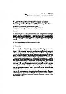
Eq. (7) represents a discretisation of the crack intensity range where λmax is the maximum potentially identifiable crack intensity and g max the chosen relevant integer value. According to the latter approach, the location of the possible cracks ξ k is associated to the chosen discretisation, that can be adaptive if convenient, as better described in the following sections, according to the desired accuracy. As an example, a schematic layout of the adopted discretisation strategy is reported in Figure 1 for the case of a pinned-pinned beam with three cracks together with the displacement measurement sensors.
Since the total number of possible damage configurations, with different locations and intensity, may be large, according to the chosen number N of nodes, it is extremely important to have an automatic procedure able to provide the optimal solution within reasonable computing time. To this aim a genetic algorithm strategy is adopted in what follows to select the damage scenario which best suits the experimental data.
Figure 1. The considered beam discretisation for crack identification. Circles indicates nodes and the associated integer numbers indicate the crack intensity.
4. Optimization procedure by means of a Genetic Algorithm A “genetic algorithm” is an adaptive stochastic method that mimics the Darwinian evolution, which is based on an opportune combination of random mutations and natural selection, in order to numerically find optimal values of some specific function. The algorithm acts over a population of P potential solutions by applying, iteratively, the “survival of the fittest” principle; in such a way it produces a sequence of new generations of P individuals that evolves towards a stationary population where the large majority of surviving solutions do coincide and approach as much as possible the real solution of a practical problem [49,50]. In order to translate into this scenario the damage parameter identification problem of a multicracked beam, a genetic algorithm based identification procedure, developed on the basis of the the objective function discretisation presented in the previous section, is here described.
The genetic algorithm defined in this work operates on a population composed of P individuals, called chromosomes, coded as strings of integer numbers g k , k = 1,…, N , called genes, each one representing the intensity of the possible damage present in the k-th node of the beam at abscissa ξ N , k = 1,…, N (gk = 0 means that no crack is present at the corresponding node). k
A generic chromosome Ci of the population (i = 1, …, P) can be therefore represented as the
(
)
following sequence of genes: Ci ≡ g1 , g 2 ,…, g k ,…, g N with 0 ≤ gk ≤ gmax . The number of genes per chromosome with gk > 0 will be denoted as Σ in what follows for calculation purposes. According to the chosen definition, the overall number of possible different chromosomes (hence the maximum dimension of the initial population) is Pmax = (gmax + 1)N, a quantity which rapidly increases with N even for small values of gmax (for example, if gmax = 2 and N = 22, one obtains Pmax ≈ 31109). The above reported definition for the chromosomes is deeply different from similar studies proposed in the literature. However, a similar choice of chromosome can be found in [51] with reference to stiffness identification problems over diffused portions of the beam. In the identification procedure proposed in this work, the number of cracks nc that can be identified is limited only by the number of measurements M experimentally acquired by the experimental test. Precisely, since position and intensity of each crack have to be identified, for a well posed inverse problem, the number nc of cracks potentially identifiable is equal to
nc = int ( M 2) . The task of the genetic algorithm consists in exploring the space of all possible chromosomes, by means of an evolutionary law rather than a precise analytical or systematic law, in search of the damage scenario maximizing a suitable fitness function, that improves as the objective function O(Ci) decreases. The fitness function here proposed and adopted is defined as follows:
F (Ci ) = K − O (Ci ) − h ( Σ, nc )
(8)
where K is an arbitrary constant, such that F > 0 for every possible chromosome; for the applications reported in the following sections K = 150, without loss of generality, is assumed. The last term h ( Σ, nc ) in Eq. (8) is a supplementary cost function, which has to be minimized in order to guide the selection process towards the sub-space of chromosomes compatible with nc and defined as follows:
Σ − nc ⎧ ⎪ h ( Σ, nc ) = ⎨ 0 ⎪0.01/ ( n − Σ + 1) c ⎩
if if if
Σ > nc Σ = nc Σ < nc
(9)
According to the definition in Eq. (9), in case Σ > nc the cost function takes positive integer values and, as a consequence, the correspondent chromosome will be disadvantaged. On the other hand, when the number Σ of genes with gk > 0 is equal or less than the potentially identifiable number nc of damages, the cost function could be either zero or a small positive value which decreases in a measure proportional to (nc – Σ). In a few words, the role of the cost function h ( Σ, nc ) is to favour the chromosomes with Σ ≤ nc with respect to those chromosomes containing more cracks than nc (strictly dependent on the number of available measures
nc = int ( M / 2 ) ). Therefore, the proposed genetic algorithm is clearly devoted to the solution of well posed inverse problems where multiple cracks can uniquely be identified by means of the available measurements, i.e. n ≤ nc . On the contrary, identification problems based on static tests performed with an insufficient number of measurements with respect to the actual number of cracks (i.e. n > nc ) are clearly avoided with the proposed procedure and can be easily recognised by low values of the fitness function. Bearing in mind that the fitness associated to each chromosome provides somehow a measure of its survival probability under the pressure of the natural selection process, in what follows the details of the proposed identification procedure are reported.
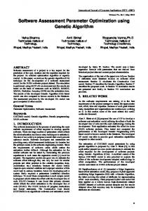
Starting from the initial population of P chromosomes, randomly chosen among the Pmax , a new generation of P chromosomes is created from the old one, where chromosomes with high fitness scores are more likely to be chosen as parents than those with low fitness scores. The selection method adopted in this paper is called tournament selection, with a tournament size of three: this means that groups of 3 chromosomes are drawn randomly from the old generation, and the one with the highest fitness in each group is chosen to become a parent. Children can be created by either a single or a couple of parents. A single parent child is generated as a clone of its parent, a two parent child is generated by a process that is the digital analogue of sexual recombination, i.e. the child inherits part of his genetic material from one parent and part from the other one (crossing-over). The percentage of population subjected to the crossing-over is tuned by an opportune parameter, called “crossover-rate”. The remaining part of the population will be created by the cloning procedure. Once the new generation is created, there is also a chance (regulated by a parameter called “mutation-rate”) that random mutations will occur at level of the single genes gk of the child chromosomes, and some of them will be changed into new ones. In Figure 2 a sketch of these three operations is summarised. By repeating the above selection process for a given number of generations, the chromosomes with the highest fitness will be progressively selected in the space of all the possible combinations and will quickly spread among the population reducing the diversity of the individuals, until likely only one of them will survive, hopefully, the one with the maximum fitness, representing the damage scenario in agreement with the experimental test. Differently from other optimisation methods, genetic algorithms are recognised for the ability to jump out of local minima in view of their independence of gradient based procedures. However, being based on initial random choices, a genetic algorithm should be launched many times (defined as events) each time starting from a different initial population, in order to obtain more chances to reach the fitness global maximum.
Figure 2. Natural selection process through tournament with size of three. Boxes in dark grey represent chromosomes with higher fitness.
It is worth stating that the number of operations to be conducted during the selection process is strictly dependent on the fitness evaluation of each single chromosome. To this regard the procedure herein proposed is highly performant since the fitness in Eq. (8) requires the evaluation of transversal displacements based solely on the explicit closed form solution reported in Eq. (3) without any additional numerical effort.
5. The Genetic Algorithm based Software “DIGA” The procedure described in the previous sections has been implemented in an original software code written in the NetLogo agent-based programming language [47]. NetLogo is a freeware multiplatform environment with a powerful high level programming language and with a very ductile and versatile user interface. The NetLogo platform was natively developed for agent based simulations and for modelling the behaviour of complex systems. The idea is to harness the power of the NetLogo graphical user interface and the versatility of its agent-oriented programming language in order to create a user-
friendly original software, called “DIGA” (Damage Identification with Genetic Algorithms), for the automatic damage identification in cracked beams.
Figure 3. Top: Graphical aspect of the user interface of the program in the NetLogo environment for a generic damage scenario. Bottom: Enlargements of the Fitness Plot and the Diversity Plot.
In the top panel of Figure 3 the final layout of the user interface in the NetLogo environment, for a generic damage scenario in a simply supported beam subjected to a uniform vertical load and discretised with an arbitrary number of nodes, is reported. The interface is visually organized in three parts: a) the left part, dedicated to the input parameters for the number of nodes, the number and location of measurements points and the type and intensity of the loading; b) the central part, where the structure is visualized in the World of NetLogo, which is a two-dimensional rectangular box endowed with a customisable Cartesian reference system, and the results of the
identification procedure are reported in an opportune output window; c) the right part, in which the input parameters for the genetic algorithm (i.e. the population size, the crossover-rate, the mutation-rate and the desired number of generations) can be chosen and both the fitness function and the diversity between the generated chromosomes are plotted as functions of the number of generations. In the bottom panels of the same figure, the two plots with the behaviour of the average fitness and the diversity are reported in a larger scale. The diversity parameter evaluates how much 'disagreement' between chromosomes does exist in the current population and it is based on the well known Hamming distance, which quantifies the percentage of genes which have different values in any couple of chromosomes. As it can be seen, increasing the number of generations, the fitness converges towards its (local or global) maximum value while the diversity goes to zero, meaning that the winning chromosome tends to spread among the population.
6. Numerical applications In this section several numerical examples of the proposed identification procedure are presented. The applications are reported in two different subsections: the first regarding singlecracked beams, the second regarding multi-cracked beam-like structures. With regard to the identificatin of single cracks, a code validation based on numerically simulated data is first presented, then, two case studies show the effectiveness of the proposed approach with respect to an experimental test and to other data available in the literature. The sensitivity of the proposed approach to the positions of the measured displacements is also investigated together with the influence of the instrumental errors on the identification procedure. The second subsection is devoted to multi-cracked beams. Again, the procedure is validated first
by identifying cracks along the span of a beam by numerically simulated displacement data, in which the data are generated by means of the presented closed form solution. Then the proposed procedure is applied for multiple crack identification to verify the robustness of the procedure when the number of cracks to be identified is not equal to the amount of expected ones.
6.1 Single cracked beams The first numerical application here presented aims at validating the implemented code by simulating the experimental dispacement measurements with the closed form solution in Eq. (3). A pinned-pinned beam subjected to a uniform distributed load is considered with a single crack of flexibility λ1=0.07 located at the normalised abscissa ξ1=0.6 (Figure 4).
Figure 4. Identification of a single crack.
The correspondence between the crack flexibility and depth can be performed according to different models proposed in the literature [19,21,22,52]; in this paper the crack compliance, closely related with its flexibility, is computed according to the model proposed in [52], under the hypothesis of rectangular cross section. In particular, considering a slenderness of the beam equal to h L = 0.05 the flexibility λ1 corresponds to a crack depth d / h = 0.336 , where h is the height of the cross section and d the depth of the crack.
In this simulation, and in all the others reported in the paper, the same opportune values of the input parameters for the genetic algorithm, chosen through several preliminary tests, are adopted: the crossover and the mutation rates are respectively set equal to 80% and 1%, the total number of generations is fixed at 150 and initial populations of P = 100 individuals are considered. For this application, a spatial discretisation with N = 19 nodes and a crack intensity discretisation of gmax = 10 possible damage levels up to λmax = 0.1 with Δλ = 0.01 , according to Eq. (7), are adopted. Notice that, in this case, the space of the possible chromosomes, whose dimension is 6.115909044841455*1019, contains the exact cracked configuration. In fact, the chromosome characterized by 18 zeros and the value of 7 at the 12th position, i.e.
Cexact ≡ (0,0,0,0,0,0,0,0,0,0,0,7,0,0,0,0,0,0,0) , corresponds exactly to the configuration to be identified. When no instrumental errors are introduced, the numerical procedure should be able to recover the correct chromosome irrespectively of the applied load intensity. For the considered case two measures are considered at the locations ξm1=0.1 and ξm2=0.9, and the corresponding displacements, due to a uniformly distributed normalised load intensity qo = 50 , are 𝑢!! = 0.221175 and 𝑢!! = 0.229575 obtained by Eq. (3). To verify the robustness of the algorithm 100 events have been performed; the correct chromosome has been found by the procedure in 98 cases in a very short computing time of 6.1 min. The results are spread around the mean value with standard deviations of 0.016 and 0.002 for position and intensity, respectively. 6.1.1 The influence of the measurement locations on the identification of crack parameters The two measurement points in the previously described application have been set at the left and at the right of the cracked cross section in accordance to the sufficient conditions formulated in the literature for a correct crack identification [39,40]. The analytical procedure proposed in the the latter papers show clearly that, in case the measurements are detected differently from the above requirement, an erroneous crack parameter identification is reached and the reader is
therein carefully warned. For this reason the influence of the position of the N = 2 measurement points on identified values is here studied to test the robustness of the genetic algorithm based proposed procedure.
Figure 5. Identification of a single crack for different locations of two measurement points.
As shown in Figure 5, a pinned-pinned beam in presence of a single crack with intensity
λ1=0.07 and subjected to a uniform vertical load is considered. Two different crack locations are analysed: case 1) ξ1=0.33 in Figures 5a-5b; case 2) ξ1=0.73 in Figures 5c-5d. For each configuration one of the two measurement points is set at a fixed position while the influence of the position of the other measurement point is studied: case 1) ξm1=0.1 fixed and ξm2 variable from 0.2 to 0.9;
case 2) ξm1 variable from 0.1 to 0.8 and ξm2=0.9. For each pair of measurement points the displacements given by the closed form solution in Eq. (3) were employed (without introducing any error) by the genetic algorithm to identify the crack properties over 10 events. The identified location of the crack is reported in terms of its mean value together with a representation of the standard deviation. The results show that, when the two measurement points are both on the same side of the crack, the identified mean values are sensibly different from the real ones, and the corresponding standard deviations are affected by high values. On the contrary, when the two measurement points are located at opposite sides of the crack, i.e. when the location of the varying measurement crosses the crack, the identified mean values of both position and intensity are very close to the real ones and the standard deviation of the obtained results turn out to be sufficiently small. The latter aspect seems to be a confirmation of what stated in [39,40] with respect to the optimal location of the measurement points, however it represents a rather different perspective to observe the same property.
6.1.2 Comparison with available data in the literature and remeshing procedure The following application is a comparison with other results provided in the literature [28] and aims at identifying a single crack in a pinned-pinned beam subjected to a concentrated vertical load of normalised intensity F1 = 0.00175 at the abscissa ξ F1 = 0.7143. The crack parameters are, as reported in [28], ξ1=0.57143 and λ1=0.086785, where the crack intensity λ1 is related to the crack depth d h by means of the model proposed in [52]. In this case the displacement measurements are taken at the abscissae ξm1=0.14286, ξm2=0.85714 the corresponding normalised displacements, obtained by the closed form solution in Eq. (3), without considering any noise or measurement error, are: 𝑢!! = 1.22 ∗ 10!! , 𝑢!! = 1.6 ∗ 10!! . It is worth to notice that, for the case under study, considering a beam axis discretisation with N = 19 nodes (i.e Δξ N = 0.05 ) and a crack intensity discretisation characterized by 10 levels of
damage ( Δλ = 0.01 and λmax = 0.1) no possible chromosome is able to correctly identify the actual location and intensity of the crack. In fact, given the adopted discretisation, the actual position and intensity of the existing crack to be detected does not belong to the overall number of possible different chromosomes Pmax . In order to identify the crack with the desired precision, an iterative procedure, based on a more detailed spatial discretisation of a restricted portion of the beam (re-meshing), is here employed. At the generic i-th iteration a new crack position discretisation is introduced in a restricted beam portion centred around at the crack position identified in the (i-1)-th iteration. Consistently, a more refined discretisation of the crack intensity values is also adopted in the i-th iteration around the previously identified value. In each iteration the discretisation resolution is doubled, i.e. Δξ Ni = Δξ Ni−1 / 2 , Δλi = Δλi −1 / 2 . The latter procedure, representing an application of the bisection method, allows to achieve the desired precision for the crack location and the crack intensity identification.
Figure 6. The proposed re-meshing procedure for crack identification
According to the above described iterative remeshing procedure, four iterations with increasing mesh resolutions were performed, leading to the results shown in Figure 6 where the identified values of the damage parameters over 10 events are reported together with the step amplitude. As it can be observed the proposed re-meshing procedure allows to achieve very good results even with a small number of nodes (and therefore of chromosomes), thus drastically reducing the computing time. It is worth to notice that the identified values correspond to the maximum possible precision compatible with the level of the considered discretisation. In the following sub-section the latter application will be the object of further investigation to assess the sensitivity of the adopted identification strategy with respect to instrumental errors.
6.1.3 Sensitivity of the procedure to instrumental errors In order to assess the robustness of the procedure with respect to possible instrumental errors in this section the previously described application (see [28]) is re-analysed by corrupting the input data. Precisely, the available displacement measurements, simulated by means of the exact closed form solution in Eq. (3), are modified by adding a random instrumental absolute error
ε = ε L as follows: u ej = u cj + ε R
j = 1,..., M
(10)
where M = 2 and R is a zero mean random variable uniformly distributed in [−1 ÷1] . Figure 7 shows the normalised errors ηξ and ηλ on the identified crack position and intensity, respectively, for increasing values of the instrumental error ε in the range [0-0.0000015], defined as follows
⎛ ξi − ξ r ⎞ ⎟ ⎝ ξr ⎠ ⎛ λ − λr ⎞ ηλ = µλ ⎜ i ⎟ ⎝ λr ⎠
ηξ = µξ ⎜
(11)
where the subscripts i and r stand respectively for identified and real, while µξ and µλ are the mean values of the identified crack position and intensity, respectively, calculated, for each value of the normalised instrumental error ε , over 5 different realizations of the random distributions of the random number R appearing in the corrupted displacement measurements in Eq. (10).
Figure 7. Sensitivity of the identified damage parameters to increasing instrumental error: (a) damage location and (b) intensity.
In order to improve the accuracy of the obtained results in the same Figure 7 the same normalised error in terms of damage position and intensity are reported when a supplementary measure is added in the middle cross section of the beam. The simulated displacement value at the abscissa ξm3=0.5, which turns out to be 𝑢!! = 3.316 ∗ 10!! , has been also considered affected by an instrumental errors according to Eq. (10). The maximum normalised instrumental error corresponds to a percentage error in the measures which ranges between 4.5% and 12.5% according to the selected measure. As it can be clearly observed, as the measurement absolute error ε increases also the identified values tend to be less
precise; in any case the error in the identification of both locations and intensity of the cracks is comparable with the percentage displacement measurement error that ranges, in the case of the maximum normalised instrumental error, between 13,1% and 23.7% . As it can be clearly observed from the figures, the introduction of the further data, which theoretically would not be necessary in order to identify two parameters, turns out to be very effective for the solution accuracy improvement of the inverse problem in presence of instrumental errors. The latter aspect represents a significant advantage with respect to the explicit solutions available in the literature [28] which rely exclusively on two measurements for each crack. Furthermore, the possibility of using a larger number of measurements than those strictly needed, allows overcoming the annoying problem of the correct disposal of the measurement points on the left and right side of the crack. Ideally the whole deflection profile could be accounted for. 6.1.4 Comparison with an experimental test The application reported in this sub-section is devoted to the validation of the procedure with an experimental test whose results are available in the literature [53]. A clamped-clamped aluminium beam (E=570.0 GPa, ρ=52.703103 kg/m3) with length
L = 60cm and with a rectangular cross section (width d = 5cm and height h = 0.6cm ) is studied (Figure 8). The beam presents two symmetric cuts at the abscissa of 25.5 cm, such that d/h=0.5, corresponding to the normalised damage parameters ξ1 = 0.425 and λ1 = 0.03 . The beam is subjected to two load scenarios characterized by a vertical concentrated load of F1 = 50 N (normalised value F1 = 0.2857 ) at the abscissae 15 cm and 30 cm, respectively. The adopted beam axis discretisation takes into account 99 equally spaced nodes and in order to identify two damage parameters by the measurements, inevitably affected by instrumental errors, three values of the measured displacements are taken into account, as suggested in the previous sub-section, as reported in Figure 8.
Figure 8. Clamped-clamped beam with a single crack
Table 2. Identification procedure on a clamped-clamped cracked beam
Load
Measure
Measured
mean
stdev
mean
stdev
abscissa
abscissa
displacement
ξ1
ξ1
λ1
λ1
0.15
0.000328167
0.35
0.001179983
0.358
0.173
0.048
0.0204
0.75
0.0007495
0.15
0.000319667
0.35
0.000813833
0.4266
0.153
0.0299
0.026
0.75
0.000304667
0.5
0.25
The mean values, over 10 events, of the identified damage parameters “mean ξ1 ” and “mean λ1 ” together with the related standard deviations “stdev ξ1 ”, “stdev λ1 ” are reported in the Table 2. As it can be noticed the damage parameters are identified with reasonable precision, in particular for the un-symmetric load condition. 6.2 Multi-cracked beams The identification of multiple cracks represents a more challenging issue with respect to the case of a single crack and, in the present paragraph, it will be shown that the proposed procedure is able to identify an arbitrary number of cracks with accuracy. 6.2.1 Identification of two cracks A first validation of the above statement has been obtained by considering a cantilever beam subjected to a uniform distributed load and affected by two concentrated cracks at the abscissae
ξ1=0.2 and ξ2=0.4 with an intensity of λ1=0.02 and λ2=0.04, respectively, (Figure 9).
Figure 9. Cantilever beam with two concentrated cracks
For this application a spatial discretisation with 99 nodes ( Δξ N = 0.01) and a crack intensity discretisation of 10 possible damage levels ( Δλ = 0.01 ) are adopted. With the considered data and the adopted discretisation, the algorithm is able again to lead to the
exact cracked configuration since the latter is included in the space of the possible chromosomes. In fact, the chromosome characterized by 97 zeros and the values of 2 at the 19th position and 4 at the 39th position corresponds exactly to the configuration to be identified. When no instrumental errors are introduced, the numerical procedure is able to recover the correct chromosome irrespectively of the applied load intensity. For the case under study four measurements are considered at the locations ξm1=0.25, ξm2=0.35, ξm3=0.65 and ξm4=0.95, and the corresponding displacements due to a uniformly distributed load of intensity qo = 50 are 𝑢!! = 0.00913802, 𝑢!! = 0.03426302, 𝑢!! = 0.42088802 and 𝑢!! = 1.79988802 which will be considered as simulated experimental values in the application. The damage scenario with the best fitness over 100 events is associated to the identified values reported in Table 3. Table 3. Identification procedure on a double cracked cantilever beam
Real
0.2
0.4
0.02
0.04
Identified
0.2
0.4
0.02
0.04
6.2.2 Identification of more than two cracks In order to investigate on the performance of the proposed procedure for the identification of an increasing number of cracks, a simply supported beam with n = 1,…,5 and subjected to a uniform transversal load is here considered. The cracks are equally spaced along the beam axis and characterised by the same severity ( λi = 0.05 , i = 1,…,5 ). The measurement points have been set according to the following formulas:
⎧ 1 ⎛ 1⎞ ⎪ξ m,2i −1 = n + 1 ⎜ i − 3 ⎟ ⎪ ⎝ ⎠ ⎨ ⎪ξ = 1 ⎛ i + 1 ⎞ ⎪⎩ m,2i n + 1 ⎜⎝ 3 ⎟⎠
i = 1,..., n
(12)
specifically devised to respect the condition that the number of measurements is M = 2n and
each crack lies between two successive measurement positions. Regarding the adopted discretisation, 99 nodes were considered ( Δξ N = 0.01) and a crack intensity discretisation of 10 possible damage levels ( Δλ = 0.01 ), which correponds to a maximum level of damage λmax = 0.1. Table 4. Real and identified damage parameters in five different configurations, with an increasing number of cracks
n
1
2
3
4
5
Real
0.5
0.05
Identified
0.5
0.05
Err [%]
0.00
0.00
Real
0.33
0.05
0.67
0.05
Identified
0.33
0.05
0.67
0.05
Err [%]
0.00
0.00
0.00
0.00
Real
0.25
0.05
0.5
0.05
0.75
0.05
Identified
0.21
0.05
0.5
0.06
0.77
0.05
Err [%]
4.00
0.00
0.00
10.00
2.00
0.00
Real
0.2
0.05
0.4
0.05
0.6
0.05
Identified
0.17
0.05
0.41
0.05
0.61
0.06
Err [%]
3.00
0.00
1.00
0.00
1.00
10.00
Real
0.17
0.05
0.33
0.05
0.5
0.05
0.67
0.05
0.83
0.05
Identified
0.19
0.05
0.39
0.06
0.54
0.05
0.70
0.06
0.86
0.03
Err [%]
2.00
0.00
3.00
10.00
4.00
0.00
3.00
10.00
3.00
20.00
The identified locations and intensities of n = 1,…,5 cracks are reported in Table 4 with the corresponding real values, considering, for each case, the damage scenario with the best fitness over 100 events. The errors reported in Table 5 are defined as follows:
Damagelocation :
Errξ [%] = 100 ⋅ ξi − ξ r
Damageintensity :
Errλ [%] = 100 ⋅
λi − λr λmax
(13)
for the identified crack position and intensity, respectively.
Figure 10. Errors on identified parameters of each crack in different damage scenarios Red= real values; blue= identified values
In Figure 10 the errors on the identified damage parameters regarding each crack, due to the adopted chromosome discretization, are plotted for the different damage scenarios with an increasing number of cracks from n = 1 to 5 starting from the top of the figure. For every damage scenario each crack, either real or identified, is indicated reporting above the corresponding abscissa a slim rectangle in which the intensity λ is represented by a coloured filling of different levels varying from 0 to 0.1 (red is the real crack intensity, blue is identified crack intensity). The cases of a single and two cracks, reported in Figure 11, show the best performance characterised by zero errors both on the identified locations and intensities. When the number of cracks increases different errors arise both on the identification of the location and the intensity of each single crack which are, however, contained in acceptable ranges. 6.2.3 Robustness of the procedure A crucial aspect in damage identification is the unknown number of cracks to be detected. In fact, while the maximum number of potentially identifiable cracks is equal to half the measurement points, the real number could be equal or less than that value. This circumstance may therefore produce very different damage scenarios which often correspond to similar values of the measured displacement thus deeply complicating the identification procedure. In the following it will be shown that the proposed procedure is capable of identifying a number of cracks lower than those potentially identifiable, i.e. n < nc , with sufficient accuracy. First, a numerical example of a single cracked ( n = 1 ) pinned-pinned beam subject to an uniform transverse load is considered in two scenarios with a different number of potentially identifiable cracks ( nc = 2,3 ). The measurement points ( M = 4 for nc = 2 ; M = 6 for nc = 3 ) are uniformly distributed along the beam. For this application a spatial discretisation with 99 nodes ( Δξ N = 0.01) and a crack intensity discretisation of 10 possible damage levels ( Δλ = 0.01 ) are
adopted for each of the 100 different events.
The results of the identification procedure, obtained by data simulated with the closed form solution in Eq. (3), are reported in Table 5 and demonstrate that the winning chromosome reaches the maximum possible fitness value. In fact, the proposed strategy is able, also in view of the adopted discretisation, to identify exactly the damage parameters even though the number of cracks is lower than those potentially identifiable strictly dependent on the number of available measurements. Table 5. Identification procedure on a single cracked pinned-pinned beam with, respectively, two or three potentially identifiable cracks 2
nc
3
Real
Identified
Real
Identified
ξ1
0.8
0.8
0.71
0.71
λ1
0.08
0.08
0.03
0.03
As a second example, two cracks ( n = 2 ) occurring on a pinned-pinned beam subjected to a uniform transverse load are to be identified in two different case by the knowledge of M = 6,8 displacement measurements data corresponding to nc = 3, 4 potentially identifiable damages, respectively. Table 6. Identification procedure on a double cracked pinned-pinned beam with three and four potentially identifiable cracks 3
nc
4
Real
Ident.
Real
Ident.
0.35
0.35
0.25
0.25
0.05
0.05
0.05
0.05
0.8
0.79
0.50
0.49
0.05
0.05
0.05
0.05
According to the known conditions, the measurement points are double than the potentially identifiable cracks and are uniformly distributed along the beam. The same crack position and intensity discretisations of the previous example are adopted, as well as the same parameters for the genetic algorithm. The exact results are recovered by the proposed procedure based on uncorrupted measurement data simulated by means of Eq. (3) as shown in Table 6. The last application concerns a clamped-clamped beam with three cracks ( n = 3 ) subjected to a concentrated load at the abscissa ξ F = 0.4 with M = 8 uniformly distributed measurement points, and nc = 4 potentially identifiable cracks. The results of the proposed identification procedure based on uncorrupted measurement data simulated by means of Eq. (3) show good accuracy as reported in Table 7 which includes both the real and the identified data. Table 7. Identification procedure on clamped-clamped beam with three cracks when four damage are potentially identifiable Real
Ident.
0.25
0.26
0.05
0.03
0.5
0.5
0.05
0.05
0.75
0.76
0.05
0.04
7. Conclusions In this paper a novel strategy for the static identification of cracks in beam-like structures is presented. The identification procedure is based on a closed form solution which allows accounting for an arbitrary number of cracks without enforcing continuity conditions at the damaged section, thus making the procedure robust and numerically effective. The closed form expressions are coupled with the genetic algorithm optimization method through an original definition of the
chromosomes. An original implementation of the method in the agent based software environment NetLogo is performed. The proposed strategy is able to detect an arbitrary number of cracks either when it coincides with the maximum number of potentially identifiable cracks (equal to half the measurement points), or when it is less than that value. Validations of the method are provided for single and multi-cracked beams, for different boundary conditions and load scenarios. The influence of the measurement points and instrumental errors is studied showing the advantage of the proposed procedure with respect to other strategies available in the literature.
References [1] Adams R.D., Cawley P., Pye C.J., Stone B.J.: A vibration technique for non-destructively assessing the integrity of structures. J. Mech. Eng. Sci. 20, 93–100 (1978) [2] Gudmundson P.: Eigenfrequency changes of structures due to cracks, notches and other geometrical changes. J. Mech. Phys. Solids 30(5), 339–353 (1982) [3] Hearn G., Testa R.B.: Modal analysis for damage detection in structures. J. Struct. Eng. 117(10), 3042–3063 (1991) [4] Liang R.Y., Hu J., Choy F.: Theoretical study of crack-induced eigenfrequency changes on beam structures. J. Eng. Mech. (ASCE) 118, 384–396 (1992) [5] Morassi A.: Crack-induced changes in eigenparameters of beam structures. J. Eng. Mech. (ASCE) 119, 1798–1803 (1993) [6] Narkis Y.: Identification of crack location in vibrating simply supported beams. J. Sound Vib. 172, 549–558 (1994) [7] Vestroni F., Capecchi D.: Damage detection in beam structures based on frequency measurements. J. Eng. Mech. (ASCE) 126(7), 761–768 (2000) [8] Morassi A.: Identification of Two Cracks in a Simply Supported Beam from Minimal Frequency Measurements, Journal of Vibration and Control 7 (5), 729-739 (2001)
[9] Law S.S., Lu Z.R.: Crack identification in beam from dynamic responses J. Sound Vib. 285 (45), 967–987 (2005) [10] Ren W.X., De Roeck G., Structural damage identification using modal data. I: Simulation verification, Journal of Structural Engineering ASCE, 128, 87-95 (2002) [11] Ren W.X., De Roeck G., Structural damage identification using modal data. II: Test verification, Journal of Structural Engineering ASCE, 128, 96-104 (2002) [12] Caddemi S, Caliò I., Exact reconstruction of multiple concentrated damages on beams Acta Mechanica 225, 3137-3156 (2014) [13] Sanayei M, Onipede O, Damage assessment of structures using static test data AIAA journal 1991; 29 (7): 1174-1179. [14] Rezaiee-Pajand M, Kazemiyan MS, Aftabi S A, Static damage identification of 3D and 2D frames Mechanics Based Design of Structures and Machines 2014; 42 (1): 70-96. [15] Greco A, Pau A, Detection of a concentrated damage in a parabolic arch by measured static displacements Structural Engineering and Mechanics 2011; 39(6): 751-765. [16] Raghuprasad BK, Lakshmanan N, Gopalakrishnan N, Sathishkumar K, Sreekala R, Damage identification of beam-like structures with contiguous and distributed damage Structural Control and Health Monitoring 2013; 20(4): 496-519. [17] Irwin GR, Analysis of stresses and strains near the end of a crack traversing a plate Journal of Applied Mechanics 1957; 24: 361-364. [18] Irwin GR, Relation of stresses near a crack to the crack extension force, 9th Congr. Appl. Mech., Brussels, 1957. [19] Rizos PF, Aspragathos N, Dimarogonas AD, Identification of crack location and magnitude in a cantilever beam from the vibration modes Journal of Sound and Vibration 1990; 138(3): 381388. [20] Gounaris G, Dimarogonas AD, A finite element of a cracked prismatic beam for structural analysis Computers and Structures 1988; 28: 309-313.
[21] Liebowitz H, Claus Jr. WDS, Failure of notched columns Engineering Fracture Mechanics 1968; 1: 379-383. [22] Liebowitz H, Vanderveldt H, Harris DW, Carrying capacity of notched column International Journal of Solids and Structures 1967; 3: 489-500. [23] Ostachowicz WM, Krawczuk C, Analysis of the effect of cracks on the natural frequencies of a cantilever beam Journal of Sound and Vibration 1991; 150(2): 191-201. [24] Paipetis SA, Dimarogonas AD, Analytical Methods in Rotor Dynamics Elsevier Applied Science, London, 1986. [25] Gudmnundson P, The dynamic behaviour of slender structures with cross-sectional cracks Journal of the Mechanics and Physics of Solids 1983; 31: 329–345. [26] Sinha JK, Friswell MI, Edwards S, Simplified models for the location of cracks in beam structures using measured vibration data Journal of Sound and Vibration 2002; 251(1): 13–38. [27] Freund LB, Hermann G, Dynamic fracture of a beam or plate in plane bending Journal of Applied Mechanics 1976; 76: 112-116. [28] Caddemi S, Greco A, The influence of instrumental errors on the static identification of damage parameters for elastic beams Computers and Structures 2006; 84(26-27): 1696-1708. [29] M. Rucka, K. Wilde, Crack identification using wavelets on experimental static deflection profiles Engineering Structures 28, 279-288 (2006) [30] G. Buda, S. Caddemi, Identification of Concentrated Damages in Euler-Bernoulli Beams under Static Loads Journal of Engineering Mechanics ASCE 133(8), 942-956 (2007) [31] B. Chen, C. Zang, Artificial immune pattern recognition for structure damage classification Computers & Structures 87, 1394-1407 (2009) [32] S.A. Moezi, E. Zakeri, A. Zare, M. Nedaei, On the application of modified cuckoo optimization algorithm to the crack detection problem of cantilever Euler–Bernoulli beam Computers & Structures 157, 42-50 (2015) [33] C.E. Braun, L.D. Chiwiacowsky, A.T. Gòmez, Variations of Ant Colony Optimization for the
solution of the structural damage identification problem Procedia Computer Science 51, 875-884 (2015) [34] M.T. Vakil-Baghmisheh, M. Peimani, M.H. Sadeghi, M.M. Ettefagh, Crack detection in beamlike structures using genetic algorithms Applied Soft Computing 8(2), 1150-1160 (2008) [35] L. Faravelli, F. Marazzi, Stiffness matrices and genetic algorithm identifiers toward damage detection Proceedings of IABMAS’06, Porto, Portugal, (CD-ROM) (2006) [36] M. Mehrjoo, N. Khaji, M. Ghafory-Ashtianyc, Application of genetic algorithm in crack detection of beam-like structures using a new cracked Euler–Bernoulli beam element Applied Soft Computing 13,867-880 (2013) [37] M. Mehrjoo, N. Khaji, Crack detection in a beam with an arbitrary number of transverse cracks using genetic algorithms Journal of Mechanical Science and Technology 28(3), 823-836 (2014) [38] S. Caddemi, M. Di Paola, The Hu–Washizu variational principle for the identification of imperfections in beams International Journal for Numerical Methods in Engineering 75(11), 1259-1281 (2008) [39] S. Caddemi, A. Morassi, Crack detection in elastic beams by static measurements International Journal of Solids and Structures 44, 5301-5315 (2007) [40] S. Caddemi, A. Morassi, Detecting Multiple Open Cracks in Elastic Beams by Static Tests Journal of Engineering Mechanics ASCE 137(2), 113-124 (2011) [41] B. Biondi, S. Caddemi 2007 European Journal of Mechanics A/Solids 26(5), 789-809. EulerBernoulli beams with multiple singularities in the flexural stiffness. [42] S. Caddemi, I. Caliò, F. Cannizzaro, Closed-form solutions for stepped Timoshenko beams with internal singularities and along-axis external supports, Archive of Applied Mechanics 83 (2013) 559-577. [43] S. Caddemi, I. Caliò, F. Cannizzaro, D. Rapicavoli, A novel beam finite element with singularities for the dynamic analysis of discontinuous frames Archive of Applied Mechanics 83(10), 1451-1468 (2013)
[44] S. Caddemi, I. Caliò, F. Cannizzaro, The influence of multiple cracks on tensile and compressive buckling of shear deformable beams International Journal of Solids and Structures 50(20-21), 3166-3183 (2013) [45] S. Caddemi, I. Caliò, The exact stability stiffness matrix for the analysis of multi-cracked frame structures Computers & Structures 125, 137-144 (2013) [46] S. Caddemi, I. Caliò Exact closed-form solution for the vibration modes of the Euler–Bernoulli beam with multiple open cracks Journal of Sound and Vibration, 327 (3–5) (2009), pp. 473–489 [47] U. Wilensky NetLogo, http://ccl.northwestern.edu/netlogo, Center for Connected Learning and Computer-Based Modeling. Northwestern University,
Evanston, IL 1999. [48] Caddemi S, Morassi A, Multi-cracked Euler-Bernoulli beams: Mathematical modeling and exact solutions International Journal of Solids and Structures 2013; 50: 944-956. [49] Goldberg DE. Genetic algorithms in search, optimization and machine learning. AddisonWesley, USA; 1989. [50] Holland JH. Adaptation in natural and artificial systems. MIT Press, USA; 1992. [51] S. Casciati, Stiffness identification and damage localization via differential evolution algorithms Structural Control and Health Monitoring 15, 436-449 (2008) [52] Bilello, C., 2001. Theoretical and experimental investigation on damaged beams under moving systems. Ph.D. Thesis, University of Palermo, Palermo, Italy. [53] X. Wang, N. Hu, H. Fukunaga, Z.H. Yao, Structural damage identification using static test data and changes in frequencies Engineering Structures 23, 610-621(2001)