Available online at www.sciencedirect.com Available online at www.sciencedirect.com
ProcediaProcedia Engineering 00 (2011) Engineering 15000–000 (2011) 1910 – 1915
www.elsevier.com/locate/procedia
Advanced in Control Engineering and Information Science
Closed-loop identification method of sintering process with part of the inputs controlled WANG Chun-sheng, WU Min∗ School of Information Science and Engineering, Central South University, Changsha, Hunan 410083, China
Abstract Considering the problem existed in open-loop identification method and the characters of sintering process such as time-delay, nonlinear and uncertainty, a closed-loop identification method of sintering process with part of the inputs controlled is proposed for burn-through point (BTP) control in this paper. Based on the mechanism analysis of the sintering process, two kinds of identification experiment situations have been discussed and an unbiased multiple input/output and auto-regressive with external predictive model of BTP for sintering process is established by adopting the closed-loop identification method to describe the dynamic characteristics of the sintering process. Results of industrial experiment show that the model obtained by closed-loop identification method has smaller predictive error and higher precision compared with that obtained by open-loop identification method.
© 2011 Published by Elsevier Ltd. Open access under CC BY-NC-ND license. Selection and/or peer-review under responsibility of [CEIS 2011] Keywords: Sintering process; ARX model; Open-loop identification; Closed-loop identification
1. Introduction Iron ore sintering is an important step in iron-making by the blast furnace route. Sinter, the quality of which has a direct impact on the quality of steel, is a vital raw material for blast furnace. With the development of modern iron-making technology, the optimization control of sintering process plays a key
* Corresponding author. Tel.: +86-731-88830387; fax: +86-731-88876750. E-mail address:
[email protected].
1877-7058 © 2011 Published by Elsevier Ltd. Open access under CC BY-NC-ND license. doi:10.1016/j.proeng.2011.08.356
2
1911
WANG Chun-sheng and WU / Procedia Engineering (2011) 1910 – 1915 WANG Chun-sheng ,et Min al/ Procedia Engineering 0015 (2011) 000–000
role in promoting the competition of iron-making factories. The burn-through point (BTP) is an essential sign for sintering process, and should be controlled well to keep the sintering process stable. By analyzing the thermodynamic process of sintering, some scholars have already proposed a few static, mathematic equations based on the mechanism to describe the sintering process [1-3]. However, many factors of these models can not be measured on site, thereby these models could not be used in controller design. With the development of fuzzy system, neural network and expert system, some scholars adopt intelligent method to establish the BTP prediction model [4]. Recently, the “control oriented system identification” method has become the developing trend in the field of the complex industry process control. Considering the characters of the sintering process such as time-delay, nonlinear and uncertainty, this paper adopts a closed-loop identification strategy, and chose the auto regressive with external model structure. Then, we establish the sintering process model, and finally discuss the experimental results and make some conclusions. 2. Process Description The sintering process considered in this study employs a Dwight-Lloyd (DL) type sintering machine, which is the type widely used in most industrial sintering process. The raw sintering material, which contains coke, limestone, ore, and returning sinter, is first granulated with moisture in a mixer. Then, it is charged on the moving strand to form a bed. Under the ignition hood, the igniter burns gas to ignite the bed. Once the temperature in the top layer of the bed is high enough, the coke starts to burn and the sintering of the ore begins. After the sintering material leaves the ignition hood, the combustion continues by sucking fresh air to the bed through the bellows. The combustion zone gradually progresses and finally the whole bed burns through. The position along the strand where the bed is just thoroughly sintered is called the burn-through point (BTP), which is described by the number of the corresponding bellows. For an optimal operation of the sintering process, the location along the strand where the mixture is burned through and the sintering process is completed, the so-called burn-through point (BTP), is important. It could be described by (1):
BTP =
∫
BTT
0
v(t )dt ,
BTT = H v ⊥
(1)
where v(t) is the instantaneous velocity of the sintering moving strand, BTT (Burn-Through Time) is the time from the igniting time to the time when the layer is burned through, which is decided by the vertical burning speed (v⊥) and the bed depth (H). According to the sintering theory, the temperature of the material layer and the waste gas of the wind box becomes higher and higher. Thus, the BTP could be reflected by the position where the temperature of the waste gas of the wind box is the highest. As shown in (1), the position of the BTP is mainly affected by the vertical burning speed and the strand velocity. The vertical sintering speed has close relationship with the bed depth, the air volume of the blowers, the mix moisture and the permeability of the sinter bed. 3. System Identification Method 3.1. Open-loop identification In the control system, the MIMO linear time invariable (LTI) system described by (2) is adopted to describe the process object. y (t ) = G0 (q, θ )u (t ) + H 0 (q, θ )e(t ) (2)
1912
WANG Chun-sheng and WU Min / Procedia 15 (2011) 1910 – 1915 Author name / Procedia Engineering 00Engineering (2011) 000–000
3
A corresponding model of system (2) is represented by the transfer function matrices G(q,θ) and H(q,θ) which are parameterized by the unknown vector of parameters θ. If the prediction error method is adopted, the prediction errors could be calculated by (3).
ε (t , θ ) = H 0 ( q, θ ) −1 [ y (t ) − G0 (q, θ )u (t )]
(3) When ARX model structure is adopted, the corresponding transfer function matrix of formula (2): G(q,θ)=A(q,θ)-1B(q,θ), H(q,θ)=A(q,θ)-1. Where
A(q, θ ) = I p + A1q −1 + + An a q − n a , B(q, θ ) = B0 + B1q −1 + + Bnb q − nb +1
(4)
Ip is a q dimensional unit matrix, na and nb note model orders. Therefore, in the ARX model structure, the prediction error (3) could be described by the linear regression equation (5): ε (t , θ ) = y (t ) − ϕ T (t )θ (5) where θ T = [ A1 An a B0 Bnb −1 ], ϕ T (t ) = [− y (t − 1) − y (t − na ) u (t ) u (t − nb + 1] is
a
linear
regression matrix composed by the input and output data from a certain time in the past to the time t. If given the data set ZN with a sample size of N, an estimated of the vector of parameters is obtained by minimizing the least-squares criterion VN defined by the optimization problem
θˆN = arg min VN (θ ); VN = θ
1 N
N
∑ε
T
(t , θ )ε (t , θ )
(6)
t =1
The basic idea of the way to solve the optimal problem described by (6) is to transfer the ARX model estimation problem to quadratic programming problem described by (7), and then adopting the corresponding quadratic programming algorithms to obtain the estimated parameter matrix θˆN .
1 2
θˆN = arg min θ T H (t )θ + G T (t )θ , H (t ) = θ
1 N
N
∑
ϕ (t )ϕ T (t ), G (t ) = −
t =1
1 N
N
∑ ϕ (t ) y(t )
(7)
t =1
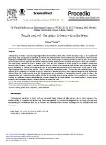
3.2. Closed-Loop Identification The closed-loop control structure of BTP in the practical production process is shown in Fig.1. s(t) r(t)
d(t)
uc(t)
C(q) um(t)
G0(q)
y(t)
Fig. 1 Configuration for BTP closed-loop control
In Fig. 1, u m (t ) = [u 2 (t ) u3 (t ) u 4 (t ) u5 (t )] is defined as input uncontrolled, where u2(t), u3(t), u4(t) and u5(t) denote the bed height, the air volume of the blowers, the mix moisture and the permeability of the sinter bed, respectively; uc (t ) = u1 (t ) is defined as controllable input vector. y(t) is the measured value of BTP, therefore the closed-loop system equation of the sintering process can be described as follows: T
uc (t ) y (t ) = G0 (q) + H 0 (q)e(t ) , uc (t ) = C (q)[r (t ) − y (t )] + s (t ) um (t )
(9)
where r(t) is the given value of the BTP. s(t) is the external incentive signal superimposed on the controller’s output. C(q) is the transfer function matrix of the controller. G0(q) is the system transfer function matrix to be estimated. H0(q) is a monic invertible noise filter. e(t) is multivariate white noise.
4
1913
WANG Chun-sheng and , WU / Procedia Engineering (2011) 1910 – 1915 WANG Chun-sheng et Min al/ Procedia Engineering 0015 (2011) 000–000
Let g(t)=r(t)+C(t)s(t) and system’s open loop gain matrix L(q)=C(q)G(q), then
u (t ) uc (t ) = g (t ) − L(q ) c − C(q )d (t ) um (t )
(10)
The open-loop gain matrix L(q) is divided into two sub-matrixes L1(q) and L2(q) according to whether the input is controllable or not. L( q) = [L1 (q) L2 ( q)] (11)
where L1 (q) is a 1×1 matrix, L2 (q) is a 1×4 matrix. If let S0 = (1 + L1 ( q) ) [1 − L2 (q)] , then (10) can be transferred to be the following formula: −1
g (t ) uc (t ) = S 0 − (1 + L1 ( q)) −1 C ( q)d (t ) um (t )
(12)
From (12), it is clear that the input controlled uc(t) is correlated with the output disturbance d(t) [5-6]. In this paper, we propose an unbiased closed-loop identification method to model the sintering process for BTP control. The basic idea is to eliminate the disturbance factors in the input controlled uc(t) to remove the correlation, and get the system’s input controlled uf(t). Then, the transfer function matrix with input
uˆ = [uˆ Tf u mT ]T and output y(t) are identified and estimated, and the system’s unbiased estimation G0(q) is finally obtained. The identification steps in detail are described as follows. Step1: As g(t), uncontrollable input um(t) and disturbance d(t) are unrelated, (12) can be transferred to
[
the open loop identification problem with input signal r T umT
] and output signal u (t). That is to say, T
c
adopting the prediction error method in chapter 3.1 to get the transfer function matrix S0 ( q,θˆ) . Step2: Based on the transfer function S0 which obtained by estimation, the input controlled without disturbance contribution uf(t) can be described as
g (t ) u f (t ) = S0 (q, θˆ) u m (t )
(13)
Then the process system can be re-written by
u (t ) y (t ) = G0 (q) f + d (t ) um (t )
(14)
and process identification reduces to an open-loop identification problem. Step3: The process transfer function matrix G0(q) can be estimated by adopting the prediction error method in chapter 3.1 and choosing proper model order. 4. Simulation Results Analysis Based on the aforementioned discussion, we conduct an identification experiment on the sintering process of a steel plant to verify the closed-loop identification method proposed. We introduce the selfdefinite external incentive s(t) after the controller output and obtain 10 experiment data sets, every of which contains 1000 data with 30 seconds sampling time. Then, we utilize the method of closed-loop identification to conduct the corresponding identification experiment of 8 data sets, and get the corresponding model set respectively. We use the rest 2 data sets to verify the model in G and conduct the variance estimations of the prediction error of every model to get the model with minimal variance.
1914
WANG Chun-sheng and WU Min / Procedia 15 (2011) 1910 – 1915 Author name / Procedia Engineering 00Engineering (2011) 000–000
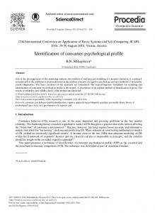
In order to verify the advantage of the closed-loop identification, we use the prediction error method of open-loop identification, to directly estimate the system transfer function matrix from u(t) to y(t). Then, we make a comparison with the result of closed-loop identification, as shown in Fig.2. 23.6
open-loop closed-loop measured
23.4
BTP
23.2 23 22.8 22.6
0
200
400
600
800
1000
1200
1400
1600
1800
2000
Sample (30s) Fig. 2 Results comparison between open-loop and closed-loop identification
5. Conclusions In this paper, a closed-loop identification method with part of the inputs controlled is presented. This closed-loop mechanism transfers the closed-loop problem to opened-loop identification processes. Thus eliminating the correlation between input signs and output disturbances, and overcoming the estimate bias of the classic identification method under the closed-loop condition. The results of experimental simulation show that the ARX model structure could describe the characters of the practical sintering process accurately, and has solved the difficult modeling problem of sintering process. The proposed closed-loop identification strategy, which is of short calculate time and do not need the prior knowledge of feed back controller, provides an effective way to solve the BTP modeling problem, and establishes the foundation for further research in the self-adaptive control and prediction control of the BTP. Acknowledgements The authors would like to thank the financial support provided by the National High Technology Research and Development Program of China (863 Program) under Grant No. 2009AA04Z157. References [1] Dash IR, Rose E. Simulation of a sinter strand process. Ironmaking steelmaking, 1978; 5 (1): 321–328. [2] Hansen JD, Rusin RP, Teng MH. Combined stage sintering model. Journal of the American Ceramic Society, 1992; 75 (5): 1129-1135. [3] Nath NK, DaSilva AJ, Chakraborti N. Dynamic process modelling of iron ore sintering. Steel Research, 1999, 68 (7): 285292. [4] Shang XQ, Lu JG, Sun Y X, LIU J and Ying. YQ. Data-Driven Prediction of Sintering Burn-Through Point Based on Novel Genetic Programming. Journal of Iron and Steel Research, 2010, 17 (12): 1-5.
5
WANG Chun-sheng and WU Min / Procedia Engineering 15 (2011) 1910 – 1915
1400
6
1915
WANG Chun-sheng ,et al/ Procedia Engineering 00 (2011) 000–000 [5] Forssell U, Ljung L. Closed-loop identification revisited. Automatica, 1999, 35 (7): 1215-1770. [6] Leskens M, Van Kessel LBM, Van den Hof PMJ. MIMO closed-loop identification of an MSW incinerator. Control Engineering Practice, 2002, 10 (3): 315-326.