Cluster based Multipath Routing Protocol for Wireless Sensor Networks Suraj Sharma
Sanjay Kumar Jena
International Institute of Information Technology Bhubaneswar, India
National Institute of Technology Rourkela, India
[email protected]
[email protected]
ABSTRACT
2. RELATED WORK
Wireless Sensor Network (WSN) consists of low power sensor nodes. Energy is the main constraint associated with the sensor nodes. In this paper, we propose a cluster based multipath routing protocol, which uses the clustering and multipath techniques to reduce energy consumption and increase the reliability. The basic idea is to reduce the load of the sensor node by giving more responsibility to the base station (sink). We have implemented and compared the protocol with existing protocols and found that it is more energy-efficient and reliable.
Bagheri et al.[2] have proposed the protocol, where nodes are enabled by the GPS system. The cluster head section is based on the remaining energy of the node. The multipath routes are constructed through the cluster heads. A cluster head selects another path, if it fails. Quynh et al.[9] have proposed an event-based multipath clustering protocol. When an event is detected, all nodes near the event will become active. One of the nodes close to the event having maximum residual energy elects itself as the cluster head. The rest of the active nodes join the cluster head and form the cluster. The cluster head chooses the relay node and backup relay node towards the sink to form the multipath. Mazaheri et al.[7] have proposed a QoS base multipath hierarchical routing. Among the nodes in the range r elect the cluster head based on the remaining energy and the distance from the sink. For multipath construction, cluster head chooses the set of cluster heads within the range R (R > r) based on the residual energy, remaining buffer size, signal to noise ratio and distance to the sink. Jin et al.[4] have proposed a Passive Cluster based Multipath Protocol (PPCMP). In this protocol, the node near to the event becomes the candidate cluster head and waits for a certain time. If it does not receive any cluster head advertisement, it becomes the cluster head and broadcasts the advertiserange ment in its range (R). The node resides within R 2 joins the cluster and rest of the nodes up to the range R become the candidate cluster head and follow the same procedure for cluster formation. Branch aware flooding method [8] is used to construct the mutipath between the sink and the source node. For the next time if any source detected the event, the same available set of clusters are used, but new set of multipath is required for data transmission. In the existing protocols [2, 9, 7, 4] the control packet overhead is more, which leads to the higher-energy consumption. It directly affects the lifetime of the network. This protocols give more emphasis on reliability through the mutipath but neglect some QoS parameters such as end-to-end delay, control overhead and network lifetime. Zaman et al.[12] have proposed a protocol where the network is divided among the number of levels. One cluster head is elected in each level. The cluster head collects the data from the nodes of that level and transmits it to the lower-level cluster head using directional flooding technique [5]. Almalkawi et al.[1] have proposed a cross layer based clustered multipath routing. The nodes are heterogeneous and randomly deployed. The sink initiated the cluster formation by broadcasting the control packet and based on re-
Keywords wireless sensor networks, multipath, clustering, energy efficient, routing protocol
1.
INTRODUCTION
WSN consists of low power and low cost embedded devices called sensor nodes. Sensor nodes sense the environment and generate the data for temperature, pressure, motion, fire, humidity and so on. The sensor node sends the data to the base station through the intermediate sensor nodes in multihop environment. In the sensor network with energy constraint environment, the network often requires energyefficient routing protocol to send the data. The data should reach the base station through a reliable path. The reliable path significantly reduces the retransmission of data, which can decrease congestion and energy consumption. So, the sensor node requires appropriate energy-efficient and reliable path for data transmission. In this paper, Cluster base Multipath Routing Protocol (CMRP) is proposed, which addresses the mentioned requirements. In WSN, the clustering technique reduces the data traffic in the network. It helps to minimize the energy consumption in the network. Multipath routing increases the reliability of the network, through many available paths. If the path between the source node and the sink fails, then the source node can choose the path from the available paths. The clustering and multipath technique increases the reliability and energy-efficiency of the network. The rest of the paper is organized as follows: related work is discussed in Section 2. The working principle and algorithm of the proposed model is discussed in Section 3. In Section 4 simulation parameter, results and analysis are discussed.
ACM SIGCOMM Computer Communication Review
15
Volume 45, Number 2, April 2015
ceived signal strength, the powerful nodes become the cluster heads. The cluster heads are classified in different levels. They send the data through the upper level cluster head. A diagnosis based clustering and multipath routing are proposed in [1]. For cluster formation, base station randomly chooses a specific number of candidate cluster heads on certain probability. The candidate cluster head checks the faulty status of each other. Once the faulty node is detected, it is removed from the network. Among the neighbor candidate cluster head having the highest residual energy becomes the cluster head and the non-cluster head nodes join the closest cluster head and form the cluster. For multipath construction, a cluster head chooses the cluster head within the 2R range having the lowest distance from the sink. The protocols [12, 5, 1] do not maintain the proper path. They only have the information regarding neighbor nodes. They have to choose a node among the neighbor list without knowing their current residual energy or connectivity with the other nodes. It decreases the reliability of the networks. Wang et al.[10] have proposed a hierarchical multipath routing protocol. Each node has a hop count value which indicates the distance to the sink. Based on the hop count the node selects the parent and alternate parent node to make the multipath. The network looks like a tree with the sink as the root node. Using hierarchical structure, it reduces some amount of data traffic and energy consumption. Yang et al.[11] have proposed an event based routing protocol. The node closest to the event becomes the cluster head and the node which satisfies certain threshold joins the cluster head. The ant colony algorithm was used to create multipath between the cluster head and the sink. The cluster head dynamically chooses the routing path between the available path to send the aggregated data to the sink. The protocols [7, 1, 6, 10, 11] have not used any load balancing technique among the nodes. It leads to mismanagement of the network and reduces the throughput and the network lifetime.
3.
ered as direct (single hop) otherwise indirect (multihop). We consider a wireless sensor network that consists of n number of sensor nodes and a sink. Sensor nodes are randomly deployed and after deployment nodes are static. The base station possesses unlimited memory, computation and battery power. Sensor nodes have limited energy. All nodes are homogeneous. The computation and communication capabilities are similar. At the time of deployment, each senor node’s energy level is equivalent. Communication range is the same and predefined. Nodes can estimate the signal strength of the received signal. 40% of the initial energy is the threshold value of the node.
3.2 Cluster based multipath routing protocol (CMRP) CMRP is a proactive routing protocol, in which all the paths are computed prior to its requirement. This approach is suitable for the static network. CMRP is a cluster-based routing protocol which requires route from cluster head to the base station. The base station is responsible for computing the routing path and monitoring the energy level of each sensor node in the network. CMRP is based on the assumptions mentioned in Section 3.1. It consists of four phases: neighbor discovery & topology construction, cluster head selection & cluster formation, data dissemination, re-clustering & rerouting. In this section, we discuss each phase of CMRP in detail.
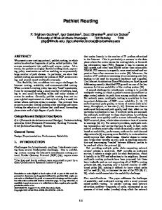
3.2.1 Neighbor discovery and topology construction The base station initializes neighbor discovery phase after the deployment of sensor nodes. Here each sensor node will broadcast N br DET packet once. At the end of neighbor discovery phase, each node has the information about their neighbors. After neighbor discovery phase, topology construction phase starts. In this phase, each node sends their neighbor information to the base station. For this, each node uses multicasting technique instead of flooding. The initiator node starts sending the neighbor information to base station through relay nodes as shown in Figure 1. The sender node chooses the relay node from N BR(x) and forwards the neighbor information to the base station as described in the Algorithm 1. Any sensor node will forward the N br IN F O
PROPOSED ROUTING PROTOCOL
Nbr_INFO
A
D
FO IN r_ Nb
Nbr_INFO
B
Nbr_INFO
C
Nbr_INFO
G
FO IN r_ b N
E
I FO N _I br N
FO N _I br N
FO IN r_ Nb
Nb r_ IN FO
Nbr_INFO
FO N _I br N
FO N _I br N
O NF r_I Nb
The proposed protocol adequately addresses the flaws presented in the existing schemes as mentioned in the Section 2. In randomly deployed sensor network, the sink node gathers neighbor information from the sensor nodes and creates a neighbor adjacency matrix. The sink node identifies the cluster head and selects the appropriate path. The sink sends the paths to the elected cluster heads. Each cluster head builds their cluster and sends the aggregated data to the sink. If routing path fails between cluster head and the sink, then sink selects another path for data transmission. The sink monitors each node’s residual energy and based on that it balances the load among the sensor nodes.
F
Nbr_INFO
H
3.1 Assumption The WSN is the combination of large sensor nodes and the communication link between them with in the radio range. The network can be presented as the graph G(V, E); here V = {v1 , v2 , ...vn } is the set of sensor nodes in the network. Each sensor node has the maximum communication range of radius R and E is the edge (link) between the node set (vi , vj ), where vi , vj ∈ V . It is the bidirectional link between node vi and vj . If the distance between two nodes is d(vi , vj ) ≤ R, then the communication link will be consid-
ACM SIGCOMM Computer Communication Review
Figure 1: Nodes send the Nbr INFO packet to the base station. packet only once for any source node to avoid the looping in the network. For doing this, each node maintains a received neighbor information list. Therefore, it reduces the traffic in the network and conserves the energy. The base station creates the neighbor adjacency matrix when it receives the
16
Volume 45, Number 2, April 2015
Algorithm 1
1. Any two cluster heads should not be neighbor to each other. 2. The residual energy Er of each cluster head should be greater than the threshold value. 3. Each cluster head should have at least k number of nodes as neighbor.
Neighbor Discovery and Topology Construction Data Structure for any sensor node x : N br(x): neighbor set of node x, initialized to φ. N brDET Sentx : set to true when the sensor node x sends N brDET packet, initialized to false. ReceivedN brIN F O(x): set of nodes by which node x received the N br IN F O packet, initialized to φ. node x receives following packet from node y:
Let CH = {Set of all cluster heads} and x ∈ CH N BR(x) = {Set of one hop neighbors of x} if (y ∈ N BR(x)) then y∈ / CH . This is the first condition for any node to be a cluster head end if
Nbr DET :< N br DET, Idy > if (y ∈ / N br(x)) then N br(x) N br(x) ∪ {y}; if (N brDET Sentx == f alse) then N brDET Sentx true; l rb(N br DET, Idx ); . Broadcast N br DET packet else Drop the packet; end if else Drop the packet; end if
Let Ethreshold = {Threshold energy of any node} and Er (x) = {Residual energy of node x} if (Er (x) ≥ Ethreshold ) then x ∈ CH . This is the second condition for any node to be a cluster head end if Let n is the alive nodes and m is the optimal number of cluster heads in the network Then, l = n−m . l is the number of nodes in a cluster m So that, N BR(x) ≥ l . This is the third condition for any node to be a cluster head
Nbr INFO :< N br IN F O, N br(y), Idy , Relay Id > if (Relay Id == Idx ) then if (y ∈ / ReceivedN brIN F O(x)) then ReceivedN brIN F O(x) ReceivedN brIN F O(x) ∪ {y}; if (Idx == IdBS ) then Update the neighbor adjacency matrix using N br(y); else l rf (N br IN F O, N br(y), Idy , Relay Id); . Forward the N br IN F O packet to the selected relay node end if else Drop the packet; end if else Drop the packet; end if
Selection of cluster head depends on two independent factors; one is the residual energy (Er ) and another is the degree of the node (D),i.e., the number of neighbor nodes. Let P r is the probability of any node x to become a cluster head then; P r(x) ∝ Er (x) × D(x)
After selecting the cluster head, the base station determines the path between the cluster head and the base station. The base station refers to the neighbor adjacency matrix and ensures the following selection criteria for routing path: 1. The residual energy of the sensor node in the path should be greater than the threshold value. 2. The total energy consumption of the routing path should be minimum.
N br IN F O from the sensor nodes. Neighbor adjacency matrix is shown in Table 1. It is a (n + 1) × (n + 1) matrix, where n is the number of nodes in the network and a base station. The neighbor adjacency matrix shows the network topology and connectivity of the nodes. Based on neighbor adjacency matrix, the base station selects the cluster heads and routing paths from each cluster head to the base station.
Let P = {Set of nodes in the path} and Er (x)= {Residual energy of any node x ∈ P } if (x ∈ P ) then Er (x) ≥ Ethreshold . This is the first condition for routing path selection end if
Table 1: Neighbor Adjacency Matrix BS A B C D E F G H I
BS 0 1 1 1 0 0 0 0 0 0
A 1 0 1 0 1 0 0 0 0 0
B 1 1 0 1 1 1 1 0 0 0
C 1 0 1 0 0 0 1 0 0 0
D 0 1 1 0 0 1 0 1 0 0
E 0 0 1 0 1 0 1 1 1 0
F 0 0 1 1 0 1 0 0 1 0
G 0 0 0 0 1 1 0 0 0 1
H 0 0 0 0 0 1 1 0 0 1
I 0 0 0 0 0 0 0 1 0 0
Let | P | = {number of nodes in the path} and Let P1 , P2 , P3 , ....Pj are the available paths from the cluster head to the base station. So, P = min1≤i≤j (| Pi |) . This is the second condition for routing path selection
To notify the senor nodes which have been chosen as a cluster head. The base station unicasts the intimation packet (i.e. CH IN T ) to the cluster heads using the selected path as illustrated in the Algorithm 2. The CH IN T packet follows the path and reaches the cluster head. The sensor nodes involved in the path make a reverse link towards the sink to relay the data from the cluster head. When the cluster head receives the CH IN T packet, it sends back an acknowledgment (ACK) packet to the base station. The ACK packet follows the same reverse path from where CH IN T packet came. The base station selects another path, if it does not receive the acknowledgment from the cluster head within a predefined time duration. The ACK packet generated by the cluster head is forwarded towards the base station through the selected path.
3.2.2 Cluster head selection and cluster formation After neighbor discovery and topology construction, formation of the cluster is started. Initially all nodes energy level are the same. After the formation of the neighbor adjacency matrix, the base station will compute and monitor the residual energy of each node. The base station chooses a certain number of cluster heads in the network using the following conditions:
ACM SIGCOMM Computer Communication Review
(1)
17
Volume 45, Number 2, April 2015
Algorithm 2
Algorithm 3
Cluster Head intimation Data Structure for any sensor node x : P AT H(x): set of sensor nodes involved in the path between the node x and the base station. RT able(x) : the routing table maintained by each relay node having two columns cluster head Id and next hop, initialized to φ.
Cluster Head selection and Cluster formation Data Structure for any sensor node x : RSSI(x): set of received signal strength of the sender nodes, initialized to φ. CHSelectedx : set to true when the sensor node x selected the cluster head, initialized to false. ChMbr(x): set of cluster members of any cluster head x, initialized to φ.
node x receives following packet from node y: CH INT :< CH IN T, Idy , P AT H(ch), Idch > if (Idch == Idx ) then l rf (ACK, Idx , next hop); . Forward the ACK packet to the base station else if (x ∈ P AT H(ch) && Idch ∈ / RT able(x)) then Update the RT able(x) by adding cluster head Id as Idch and next hop as Idy ; l rb(CH IN T, Idx , P AT H(ch), Idch ); . Broadcast CH IN T packet else Drop the packet; end if end if
node x receives following packet from node y: x∈ / CH and y ∈ CH
CH ADV :< CH ADV, Idy >; RSSI(x) ← RSSI(x) ∪ RSSIy ; After receiving all CH ADV , node x chooses the node with highest received signal strength as its cluster head. SelectedCHx ← true; l rf (CHJ OIN, Idx , Idch ); . Send the join request to the cluster head node x receives following packet from node y: x ∈ CH and y ∈ / CH
where
CH JOIN :< CH JOIN, Idy , Idch > if (Idx == Idch ) then ChMbr(x) ← ChMbr(x) ∪ y; After receiving all CH JOIN , node x sends the ChMbr(x) to the base station. Broadcast the time-slot schedule to the cluster members. else Drop the packet; end if
ACK :< ACK, Idy , next hop > if (next hop == Idx ) then if (Idx == IdBS ) then T ime out ← f alse; else Look up the RT able(x) and find the next hop of cluster head y; l rf (ACK, Idy , next hop); . Forward the ACK packet towards the base station end if else Drop the packet; end if
3.2.4 Re-clustering and rerouting
Afterwards, cluster head broadcasts the advertisement packet to form a cluster as illustrated in the Algorithm 3. Nodes receive more than one advertisement will choose the cluster head based on higher RSSI (Received Signal Strength Indication). After selecting the cluster head, nodes send the joining request as CH JOIN packet. Cluster head receives the CH JOIN packets from the interested nodes. After receiving all the joining requests, the cluster head sends the information of the cluster members to the base station. For reducing the congestion, the cluster head generates the time-slot schedule for cluster members based on TDMA [3] and sends to the cluster members. The TDMA time-slot is used for the collision-free communication between the cluster member and the cluster head.
The base station initiated the process of rerouting and re-clustering. To balance the load among the senor nodes, the base station monitors the residual energy of each senor node in the network. If any node falls below the threshold value, it initiates re-clustering or rerouting based upon the role of the node. If the node is the relay node of any path, the base station selects another available path to exclude that node. If the node is the cluster head, the base station selects another cluster head and corresponding path. This method increases the lifetime of the networks. The nodes having residual energy below the threshold, neither take part in routing nor become a cluster head, but only work as the cluster members.
4. SIMULATION RESULTS 4.1 Simulation Parameters The simulation of the proposed protocol and existing protocols are done using Castalia 3.2 simulator. It is a discreteevent simulator based on OMNeT++. The intensive set of simulation is performed based on the parameter illustrated in Table 2.
3.2.3 Data Transmission The cluster member transmits the generated data to the cluster head based on the given time slot and then changes the operational mode to sleep mode. The sensor node wakes up in the next time slot to transmit the data. In this way, the protocol serves the sensor node to conserve the energy. The cluster head aggregates the data and sends to the base station through the selected path. All intermediate relay nodes refer to the routing table for the next node to forward the data. When the data reaches the base station, an acknowledgment packet is sent back to the cluster head. If the cluster head does not receive the acknowledgment from the base station, it retransmits the data. The base station monitors the residual energy of each node in the network as it has the entire information of network topology. If base station finds residual energy of any node below the threshold value, it selects another available path for that cluster head.
ACM SIGCOMM Computer Communication Review
where
4.2 Results and Analysis Through the simulation, the proposed protocol performance has been analyzed and compared with the existing protocols such as FDCM [11] and PPCMP[4]. The performances of the protocols were compared based on the metrics such as control packet overhead, energy consumption, packet delivery ratio, end-to-end latency and network lifetime.
4.2.1 Average Control Packet Overhead It is the average energy consumption due to transmission and reception of control packets. The control packets are used in neighbor discovery, cluster formation, route
18
Volume 45, Number 2, April 2015
is less, and the sink selected the optimal path for the data transmission. The average energy consumption is less than the above two protocols.
Table 2: Simulation Parameters Value 1000 × 1000 meter 2 100 512 bytes 32 bytes 50 nJ/bit 10 pJ/bit/m2 0.0013 pJ/bit/m4 87 meters 5 nJ/bit 0.2 nJ/sec 500 sec TMAC
0.6
Average Energy Consumption(J)
Parameter Name Network area Number of sensor nodes Data packet size Control packet size Eelec εf s εmp d0 Eproc Elow Simulation time MAC protocol
FDCM PPCMP 0.5
0.4
0.3
0.2
50
200
250
300
350
400
4.2.3 Packet Delivery Ratio (Throughput) It is the ratio of successfully received data packets at the sink and the total number of data packets sent by the source. This parameter also shows the data transmission reliability. The packet delivery ratio of each protocol is depicted in Figure 4. PPCMP uses the node disjoint multipath routing, which increases the reliability hence throughput also increases. The FDCM does not take any precaution if the path fails between the source and the sink. In fact, it chooses the neighbor cluster head from the available list without knowing the current residual energy. The reliability of the protocol gets decreased, hence the throughput also decreases. In the proposed scheme, path is selected by the sink. The sink monitors the residual energy of each node in the path. When it finds any node’s residual energy below the threshold, it selects another path for data transmission. Hence, the data loss is negligible.
Proposed FDCM PPCMP
100
0.3
Packet delivery ratio(%)
Average Control Packets Overhead (J)
150
Figure 3: Average Energy Consumption
0.4
0.2
0.1
50
100
Simulation time (s)
construction, maintenance process and so on. The control packet overload by the protocol is shown in Figure 2. For multipath construction, branch aware flooding is used to flood the control packet over the network in PPCMP. This is the major cause which increases the control packet overhead, although it consumed less control overhead for cluster head selection. Further, the multipath construction takes place each time when the new node becomes the source node. This is an overhead to the protocol. In the FDCM, the control overhead is less than PPCMP but more than the proposed protocol. In the cluster formation phase the exchange of test request and reply for testing faulty node is an overhead. In multipath construction the control packet broadcasts in the increased range of 2R. It consumes more energy. Whereas the proposed scheme neither uses flooding nor involves the whole network to select the cluster head and multipath. The sink selects the cluster heads and the paths between the cluster heads and the sink. So the control overhead is very less as compare to PPCMP and FDCM. 0.5
Proposed
100
150
200
250
300
350
400
Simulation time (s)
80
60
40
20
Figure 2: Control Packet Overhead
Proposed FDCM PPCMP
30
40
50
60
70
80
90
100
Number of nodes
4.2.2 Average Energy Consumption Figure 4: Packet Delivery Ratio
This is the average amount of energy consumed at each node due to transmission and reception of control and data packets. The performance result is illustrated in Figure 3. Although PPCMP uses the optimal path to transmit the data. Due to increased control packet overhead, the average energy consumption is more. In FDCM, the control packet overhead is more, and the aggregated data transmitted through the cluster heads with the range of 2R. It increases the overall energy consumption as it takes twice the power to transmit the data as compared to the other protocol. Whereas in the proposed protocol, the conrtol overhead
ACM SIGCOMM Computer Communication Review
4.2.4 End-to-End Latency It is calculated as the average time between generation of the data packet from the source and the successful reception at the sink. In the PPCMP, each candidate cluster head node has to wait for a period of time to become the cluster head. In addition to that, for each new event when the source node changes, the protocol has to create the multipath for the
19
Volume 45, Number 2, April 2015
fresh source node. It increases the overall delay. In the FDCM, due to available neighbor cluster head list the endto-end delay is less. In a situation where the network has to choose a new cluster head, the selection process starts from the beginning, which increases the delay. In the proposed scheme, the alternative paths are available. Hence, the endto-end delay is less. The results in Figure 5 shows that the proposed scheme is faster than the PPCMP and marginally better than the FDCM.
Data delivery latency (s)
0.5 0.45
tion results show that the proposed protocol outperformed the existing protocols FDCM and PPCMP.
6. REFERENCES [1] I. T. Almalkawi, M. G. Zapata, and J. N. Al-Karaki. A cross-layer-based clusteredmultipath routing with qos-aware scheduling forwirelessmultimedia sensor networks. International Journal of Distributed Sensor Networks, 2012:1–11, 2012. [2] T. Bagheri and A. Ghaffari. Recm: Reliable and energy effective clustering based multi-path routing algorithm for wireless sensor networks. In Proceedings of IEEE World Congress on Information and Communication Technologies (WICT’11), pages 1340–1345, Dec 2011. [3] V. Cionca, T. Newe, and V. Dadarlat. Tdma protocol requirements for wireless sensor networks. In Proceedings of the IEEE Second International Conference on Sensor Technologies and Applications, pages 30–35, Aug 2008. [4] R.-C. Jin, T. Gao, J.-Y. Song, J.-Y. Zou, and L.-D. Wang. Passive cluster-based multipath routing protocol for wireless sensor networks. Wireless Networks, 19(8):1851–1866, Nov 2013. [5] Y.-B. Ko, J.-M. Choi, and J.-H. Kim. A new directional flooding protocol for wireless sensor networks. In Proceedings of International Conference INCOIN 2004, Lecture Notes in Computer Science, pages 93–102, Feb 2004. [6] W. Liu, S. Zhang, and J. Fan1. A diagnosis-based clustering andmultipath routing protocol forwireless sensor networks. International Journal of Distributed Sensor Networks, 2012:1–11, 2012. [7] M. R. Mazaheri, B. Homayounfar, and S. M. Mazinani. Qos based and energy aware multi-path hierarchical routing algorithm in wsns. Wireless Sensor Network, 4:31–39, 2012. [8] S. Mueller, R. P. Tsang, and D. Ghosal. An efficient n-to-1 multipath routing protocol in wireless sensor networks. In Proceedings of IEEE International Conference on Mobile Adhoc and Sensor Systems Conference, pages 672–679, Nov 2005. [9] T. N. Quynh, T. T. Vinh, and M. B. T. Quynh. Multipath routing for cluster-based and event-based protocols in wireless sensor networks. In Proceedings of the Third ACM Symposium on Information and Communication Technology SoICT’12, pages 172–179, 2012. [10] Y.-H. Wang, C.-H. Tsai, and H.-J. Mao. Hmrp: Hierarchy-based multipath routing protocol for wireless sensor networks. Tamkang Journal of Science and Engineering, 9(6):255–264, 2006. [11] J. Yang, M. Xu, W. Zhao, and B. Xu. A multipath routing protocol based on clustering and ant colony optimization for wireless sensor networks. MDPI Sensors, 10:4521–4540, May 2010. [12] M. S. Zaman and G. R. Murthy. Clustered and leveled disjoint multipath routing algorithm for wireless sensor networks. In Proceedings of the First IEEE Asian Himalayas International Conference on Internet AH-ICI’09, pages 1–5, Nov 2009.
Proposed FDCM PPCMP
0.4 0.35 0.3 0.25 0.2
30
40
50
60
70
80
90
100
Number of nodes
Figure 5: End to End Latency
4.2.5 Network Lifetime It is the time period of the network when the first node dies. In the network, the control packets are exchanged for neighbor maintenance, cluster heads selection, cluster formation, route discovery, establishment and maintenance. It reflects the routing overhead and directly affects the lifetime of the network. It is clearly shown in Figure 6 that, the network lifetime of the proposed scheme is greater than the FDCM and PPCMP. The reason behind this is, it consumes few control packets and balances the load among the sensor nodes.
Number of nodes alive
100
80
60
40 Proposed FDCM PPCMP 50
100
150
200
250
300
350
400
Simulation time(s)
Figure 6: Network Lifetime
5.
CONCLUSION
This paper proposed an energy efficient routing scheme using the clustering and multipath technique. The work loads of the sensor nodes are alleviated by giving more responsibility to the base station. The multipath gives more reliability to the network, and it increases the throughput and decreases latency. In addition to that, cluster based data collection reduces the traffic and energy consumption and also increases the lifetime of the network. The simula-
ACM SIGCOMM Computer Communication Review
20
Volume 45, Number 2, April 2015