VAWKUM Transactions on Computer Sciences http://vfast.org/index.php/VTCS@ 2015 ISSN: 2308-8168 Volume 6, Number 1, January-February 2015
pp-21-30
CODE SHIFTED REFERENCE BASED COOPERATIVE USING MULTIPLE RELAYS IN ULTRA WIDE BAND COMMUNICATION SYSTEM PIR MEHER ALI SHAH1, LATIF JAN1,MUHAMMAD AMIN2,MANSOOR 2 QADIR2, MUHAMMAD WAQAS1, GHASSAN HUSNAIN ,SALMAN KHAN3 1
Department of Electrical Engineering, Iqra National University(INU)Peshawar 2 Department of Computer Science, Iqra National University(INU)Peshawar 3 Department of Computer Science, Abdul Wali Khan University Mardan
[email protected],
[email protected],
[email protected],
[email protected],
[email protected],
[email protected],
[email protected]
Received May 2014 ABSTRACT. The technology of Ultra Wide band now a days is quite demanding due to the characteristics like its simple architecture , low power consumption and cost reliability but still it faces some deficiencies in term of its design to achieve low complexity and low cost. UWB systems experience problems while using digital signal processing technology and require high sampling frequencies. In this paper, the performance of UWB system in the cooperative communication environment is evaluated in terms of its Bit Error Rate for different number of relays and different average distances from source to destination node. The simulations are performed for both line of sight (LOS) and non-line of sight (NLOS) environment. Results from simulation shows that the performance of the system decreases by increasing average source to destination distance. The simulation results also shows that the system performs better in LOS channel environment as compared to NLOS channel environment. In the end results, it shows that the performance of the system increases by increasing the number of relay nodes to adequately large number. Keywords: Ultra Wide Band; Line Of Sight; Non-Line Of Sight; Code Shifted Reference. 1. INTRODUCTION: Impulse Radio UWB (IR-UWB) is capable of high speed information transmission, immense multipath resolution, low power expenditure and is highly cost efficient [1]. These features have made IR-UWB very popular in wireless communication. Federal Commission of communication (FCC) has set a standard according to which the average transmitted power of the UWB signal is pretty low [2]. The power of the received signal decreases after its transmission through multipath fading channel, which makes it difficult to detect and demodulate the UWB signals [1]. Therefore, cooperative communication technique has been introduced in UWB system for efficiently increasing the power at the receiver side and upgrades the performance of the UWB system [3]. Here, based on IEEE 802.15.4a channel model, we have implemented cooperative communication with CSR-UWB system using decode and forward (DF) relay method, and the performance of its BER in different scenarios which will be discussed later in the result part. 2. COOPERATIVE COMMUNICATION: The benefits of multiple-input multiple-output (MIMO) systems have been so largely recognized that certain transmit diversity techniques have become a very
21
important part of wireless standards [4]. However, transmit diversity might not be a practical scheme for other scenarios, even though it is highly beneficial for cellular base stations [5]. Wireless agents might not be capable of supporting multiple transmit antennas because of certain factors like cost, size and limitations of hardware [5]. This is the reason why cooperative communication was introduced. Cooperative communication allows single-antenna mobiles to possess some of the advantages of MIMO communication systems [6]. The basic concept of cooperative communication is that single antenna systems within a multiuser set-up can share their antennas in such a style that a virtual MIMO system is created [7]. It has been observed that channels in a wireless scenario are subjected to fading which means that the signal strength can decay noticeably during the course of transmission [8]. Diversity can be generated by transmitting independent copies of the signal, and this can efficiently reduce the injurious effects of fading. Particularly, by the transmission of signals from different locations, spatial diversity is generated. This gives different independent faded copies of the signal at the receiver [9]. This diversity can be generated in a new and exciting fashion by cooperative communication. The idea of cooperative communication is to promote the broadcast feature of wireless communication networks, in which the neighboring nodes “overhear” the signal from the source and then relay the information to the destination [10]. In Fig. 2.1, A third-party terminal acts as a relay by receiving the signals from the source and forwarding the overheard information to the destination to expand the capacity and upgrade the reliability of the direct communication. The end-to-end transmission is separated into two different phases in time domain which are: broadcasting and relaying [11]. In the broadcasting stage, all receiving terminals (i.e. relays and destination) operate in the same channel (i.e. time or frequency). In the relaying stage, the transmitting terminals (relay nodes) may work in separate channels to dodge co-channel interference [11].
Figure 2.1: Basic cooperative communication comprising a single relay 3. COOPERATIVE COMMUNICTION PROTOCOLS: PROCESSING MODES OF RELAYS: The basic concept of cooperative relaying is that the signal is transmitted by the source to both the relay and destination [12]. The relay receives the same signal from the source and then retransmits it to the destination. The destination merges the received signal from both the relay and source to boost reliability. This whole process can be carried out by various methods of relaying protocols which are discussed in the following subsections. 3.1 Decode-and-Forward (DF): In decode-and-forward scheme, using regenerative method, relay node is going to decode the incoming signal from the source, and then re-encodes it prior to forwarding it to the destination [12]. Possibly wrongly decoded information at the relay can considerably lower the performance of the system because of error propagation [13]. Therefore, it is supposed that, relays helps direct communication only if the source signal has been detected correctly. It is assumed that cyclic redundancy check (CRC) code to be capable of perfectly decoding the information. Such a relay using the approach of CRC can be called as adaptive DF [14]. Nevertheless, this approach is not always practical because the relay is sometimes not capable of correctly detecting the signal from the source. Hence, another approach called fixed DF mode is introduced where the relay always forwards the decoded information to the destination
22
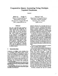
irrespective of the received signal quality. When the quality of the channel between the source and relay is very fine, the relay is capable of decoding very quickly and correctly. 3.2 Amplify-and-Forward (AF): In amplify-and-forward scheme, using non-regenerative method, the relay node is going to amplify the signal from the source without decoding, and then puts forward to the destination [15]. The noisy form of the signal from the source is multiplied by the relay with the amplifying gain with a constraint (e.g. power constraint) and the resulting version of the signal is transmitted to the destination. The complexity of hardware is lower in AF than DF as the decoding section is excluded in AF. Even though the noise is also amplified along with the signal, the destination can still make a better detection of the information as it receives two independent faded versions of the signal [16]. AF relay can be further divided into two subcategories. If the relay has complete awareness about the channel state information (CSI), the amplify gain can be changed [7]. Such a relay is called variable-gain AF relay or CSI-assisted AF relay. Whereas, if the relay needs only the statistical characteristics of the channel in between source and relay, the relay is called fixed gain AF relay or semi-blind AF relay. The latter has less complexity, but lacks behind from the former with respect to performance regarding error-rate. 3.3 Compress-and-Forward (CF): Compress-and-Forward is another technique of relaying which does not require decoding in the relay. In Compress-and-Forward relaying method, the signal received from the source is quantized and compressed by the relay with the aid of Wyner-Ziv lossy source coding [17]. The compressed version of the signal is then transmitted to the destination by the relay. The received information from the source and the quantized and compressed form of that information from the relay is merged by the destination. CF performs better than DF on the basis of achievable rate when the relay is near to the destination and vice versa [17]. 3.3.1 Estimate-and-Forward (EF): Estimate-and-Forward is also another relaying method where decoding is not needed in the relay. In Estimate-and-Forward, an analog estimate of the signal received from the source is forwarded by the relay to the destination [18]. This estimation is done by entropy constrained scalar quantization of the signal received from the source or with the help of an unconstrained minimum mean square error (MMSE) technique. DF performs better than EF with regards to achievable rate when the relay is far from the destination and vice versa [18]. 3.4 CODED COOPERATION: Coded cooperation is distinct from other relaying techniques because in this scheme, the channel coding is integrated into cooperation [7]. The data (codeword) of every user is divided into two parts. At first, every user transfers the former segment of its own codeword and tries to decode the other segment of its corresponding communication partner [19]. If the information is successfully decoded as verified by the Cyclic Redundancy Check (CRC) code, the user creates the left over portion of its partner’s codeword and sends it to the destination. Else, the user sends the left over portion of its own codeword. The user and its corresponding communication partner should work in an environment of orthogonal channels. In coded cooperation, various channel coding techniques can be assigned [19]. 3.5 COOPERATIVE UWB SYSTEM MODEL: Cooperative Communication in UWB systems generally follows ad-hoc network structure and is used to reduce the system complexity [20]. In such structure, every node perform a special role which can either be a Source node (S), Destination node (D) or Relay node (R). However among these, a node can only play a single role in such process of communication. A cooperative communication in UWB systems also consist of Source node, Destination node and some Relay nodes. Fig 2.2 shows a communication model for cooperative UWB system where “M” represents the number of relay nodes. In cooperative UWB system model, process of communication is performed in the following three stages [21]: i. At first, the source node transmits pilot symbol to all of the relays. At this phase, because of the obstructions in the links in between the source node and the relay nodes, the links aren’t confirmed. ii. From among all the relay nodes, only the relay with the best bit error rate (BER) performance is chosen as the relay of that communication process. For the purpose of minimizing the power consumption of the network, only a single relay node is selected for each communication process. iii. The communication in between the source node and the destination node takes place via the selected relay node. In Fig.2.2, the channel fading of the source to relay link is represented by hi(t), where i=1, 2, …, M. The
23
number of relays is represented by “M”. The channel fading can be calculated once the pilot symbols are received by the relays. The pilot symbols along with the achieved signal-to-noise ratio (SNR) are then retransmitted to the destination node from every relay node in separate time slots [21]. The pilot symbols from separate relay nodes are demodulated at the receiving side. At this point, the channel fading of the relay to destination link is evaluated. In Fig.2.2, the channel fading of the source to relay link is represented by g i(t), where i=1, 2, …, M.
R h1(t) h2(t)
S
R2
1
hM-1(t) hM(t)
g1(t) g2(t)
gM-1(t)
RM-1
selection of only a single relay
D
gM(t)
RM Figure 2.2: Cooperative UWB system model
After the selection of the relay node with the best BER performance, the source node transmits the data signal to the destination node via this path [21]. Generally, RAKE receiver is implemented for the collection of multipath energy, and better performance is achieved at the expense of the complexity of hardware [20]. Generally in order to improve the system performance, the desired number of correlators is more than 10. Nevertheless, that large number of correlators simply enhances the complexity of the system extensively [21]. Because a UWB system requires to be simple and low in cost, RAKE receiver is hardly employed in the adoption of UWB systems. Energy detection receivers are capable of decreasing the complexity of the system [9]. However, in that case, UWB system’s performance is degraded. Hence, we have used Code-shifted reference (TR) receiver as it is capable of balancing system complexity with system performance. If amplify-and-forward (AF) cooperative communication protocol is implemented, the multipath component at the source-relay link is amplified and forwarded towards the destination [15]. Several multipath components are resulted after passing via the dense multipath channel in between the relay nodes and the destination node. These multipath components interfere with each other and decrease the SNR at the destination node [16]. Therefore, taking the dense multipath feature of UWB channel under consideration, we have implemented decode-and-forward (DF) protocol in our cooperative UWB system model to transmit the data from the source node to the destination node through the relay nodes. This decreases the complexity of the system as well as avoids the distortion of waveform that results from multipath expansion. 3.6 RELAY POSTIONING: It has been said that the UWB system gives better BER performance when the relay nodes are positioned in between the source and destination nodes [7]. But it is important to know the particular position of a relay in between the source node and the destination node that gives the best BER performance [9]. By the term “position”, here we can relate to the distance at which a relay is located from the source and destination. Distance is an important factor in signal transmission. The signal quality decreases with the increase in distance because of factors like path-loss, power-loss, noise and interference. We have considered Dxi as the distance between the source node and the relay node, and, Dyi as the distance between the relay node and the destination node, where i=1,2,…,M. The number of relays is represented as “M”. Let, D be the distance between the source node and the relay node.
24
Fig. 3.1 shows the BER performance of the UWB system as a function of Eb/N0 under the IEEE 802.15.4a office LOS channel environment with the relay node at different distances from the source and destination. The source node and the destination node are kept at a distance (D) of 10 meters. It is assumed that the relays are kept at certain points over a straight line in between the source node and the relay node, so as to keep the overall transmission distance constant (10m) for all cases to ease performance comparison, i.e. D = Dxi + Dyi. Simulations are done for the BER performances of 5 relays which are kept at a distance (Dxi) of 2m, 4m, 5m, 7m and 9m from the source node. Thus, the corresponding distances (Dyi) of these relays from the destination node are 8m, 6m, 5m and 1m respectively. It can be noted that the third relay is at an equal distance from the source node and destination node, ie. Dxi = Dyi = 5m. BER performance for a case with no relay is also simulated, i.e. the direct transmission of the data signal from the source node to the destination node without any relay. The fame duration the CSR-UWB is taken as Tf = 60 ns with the number of frames as Nf = 8. 0
10
-1
BER
10
-2
10
Dxi=2, Dyi=8 Dxi=4, Dyi=6 Dxi=5, Dyi=5 Dxi=7, Dyi=3 Dxi=9, Dyi=1 No Relay
-3
10
-4
10
18
18.5
19
19.5
20
Eb/No (dB)
20.5
21
21.5
22
Figure 3.1: BER performances with relays at different positions The simulation result clearly shows that the CSR-UWB system model performs better with the presence of relay than with the absence of relay. It can be observed that the BER performance of the cooperative UWB system model increases as the relay gets closer to the centre point in between the source node and the destination node. The cooperative CSR-UWB system model gives the best BER when Dxi = Dyi = 5m at D =10m. Thus, we can say that the cooperative CSR-UWB system has the minimum BER when the relay is place at the equal distance from the source node and the destination node. 4. PERFORMANCE COMPARISON OF COOPERATIVE CSR-UWB SYSTEMS UNDER DIFFERENT CHANNELS: In the earlier section, it has been assumed that the relay is positioned just anywhere over the straight line in between the source node and the destination node for performance comparison purposes. However, in a practical situation, the relays may not exactly placed between the source and destination nodes over the straight line. Therefore, we can assume the angle made by that line with the line between the source node and relay node as , that is evenly distributed from 0 to [21]. We have come to know from the previous section that the cooperative CSR-UWB system has the best BER performance when the relay is equidistant from the source node and the destination node. So, let us suppose that Di= Dxi = Dyi (where i=1,2,…,M) is the distance from the source node to relay node as well as the distance from the relay node to destination node. Hence, for a given value of Di , the average distance from the source node to destination node can be specified as the following [21]:
25
Di
1 4 Di Di2 Di2 2 Di2 cos d 0
(1)
We evaluated the performances of cooperative CSR-UWB system for different number of relays, in LOS (Line of Sight) and NLOS (Non-Line of Sight) environments and different average distance between source node and destination node. We have separated the simulations into two sections. The first section is concerned with the BER performances of cooperative CSR-UWB system for the number of relays M=5 and the second with number of relays M=10. We have taken the CM3 and CM4 with 100 channels from IEEE 802.15.4a channel model in our simulations. CM3 channels represent the LOS (Line of Sight) channels and CM4 channels represent the NLOS (Non-Line of Sight) channels. We have assumed two different values for the average distance between the source and the destination which are Di = 4m and 7m. The frame duration of CSR-UWB is taken as Tf = 60ns with the number of frames as Nf = 8. a. Simulation results with 5 relays: The simulation of the cooperative CSR-UWB system with 5 relays is performed under LOS and NLOS channel environments with 4m and 7m average distance between source and destination. Evaluation of the performances is given in the following subsections. b. 4m(LOS) vs. 7m (LOS) with 5 relays: First, the performance of the system is compared between scenarios of average source-destination distance 4m and 7m. Both simulations are performed with an IEEE 802.15.4a LOS channel CM3. From Fig. 4.1, we can observe that, in LOS channel environment, at a BER requirement of 10-3, the cooperative CSR-UWB system with average source-to-destination distance of 4m outperforms the one with average source-to-destination distance of 7m by 4dB. 0
10
-1
Bit Error Rate
10
-2
10
LOS (4m) LOS (7m) -3
10
18
20
22
24
26
28
Eb/No(dB)
30
32
34
36
Figure 4.1: System BER performance at LOS (4m) and LOS (7m) for M=5 c. 4m (LOS) and 7m (LOS) vs. 4m (NLOS) with 5 relays: The system performance with the average distance of 4m between source-to-destination in an IEEE 802.15.4a NLOS channel CM4 is compared with the ones with 4m and 7m source-destination distance in an IEEE 802.15.4a LOS channel CM3. We can observe in Fig. 4.2 that, for the same distance of 4m, at a BER requirement of 10-3, the performance of the system in LOS channel environment is 9dB better than that in NLOS channel environment.
26
0
10
-1
Bit Error Rate
10
-2
10
LOS (4m) LOS (7m) NLOS (4m) -3
10
18
20
22
24
26
28
30
Eb/No(dB)
32
34
36
38
40
Figure 4.2: System BER performance at LOS (4m), LOS (7m) and NLOS (4m) for M=5 d. 4m (LOS), 7m (LOS) and 4m (NLOS) vs. 7m (NLOS) with 5 relays: Simulations are done to compare the peak performance of the proposed system of an average source-destination distance using 4m and 7m for both LOS and NLOS channel environments. IEEE 802.15.4a CM3 channels are used for LOS environment and IEEE 802.15.4a CM4 channels are used for NLOS environment. Fig. 4.3 shows that the system BER performance is worst at 7m average source-to-destination distance for NLOS channel environment. 0
10
-1
BER
10
-2
10
LOS (4m) LOS (7m) NLOS (4m) NLOS (7m) -3
10
18
20
22
24
26
28
30
Eb/No(dB)
32
34
36
38
40
Figure 4.3: System BER performance at LOS (4m), LOS (7m), NLOS (4m) and NLOS (7m) for M=5 5. SIMULATION RESULTS WITH 10 RELAYS: The simulation of the cooperative CSR-UWB system with 10 relays is done under LOS and NLOS channel environments with average distance of 4m and 7m between source node and destination node. Assessment of the performances is given in the following subsections.
27
a. 4m (LOS) vs. 7m (LOS) with 10 relays: The performance of the system is compared between scenarios of average source-to-destination distance 4m and 7m. Both simulations are performed with an IEEE 802.15.4a LOS channel CM3. We can observe that, Fig. 5.1 also shows similar results as in Fig.4.1. Here also, at 10-3 BER requirement under LOS channel environment, the BER performance of the cooperative CSR-UWB system with average source-to-destination distance of 7m is 4dB less than the one with average source-to-destination distance of 4m.
0
10
-1
Bit Error Rate
10
-2
10
LOS (4m) LOS (7m) -3
10
18
20
22
24
26
28
Eb/No(dB)
30
32
Figure 5.1: System BER performance at LOS (4m) and LOS (7m) for M=10 b. 4m (LOS) and 7m (LOS) vs. 4m (NLOS) with 10 relays: The system performance with 4m average source-to-destination distance in an IEEE 802.15.4a NLOS channel CM4 is compared with the ones with 4m and 7m source-destination distance in an IEEE 802.15.4a LOS channel CM3 with 10 relays. We can observe in Fig. 5.2 that, at the same average source-to-destination distance of 4m, the cooperative CSR-UWB system under LOS channel environment outperforms the one under NLOS channel environment by about 9dB at a BER requirement of 10-3. 0
10
-1
Bit Error Rate
10
-2
10
LOS (4m) LOS (7m) NLOS (4m) -3
10
18
20
22
24
26
28
Eb/No(dB)
28
30
32
34
36
Figure 5.2: System BER performance at LOS (4m), LOS (7m) and NLOS (4m) for M=10 c. 4m (LOS), 7m (LOS) and 4m (NLOS) vs. 7m (NLOS) with 10 relays: Simulations are done to compare the system performance with average source-to-destination distance 4m and 7m for both LOS and NLOS channel environments with 10 relays. IEEE 802.15.4a CM3 channels are used for LOS environment and IEEE 802.15.4a CM4 channels are used for NLOS environment. Fig. 5.3 shows that the channel with average source-to-destination distance of 7m under LOS channel environment gives the poorest performance. 0
10
-1
BER
10
-2
10
LOS (4m) LOS (7m) NLOS (4m) NLOS (7m) -3
10
18
20
22
24
26
28
30
Eb/No(dB)
32
34
36
38
40
Figure 5.3: System BER performance at LOS (4m), LOS (7m), NLOS (4m) and NLOS (7m) for M=5 By the comparison of Fig. 4.3 and Fig. 5.3, we can observe that the cooperative CSR-UWB system with 10 relays outperforms the cooperative CSR-UWB system with 5 relays by about 4dB under a BER requirement of 10-3 for both LOS and NLOS channel environments. This is because more number of relay nodes opens greater possibilities of getting the relay node with the highest BER performance. Those relay nodes which are placed nearer to each other or placed in the straight line between the source node and destination node gives the best system BER performance. Nevertheless, at a point when the number of relays (M) becomes adequately huge, adding more number of relay nodes does not make the system BER Performance any better. 6. CONCLUSION: In this paper, a Code Shifted Reference impulse-based Cooperative UWB Communication System has been proposed. The BER performance comparison of the proposed cooperative CSR-UWB system has been analyzed for different number of relays under different channel environments using IEEE 802.15.4a channel model. The simulation results show that, under a LOS channel at a BER requirement of 10-3, the performance of the cooperative CSR-UWB system with 4m average source-todestination distance is approximately 4dB better in SNR than the one with 7m. This is extracted from the results that the overall performance is degraded if the distance of source-to-destination increases. We can also see that with the same average-to-destination distance of 4m, the performance of the system under a LOS channel environment is about 9dB better than that under a NLOS channel environment. Hence, we can conclude from the result that performance of the system improves under a LOS channel environment as compared to NLOS channel. It can also be observed that the system with 10 relays outperforms the system with 5 relays. This means that by increasing the number of relays to adequately large number, the performance of Code Shifted Reference impulse-based Cooperative UWB Communication System Improves.
29
REFERENCE
[1] [2] [3] [4] [5] [6] [7] [8] [9] [10] [11] [12] [13] [14] [15] [16] [17] [18] [19] [20] [21]
Fernandes, J. R. ,Wentzloff ,D.(2010). Recent Advantages in IR-UWB Transceivers: An Overview. IEEE International Symposium on Circuits and Systems (ISCAS), pp. 3824-3287. Gabriella,M. ,Benedetto,D. ,Giancola,G.(2004) .Understanding ultra wide band radio fundamentals. Prentice Hall, New Jersey. Shirazi, G. N, Kong,P. Y, Tham,C. K.(2008). A cooperative retransmission scheme for IR-UWB networks. IEEE international conference in Ultra-Wideband, Hannover.( vol.2, pp.207-210). Wang, L., Shanbhag,N. R.(2003). Low Power MIMO Signal Processing. IEEE Transaction on Very Large Scale Integration (VLSI) Systems.( vol. 11, pp. 434-445). Zhu, S., Leung, K.K.(2007).Cooperative orthogonal MIMO relaying for UWB Ad-Hoc networks. In IEEE Globecom, New Orleans, pp. 5175-5179. Biglieri, E., Calder bank, R., Constantinides, A., Goldsmith, A., Paulraj, A., Poor, H. V. (2007). MIMO wireless communications. Cambridge: Cambridge University Press. Nosratinia, A., Hunter, T.E., Hedayat, A. (2004). Cooperative Communication in Wireless Networks. IEEE Communication Magazine. ( vol. 42, pp. 74-80 ). Yu, G., Zhang,Z., Chen,Y., Qiu,P. (2007). Adaptive Power Allocation For Cooperative Relaying System in Fading Wireless Channel. In International Conference on Wireless Communications, Networking and Mobile Computing, WiCOM 2007, pp. 1116-1119. Laneman, J. N., Tse, D.N.C., Wornell, G.W.(2004) .Cooperative Diversity in Wireless Networks: Efficient Protocols and Outafe behavior. IEEE Transaction on Information Theory,( vol. 50, pp. 3062-3080). Gao, Y., Ge, J., Han, C. (2011). Performance Analysis of Differential Modulation and Relay Selection with Detect and Forward Cooperative Relaying. IEEE Communications Letters, (vol. 15, pp. 323-325). Frank, H. P., Fitzek, Katz, M.D. (2006) .Cooperation in Wireless Networks: Principles and Applications Netherlands: Springer. Yi, Z., Kim, M. (2007) .Decode and Forward Cooperative Networks with Relay Selection. In 66th IEEE Vehicular Technology Conference VTC-2007, pp. 1167-1171. Lin, W., Wu, G., Zhang, L., Li, S.(2008). Performance Analysis of Cooperative Networks with Random Decode and Forward Relaying. In 10th IEEE International Conference on High Performance Computing and Communication- HPCC 2008, pp. 526-531. Ikki, S. S., Ahmed, M. H.(2010) .Performance Analysis of Adaptive Decode and Forward Cooperative Diversity Networks with Best-Relay Selection, In IEEE Transactions on Communications,(vol. 58, pp. 68-72). Qiuna, Y., Wu, Y. D., He, Y. (2010). Cooperative Diversity of Wireless Networks with Multiple Amplify and Forward Relays, In 2010 International Conference on Communications and Mobile Computing (CMC), pp. 207-212. Jose, J., Ying, L., Vishwanath, S.(2009). On the Stability Region of Amplify and Forward Cooperative Relay Networks, In 2009 IEEE Information Theory Workshop, pp. 620-624. Jing, J., Thompson, J. S., Grant, P. M.(2010). Design and Analysis of Compress and Forward Cooperation in a Virtual MIMO Detection System, In 2010 IEEE GLOBECOM Workshops (GC Wkshps), pp. 126-130. Chakrabarti, A., Baynast, A.de., Sabharwal, A., Aazhang, B.(2006). Half-Duplex Estimate and Forward Relaying: Bounds and Code Design, In 2006 IEEE International Symposium on Information Theory, pp. 1239-1243. Hunter, T. E., Nosratinia, A.(2006). Diversity Through Coded Cooperation, In IEEE Transactions on Wireless Communications, (Vol. 5, pp. 283-289). Vardhe, K., Reynolds, D., Woerner, B.(2010). Power Allocation and Relay Selection in Cooperative Wireless Networks, In Military Communication Conference-MILCOM 2010,pp. 2108-2112. Shen, Q. H., Wu, X., Lin, D., Qiu, X.(2010). Performance Analysis of Cooperative Ultra-wideband Communication System, In 2010 International Conference on Communication and Mobile Computing (CMC), pp. 217-220.
30