well as the hardware implementation specs. Comparison with existing ..... S1 = s13α3 + s12α2 + s11α + s10, S3 = s33α3 + s32α2 + s31α +s30, S5 = s53α3 ...
BCH Code Based Multiple Bit Error Correction in Finite Field Multiplier Circuits M. Poolakkaparambil1 , J. Mathew2 , A. M. Jabir1 , Dhiraj K. Pradhan2 and S. P. Mohanty3 1 Dept. of Comp. Sci. & Electronics, Oxford Brookes University, UK 2 Department of Computer Science, University of Bristol, UK 3 Department of Comp. Sci. & Engineering, University of North Texas Abstract— This paper presents a design methodology for multiple bit error detection and correction in Galois field arithmetic circuits such as the bit parallel polynomial basis (PB) multipliers over GF(2m ). These multipliers are crucial in most of the cryptographic hardware designs and hence it is essential to ensure that they are not vulnerable to security threats. Security threats arising from injected soft (transient) faults into a cryptographic circuit can expose the secret information, e.g. the secret key, to an attacker. To prevent such soft or transient fault related attacks, we consider fault tolerance as a method of mitigation. Most of the current fault tolerant schemes are only multiple bit error detectable but not multiple bit error correctable. Keeping this in view, we present a multiple bit error correction scheme based on the BCH codes, with an efficient bit-parallel Chien search module. This paper details the design procedure as well as the hardware implementation specs. Comparison with existing methods demonstrate improved area, and reduced delay performances.
I. I NTRODUCTION Online error detection and correction has received much attention in recent years as a candidate for attack tolerant cryptographic hardware design and to certain extent fault tolerance as well [1]. With low operating voltage levels and low noise margins, digital designs are often vulnerable to various faults [2]. In present day communication devices, cryptographic hardware is an inevitable part. The cryptographic hardware often needs to store some information hidden in order to ensure high degree of information security. The Faults resulting in incorrect output are mainly due to naturally occurring faults or due to malicious attacks. The former can be detected with various testing techniques, whereas the latter cannot be detected with the testing schemes presently available. Clearly, this can result in catastrophe, if undetected [8]. Attacks against such cryptography hardware are often classified into two categories: invasive and non-invasive. The invasive attacks are based on reverse engineering and hence require costly equipment. The non-invasive method, on the other hand, exploits the implementation weakness of the device and is also known as the side channel attacks [3]. It is also noted that, hacking of information within the chip is possible by introducing hardware Trojans within the process variation allowance of the chip [4]. In these types of attacks, the attacker may try to acquire the hidden information by injecting random events, e.g. through transient faults, into the hardware [7]. To keep our information hidden, we need to mask these injected faults and ensure that the devices keep
providing the correct information to the external world. Recent research proposes various schemes to overcome such attacks. The conventional approach for concurrent error detection may be considered as a one-to-one mapping between the output of the functional unit, which is represented as a binary vector of length k, and a codeword which is a binary vector of length n [13]. Namely, a codeword represents a Boolean expression that is a minterm. The Hamming distance between the codewords must be greater than one, otherwise, it is impossible to detect an error. This restriction increases the implementation cost of the functional unit and the implementation cost of the checker [15]. The most commonly used fault tolerant schemes for single error detection/correction are the error detection and recalculation methods, and the error correcting designs [11] [9]. In the error detection and recalculation scheme, the concurrent error detection circuitry (CED) monitors for an error occurrence and, in case of an error, it rolls backs and recalculate again. The drawback of this approach is that it often increases the time redundancy. Another commonly used approach is the N-modular redundancy (NMR). In NMR, the actual circuitry is replicated N times and the decision of whether the resultant output is correct is decided by a voting circuitry. The main pitfall of this method is the increase in space redundancy depending upon the number of bit error corrections we need. In [5], a single error correction (SEC) scheme based on the Hamming codes is proposed, while in [10] this method has been extended to the LDPC codes and the method in [6] used to synthesize efficient circuits. Motivation and Contribution: From the literature review made, it is evident that efficient error correcting designs for Galois field based arithmetic circuits are not fully explored. Our proposed scheme overcomes most of the design drawbacks mentioned above. Firstly, this is the first known approach for bit parallel multiple error correction based on BCH codes for the multipliers over GF(2m ), where as all the existing techniques considered only single bit error. As a part of the design, we also propose an efficient bit parallel implementation of the Chein search module within the error correcting circuitry. Secondly, most of the discussed error correction schemes impose much higher time redundancy where as our proposed multiple bit error correction scheme runs in parallel with the logic, hence requires less time overhead. The added delay is only due to the decoding part of the proposed scheme. In the parity based error correction schemes [1], [5],
the error in the parity blocks can not be detected, where as in the proposed scheme, the errors in the parity blocks are detected as well as the final outputs corrected. We have also derived the closed form expressions for the parity prediction block. The remainder of this paper is organized as follows. Section II explains the basic fundamentals of the Galois field arithmetic and Polynomial basis multiplication. In Section III, we present the design methodologies of the BCH code based multiple error correction scheme. Section IV presents the experimental results, and finally Section V concludes the paper with future extensions of our research. II. P RELIMINARIES
d~ = L~b ~e = U~b,
(1) (2)
where ~b = [b0 , b1 , b2 , . . . , bm−1 ]T , a vector column of the coordinates and xT represents the x transpose. The matrices L and U are defined in [12]. The multiplication outputs are given by the equation: ~c = d~ + QT~e,
(3)
where the matrix Q, which is dependent on the irreducible polynomials, can be derived as shown in [12] and ~c = [c0 , c1 , c2 , . . . , cm−1 ]T is the output bits. For the sake of clarity, we depict a small example below. Example 1: Let A and B be two multiplicands over GF(23 ) generated with the irreducible polynomial P(x) = x3 + x + 1 with A = [a0 , a1 , a2 ] and B = [b0 , b1 , b2 ]. Then, A and B can also be represented as A = a2 x2 + a1 x + a0 and B = b2 x2 + b1 x + b0 in the polynomial form. The product C(x) = A(x) · B(x) mod P(x). Now, C(x) = (a2 x2 + a1 x + a0 ) · (b2 .x2 + b1 x + b0 ) = (a2 b2 )x4 + (a1 b2 + a2 b1 )x3 + (a0 b2 + a1 b1 + a2 b0 )x2 + (a0 b1 + a1 b0 )x+(a0 b0 ). Let us consider the outputs of the IP networks d and e. In the GF(23 ) arithmetic, d and e are column vectors having 3 and 2 elements respectively. Let d = [d0 , d1 , d2 ] and e = [e0 , e1 ]. Then C(x) can be rewritten as, C(x) = e1 x4 + e0 x3 + d2 x2 + +d1 x + d0 . A
(4)
B m
m
m
m
BCH Check−bit Generation
m−bit PB GF Multiplier
cm
....
c1
pk
c0
....
p2
ECm ...
For completeness, this section presents the preliminaries of Galois field (GF) arithmetic, which is necessary for both the multiplier as well as the BCH coding scheme. For every prime number p, there exists a Galois field, also known as the finite fields, over the set GF(p) having p elements with special elements 0 and 1 as the additive and multiplicative identities respectively. It is possible to extend the fields over GF(p) to a field that consists of pm elements, where m is a nonzero positive integer. This extended field over the set GF(pm ) is known as the extension of the field over GF(p). Let ‘+’ and ‘·’ represent the addition and multiplication operations on the field elements. Then GF(pm ) forms a finite field if it forms a commutative ring with identity over these two operations. The finite fields over GF(2), and their extensions over GF(2m ), have particular interest in digital electronics owing to the field elements 0 and 1 only. The finite fields over GF(2m ) can be generated with monic m−2 irreducible polynomials of the form P(x) = xm−1 + ∑i=0 ci .xi , where ci ∈ GF(2) [14]. Other than elements 0 and 1 the field consists of elements that are multiples of the element α , also known as the primitive element, where α is the root of P(x) i.e. P(α ) = 0. P(x) is also known as the primitive polynomial of the field. To make sure that the operations over the field are finite, any element in the field having power > 2m−1 is reduced to an element with power < 2m−1 by using the primitive polynomial P(x). The set of elements {0, 1, α , α 2 , . . . , α m−1 } forms the polynomial basis (PB). Any element A ∈ GF(2m ) can be represented using the elements in PB. Let A, B ∈ GF(2m ) m−1 m−1 with, A(x) = ∑i=0 ai xi , and B(x) = ∑i=0 bi xi , , where ai , bi ∈ GF(2). The polynomial basis multiplication of A(x) and B(x) over GF(2m ) is defined as C(x) = A(x) · B(x) mod P(x). To simplify the classical way of finite field multiplication, Mastrovito proposed an algorithm and equivalent hardware implementation in [16]. Later in [12] an algorithm based on Masterovito’s scheme has been presented along with the reduced complexity bit parallel PB multiplier hardware. In our work, we adopt the same multiplier structure as that of [12]. The brief formulation of the PB bit parallel multiplier is explained in the following for the completeness of this paper. Let A and B are the two multiplicands with A = [a0 , a1 , a2 , . . . , am−1 ] and B = [b0 , b1 , b2 , . . . , bm−1 ]. The ai s and
bi s, where 0 ≤ i ≤ m − 1, are the coordinates of A and B respectively. The formulation is based on three matrices namely, an m × m reduction matrix Q, a lower triangular matrix L and an upper triangular matrix U. The matrix based multiplication is formulated as an inner product (IP) network with two vector → outputs d~ and e respectively, where,
EC2
Synd Generator & BCH Decoder
EC1
.... coutm
cout1
Fig. 1.
cout0
BCH code based multiple error correction scheme.
p1 p0
It is evident from earlier discussions that the output elements must be closed within GF(23 ). In order to do this, we define the product over P(x) = x3 + x + 1 as C(x) = A(x) · B(x) mod P(x). This makes sure that the resulting product terms will be folded back to the elements in GF(23 ). Hence we have, x3 = x + 1, x4 = x2 + x. Substituting these in Eq. (4) gives, C(x) = (d2 + e1 )x2 + (d1 + e0 + e1 )x + (d0 + e0 ). The above classical multiplication procedure can be represented in a matrix form using Eq. (3) and, subsequently, the circuit design directly follows from that. pk
p1
p0
....
cm
...
c0 c1
Syndrome Generator S2t
....
S2 S1
Error Locator
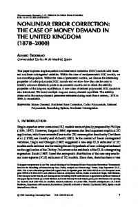
previous bit, which shows that a memory is being used. In the proposed scheme, we use a parallel BCH encoder which encodes the message as a whole block and uses no memory. The binary BCH codes are generalized Hamming codes and were first proposed by A. Hocquenghem in 1959. In 1960 Bose and Ray Chaudhuri did an independent research and came up with the same idea. Hence the BCH code is named after the three discoverers. BCH codes detect and correct randomly located bit errors in a stream of information bits according to its error correction capability (t). The burst error correcting codes, such as the Reed-Solomon codes, correct multiple errors within a symbol or multiple symbols, but all the bit errors must be within the same symbol. The most interesting aspect of the BCH codes over Reed-Solomon codes for our purpose is the simplicity in decoding the codewords. Here, we only need to figure out the bit’s location and not the correct value, as in the case of Reed-Solomon codes. The basic block diagram of the generic multiple bit error correction circuit using the binary BCH code is shown in Fig. 1. The overall design contains a parity prediction block, a syndrome generation block, an error-locator polynomial generation block, and a decoder, apart from the bit parallel multiplier circuit. B. BCH Encoder and Decoder Design
Sigt
....
Sig2
Sig1
Correction Block
.... coutm Fig. 2.
cout1
cout0
Syndrome generator and BCH decoder.
III. M ULTIPLE B IT E RROR C ORRECTION A. BCH Code The Bose-Choudhury-Hocquenghem (BCH) codes belong to the family of cyclic codes in which the message block is encoded using a polynomial g(x), called the generator polynomial. The generator polynomial is the least common multiplier (LCM) of the minimal polynomial for the selected powers with respect to GF(2m ), provided that each of the minimal polynomial should appear only once in the product. Here, the message is treated as a whole block and encoded one at a time rather than encoding continuously as in the case of convolution codes. The encoder block possesses no memory, hence no information of the previous message blocks. This style of encoding can be thought of as sliding an encoding window over the message bits. In the conventional BCH codes, the LFSR structure is used to encode incoming message bits one at a time. Hence, the present encoded bit depends on the
This section details the complete design of a BCH parallel encoder and decoder with an example. The bit parallel multiplier architecture is adopted from [12]. The general representation of BCH code is BCH(n, k, d), where n is the size of the codeword or, in other words, it is the sum of the message length (k), and the number of parity bits (p) used for encoding, and d is the minimum distance (dmin) between the codewords. The possible BCH codes for m ≥ 3 and t < 2m−1 is given by, Block length:
n = 2m−1
Number of check bits: n − k ≤ mt Minimum distance: dmin ≥ 2t + 1
(5) (6) (7)
The codeword is formed by adding the remainder after dividing the shifted message block by a special polynomial called the generator polynomial g(x). All the codewords will be a multiple of the generator polynomial. The generator polynomial is not just a minimal primitive polynomial, but a combination of several polynomials corresponding to the powers of the primitive element α in GF(2m ). In other words, g(x) is the least common multiple of the minimal polynomials over the various powers of the primitive element α (powers from α , α 2 , . . . , α 2t , where t is the error correction capability of the code). Then, � g(x) = lcm m1 (x), m2 (x), . . . , m2t (x) , (8) where m1 (x), m2 (x), . . . , m2t (x) are the minimal polynomials corresponding to the various powers of α . It is also noted that
TABLE I GF(24 ) ELEMENTS IN PB. GF(24 ) elements 0 1 α α2 α3 α4 α5 α6 α7 α8 α9 α 10 α 11 α 12 α 13 α 14
where, p0 = c0 + c2 + c4 , p0 = d0 + d2 + d4 + e0 + e1 + e2 + e3 , p1 = c0 + c1 + c2 + c3 + c4 , p1 = d0 + d1 + d2 + d3 + d4 , p2 = c0 + c1 + c3 , p2 = d0 + d1 + d3 + e1 + e2 + e3 , p3 = c1 + c2 + c4 , p3 = d1 + d2 + d4 + e0 + e2 + e3 , p4 = c0 + c3 + c4 , p4 = d0 + d3 + d4 + e0 + e2 , p5 = c0 + c1 + c2 , p5 = d0 + d1 + d2 + e2 , p6 = c1 + c2 + c3 , p6 = d1 + d2 + d3 + e0 + e3 , p7 = c2 + c3 + c4 , p7 = d2 + d3 + d4 + e1 , p8 = c0 + c2 + c3 , p8 = d0 + d2 + d3 + e0 + e1 + e3 , p9 = c1 + c3 + c4 , p9 = d0 + d3 + d4 + e0 + e2 . Hence, the final BCH encoded codeword for the bit parallel GF multiplier circuit is given as,
Bit vector 0000 0001 0010 0100 1000 0011 0110 1100 1011 0101 1010 0111 1110 0100 1111 1001
E(x) = c4 x14 + c3 x13 + c2 x12 + c1 x11 + c0 x10 + p9 x9 + p8 x8 + p7 x7 + p6 x6 + p5 x5 + p4 x4 +
every even power of a primitive element has the same minimal polynomial, hence Eq. (8) will be simplified to, � g(x) = lcm m1 (x), m3 (x), . . . , m2t−1 (x) . (9) The basic principle and design of the bit-parallel BCH code based multiple error correction scheme is explained with an example as follows. Let us consider a simple case of BCH(15, 5, 7), where n = 15 and k = 5. In this fairly small example, we consider bit-parallel PB multiplier over GF(25 ). Let c = [co , c1 , c2 , c3 , c4 ] be the outputs of the multiplier. Then, M(x) = c4 x4 + c3 x3 + c2 x2 + c1 x + c0 x
n−k
n−k
4
3
(10)
2
M(x) = x (c4 x + c3 x + c2 x + c1 x + c0 ) = c4 x14 + c3 x13 + c2 x12 + c1 x11 + c0 x10 , (11)
since n = 15 and k = 5 in this case. The parity check bits are generated by, P(x) = xn−k M(x) mod g(x).
(12)
Let α be the primitive element of GF(24 ), as shown in Table I. Here, P(x) = x4 + x + 1 is the primitive polynomial. The three minimal polynomials m1 (x), m3 (x), and m5 (x) are given by, m1 (x) = x4 + x + 1 m3 (x) = x4 + x3 + x2 + x + 1
(13) (14)
m5 (x) = x2 + x + 1.
(15)
For three bit error correction (t = 3), the generator polynomial for constructing the codeword is then given by, g(x) = lcm m1 (x), m3 (x), m5 (x)).
(16)
Substituting values of Eq. (13), Eq. (14) and Eq. (15) in Eq. (16) we get, g(x) = x10 + x8 + x5 + x4 + x2 + x + 1
(17)
Substituting Eq. (17) in Eq. (12) gives, P(x) =
p9 x9 + p8 x8 + p7 x7 + p6 x6 + p5 x5 + p4 x4 + p3 x3 +p2 x2 + p1 x1 + p0
(18)
p3 x3 + p2 x2 + p1 x + p0 .
(19)
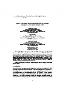
The parity bits (check bits) are generated by a parallel check bit generation unit as shown in Fig. 1. The resulting parity bits along with the multiplier outputs are passed to the syndrome generation blocks as shown in Fig. 2. For three bit error correction capability (t = 3), we need six (2 ×t) syndromes to be generated. The syndromes help us to determine whether the computed multiplication results are error free or not. In case of error free computation, the syndromes will be evaluated to zero. If the syndromes are nonzero, then that flags us the erroneous computation. The syndromes are calculated as follows, Si(x) = E(x)|x=1,α ,...,α 2t
(20)
The syndrome decoding is done by using the well known Peterson-Gorenstein-Zierler algorithm. Peterson noticed that we need only a few of the syndromes to effectively correct the bit errors. In our case for three bit error correction we need to calculate only syndromes S1, S3, and S5. The generalized equation for syndromes for the given example of BCH(15, 5, 7) are given as follows, S1 = s13α 3 + s12α 2 + s11α + s10, S3 = s33α 3 + s32α 2 + s31α +s30, S5 = s53α 3 +s52α 2 +s51α +s50, s10 = c4 +c3 + c2 + c0 + p8 + p7 + p4 + p0 , s11 = c2 + c1 + c0 + p9 + p7 + p5 + p4 + p1 , s12 = c3 + c2 + c1 + c0 + p8 + p6 + p5 + p2 , s13 = c4 + c3 + c2 + c1 + p9 + p7 + p6 + p3 , s30 = c4 + c0 + p9 + p5 + p4 + p0 , s31 = c4 +c3 + p9 + p8 + p4 + p3 , s32 = c4 +c2 + p9 + p7 + p4 + p2 , s33 = c4 + c3 + c2 + c1 + p9 + p8 + p7 + p6 + p4 + p3 + p2 + p1 , s50 = c4 + c2 + c1 + p9 + p8 + p6 + p5 + p3 + p2 + p0 , s51 = c4 + c3 + c1 + c0 + p8 + p7 + p5 + p4 + p2 + p1 , s52 = c4 + c3 + c1 + c0 + p8 + p7 + p5 + p4 + p2 + p1 , s53 = 0. Determining whether the computation is error free is not sufficient, and we also need to correct these errors in case if they are present. For this, we need to compute the error positions or error locations of the erroneous bits. To determine the error positions effectively, we need to decode the syndromes. The syndrome decoding block of the BCH based error correction technique contains an error locator polynomial generator block that finds the root of the error locator polynomial and a decoder that eventually corrects the erroneous bits based on the computed error position. For this purpose computed syndrome values are passed on to the error
Fig. 3. Block with area analysis of a 45-bit GF multiplier with 3-bit error correction.
of the error locator polynomial are based on exhaustive search methods. A widely known algorithm for finding the roots is the Chien search algorithm, in which all the possible values of the primitive element α , ranging from α 0 , α , . . . , α 2m−1 , are induced into the error locator polynomial to check if they satisfy the polynomial. In the proposed design, a bit parallel implementation of the Chien search algorithm is implemented. In particular, we proposed a scheme in which the root of the error locator polynomial is checked only among the powers of the primitive element α corresponding to the bit positions of the message bits, i.e. the multiplier output bits. The roots of the error locator polynomial corresponding to the parity bits are omitted in order to reduce the hardware complexity. For a 5-bit multiplier, we check whether α , α 2 , α 3 , α 4 , α 5 are roots of the error locator polynomial, which in turn corresponds to the bit positions c4 , c3 , c2 , c1 and c0 in the output of the multiplier. In other words, if α is a root of the error locator polynomial, it says that the bit c4 of the multiplier is erroneous, etc. The decoder corrects the erroneous bit(s) corresponding to the information provided by the parallel root search block. Based on this design principle, we have also extended the design to a 16-bit bit parallel PB multiplier over GF(216 ) and to a 45-bit bit parallel PB multiplier over GF(245 ).
locator polynomial computation block, as shown in Fig. 2. For the three (t = 3) bit error correction, we have three (t = 3) coefficients for the error locator polynomial. Let σ 1, σ 2, and σ 3 be the three coefficients of the error �locator polynomial. Then, σ 1 = S1, σ 2 = (S12 S3) + S5 /(S13 + S3), σ 3 = (S13 + S3 + S1S2). The above three equations give the coefficients σ 1, σ 2, and σ 3 of the error locator polynomial.
Overhead Analysis Original With Error Correction
180
160
140
120
100
80
60
40
20
0 With Error Correction Original Design
Fig. 5.
2 Error
3 Error
4 Error
5 Error
Overhead analysis of BCH based error correction scheme.
IV. E XPERIMENTAL R ESULTS Fig. 4. ModelsimTM simulation results of BCH code based multiple error correction.
Improved Error Locator Design: Once we have the error locator polynomial, the roots of the polynomial will give the error locations. The traditional algorithms for finding the roots
We have designed the BCH based error correction scheme in VHDL. For simulation and validation of the error correction technique, we have considered 16-bit and 45-bit bit parallel PB multipliers as design examples. Since the error correction logic is independent of the multiplier logic, this scheme can be extended for bit parallel multipliers of any size. The design was simulated using ModelsimTM and was synthesized using
TABLE II C OMPARISON WITH OTHER A PPROACHES . Property #errors correction Coding technique Overhead
[12] single Hamming >100%
[10] single LDPC 100%
the SynopsysTM (180nm technology) design compiler. Fig. 5 shows the area overhead for the various designs with 2, 3, 4, and 5 error correction for a 45-bit multiplier. Fig. 3 shows the area of the various blocks in our proposed multiple error correction scheme. Fig. 4 shows the snapshot of a typical ModelsimTM simulation result. During the simulations, we have introduced faults into the multiplier outputs randomly for checking the error correction capability of the proposed scheme. The highlighted parts in Fig. 4 show one among the many testing values. We have introduced errors in the intermediate stages of the multiplier, which in turn gave multiple bit errors at the multiplier output. In this case we have errors at bit positions 1, 2, and 16, however the cout values show the corrected final output from the BCH decoder. Although the example designs considered 2 to 5 bit error correction capability, based on the theory presented in this paper, we can easily extend its capability to more than five bits. The back end process, place and route, is done for a 45bit GF multiplier with three error correction capability using the Cadence EncounterTM tool set. The final layout of the design is shown in Fig. 6.
Fig. 6. Feature.
Layout of 45-bit GF Multiplier with Multiple Error Correction
Further, for a given error correction capability, the extra hardware comes down significantly for larger and more practical designs. For example, for the 5-, 16-, and 45-bit multipliers we observed that the extra hardware is 600%, 240%, and 150.4% respectively for 3-bit error correction capability. V. C ONCLUSIONS AND F UTURE WORK This paper proposed a technique for designing bit parallel multiple bit error correctable multipliers over GF(2m ) based
Proposed 3 Errors BCH 150.4%
Proposed 4 Errors BCH 164.04%
Proposed 5 Errors BCH 170.4%
on the BCH codes. We also presented an efficient bit parallel structure of the iterative Chien search algorithm for finding the roots of the error locator polynomial, comprising less area and time complexity. The experimental results showed that the proposed scheme has a lower complexity in terms of area and delay compared with the NMR based techniques. Also, compared to SEC techniques the hardware overhead is well within acceptable margins despite its enhanced capability. Future extensions of the proposed work will include fully testable versions of the proposed scheme for higher complexity bit parallel and digit serial architectures. Power and delay specs will be explored with advanced testable designs. R EFERENCES [1] A. Reyhani-Masoleh, and M. Anwar Hasan, “Fault Detection Architectures for Field Multiplication Using Polynomial Bases”, IEEE Trans. Computers, vol. 55, No. 9, Sept. 2006. [2] Mitra S., Seifert N., Zhang M., Shi Q and Kim K, “Robust System Design with Built-In Soft Error Resilience”, IEEE Computer, Vol. 38, Number 2, pp. 43-52, Feb. 2005. [3] C. R. Moratelli, E. Cota, M. S. Lubaszewski “A Cryptography Core Tolerant to DFA Fault Attacks”, Journal Integrated Circuits and Systems, pp-14-21, 2007. [4] Y. Jin, Y. Makris, “Hardware Torjans in Wireless Cryptographic ICs”, IEEE Design & Test Computers, January/February 2010. [5] J. Mathew, A. M. Jabir, H. Rahaman, D. K. Pradhan, “Single error Correctable Bit Parallel Multipliers over GF(2m )”, IET Comput. Digit. Tech., Vol. 3, Iss.3, pp. 281-288,2009. [6] A. Jabir, D. Pradhan, J. Mathew “GfXpress: A Technique for Synthesis and Optimization of GF(2m ) Polynomials”, IEEE Trans. CAD 27(4), 690–711, 2008. [7] G. B. Ratanpal, R. D. Williams,and T. N. Blalock, “An On-Chip Signal Suppression Countermeasure to Power Analysis Attacks”, IEEE Trans. on dependable and secure computing, vol. 1, no. 3, July 2004. [8] D. Boneh, R. A. DeMillo, and R. J. Lipton, “On the Importance of Eliminating Errors in Cryptographic Computations”, Journal of Cryptology, 14, pp. 101–119, 2001. [9] M. Ciet and M. Joye. Dueck, ”Elliptic Curve Cryptosystems in the Presence of Permanent and Transient Faults”, Designs, Codes and Cryptography, 36(1), July 2005, pp. 33–43. [10] J. Mathew, J. Singh, A. M. Jabir, M. Hosseinabady and D. K. Pradhan, “Fault Tolerant Bit Parallel Finite Field Multipliers using LDPC Codes”, IEEE, 2008. [11] G. Gaubatz and B. Sunar, ”Robust finite field arithmetic for faulttolerant public-key cryptography”, 2nd Workshop on Fault Tolerance and Diagnosis in Cryptography (FTDC), 2005. [12] A. Reyhani-Masoleh, and M. Anwar Hasan, “Low Complexity Bit Parallel Architectures for Polynomial Basis Multiplication over GF(2m )”, IEEE Trans. on Computers, Vol.53, No.8, pp.945-959, August 2004. [13] K. Wu, R. Karri, G. Kuznetsov and M. Goessel: “Low Cost Concurrent Error Detection for the Advanced Encryption Standard”, International Test Conference, pp.1242-1248, 2004. [14] D. K. Pradhan, “A Theory of Galois Switching Functions”, IEEE Trans. Computers, vol. 27, no. 3, pp.239-248, Mar. 1978. [15] O. Keren “One-to-Many: Context-Oriented Code for Concurrent Error Detection” Journal of Electron Test, vol. 26, pp. 337-353, 2010 [16] E. D. Matrovito, “VLSI Achitectures for Computation in Galois Fields.” Ph.D. thesis, Linkoping University, Linkoping Sweden, 1999.