reverse engineer a software system. Due to space limitations ... input field, e.g., metric values and other semantic information whether the class is abstract, etc.
CodeCrawler – An Extensible and Language Independent 2D and 3D Software Visualization Tool Michele Lanza Software Engineering Group – Department of Informatics University of Zurich, Switzerland Stéphane Ducasse Software Composition Group – Institute of Computer Science University of Bern, Switzerland Abstract CodeCrawler is an extensible and language independent software visualization tool. It has been validated in several industrial case studies over the past years. CodeCrawler enables the fast exploration of new visualization ideas. It implements and visualizes polymetric views, visualizations of software enriched with information such as software metrics and other source code semantics. It provides a rich set of views that can be customized using a large set of metrics. While CodeCrawler is mainly targeted at visualizing object-oriented software, in its latest implementation it has become a general information visualization tool.
1. Introduction CodeCrawler is a software and information visualization tool (Stasko et al. 1998, Ware 2000) which implements polymetric views, lightweight 2D- and 3D- visualizations enriched with semantic information such as metrics or information extracted from various code analyzers. It relies on the FAMIX metamodel (Demeyer et al., 2001) which models object-oriented languages such as C++, Java, Smalltalk, but also procedural languages like COBOL. FAMIX has been implemented in the Moose reengineering environment that offers a wide range of functionalities like metrics, query engines, navigation, etc. (Ducasse et al., 2004). We shortly introduce the principles of polymetric views and then give some examples of the visualizations that CodeCrawler enables the user to achieve. The proposed visualizations support both program comprehension and problem detection, and target three different aspects of software systems, 1
namely coarse-grained, fine-grained, and evolutionary aspects. We apply CodeCrawler on itself and hightlight some of the implementation characteristics.
2. The Principles of a Polymetric View The visualizations implemented in CodeCrawler are based on the polymetric views described by Lanza (Lanza 2004, Lanza and Ducasse 2003). The principle is to represent source code entities as nodes and their relationships as edges between the nodes, but to use figure shapes to convey semantics about the source code entities they represent.
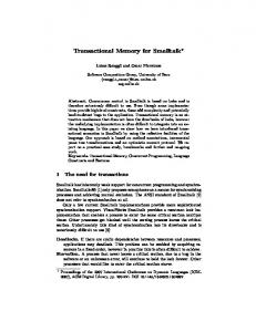
Figure 1 - The Principles of a Polymetric View.
In Fig. 1 we see that, given two-dimensional nodes representing entities and edges representing relationships, we enrich these simple visualizations with up to 5 metrics on the node characteristics and 2 metrics on the edge characteristics: • Node Size. The width and height of a node can render two measurements. We follow the convention that the wider and the higher the node, the bigger the measurements its size is reflecting. • Node Color. The color interval between white and black can display a measurement. Here the convention is that the higher the 2
•
• •
measurement the darker the node is. Thus light gray represents a smaller metric measurement than dark gray (Tufte 2001). Node Position. The X and Y coordinates of the position of a node can reflect two other measurements. This requires the presence of an absolute origin within a fixed coordinate system therefore, not all views can exploit such metrics (e.g., in a tree view, the position is given by the tree layout and cannot be set by the user). Edge Width. The width of an edge can render a measurement: the wider the edge, the higher the measurement. Edge Color. The color interval between white and black can display a measurement. Here the convention is that the higher the measurement the darker the edge is.
Figure 2 - A screenshot of CodeCrawler visualizing itself with a System Complexity view. This view uses the following metrics: Width metric = number of attributes, Height metric = number of methods, Color Metric = number of lines of code.
Example. In Fig. 2 we see CodeCrawler visualizing itself with a polymetric view called System Complexity. The metrics used in this view are the number of attributes for the width, the number of methods for the height, and the number of lines of code for the color of the displayed class nodes.
3
The polymetric views in CodeCrawler can be created either programmatically in Smalltalk by constructing the view objects, or over an easy-to-use View Editor, where each view can be composed using drag & drop.
Figure 3 - CodeCrawler's View Editor.
In Fig. 3 we see CodeCrawler’s View Editor with the specification of the System Complexity view: the user can freely compose and specify the types of items that will be displayed in a view and also define the way the visualization will be performed: for every node and edge the user can choose from a selection of metrics.
3. Polymetric View Examples CodeCrawler visualizes three different types of polymetric views: coarsegrained, fine-grained, and evolutionary views.
3.1 Coarse-grained Polymetric Views Such views are targeted at visualizing very large systems (from several tens of thousands to several millions of lines of code). 4
Figure 4 - A System Hotspots view of 1.2 million lines of C++ code. The nodes represent classes. This view uses the following metrics: Width = height = number of methods, color = hierarchy nesting level.
Example. In Fig. 4 we see a System Hotspots view of a 1.2 million lines of C++ industrial application. The view uses the number of methods for the width and height of the class nodes. We gather for example from this view that there are classes with several hundreds of methods (at the bottom), while at the top we see a large number of C++ structs, identifiable by the fact that most of them do not implement any methods. We spot large classes deeply located deep in hierarchy as large dark nodes.
3.2 Fine-grained Polymetric Views The most prominent fine-grained view is the Class Blueprint view, a visualization of the internal structure of classes and class hierarchies (Lanza and Ducasse, 2001). A class blueprint is a visualization of a semantically augmented call graph and its specific semantics-based layout. The objective of this view is to help a programmer to develop a mental model of the classes he browses and to offer support for reconstructing the logical flow of method calls and attribute accesses. It is augmented in various aspects: • A class blueprint is structured according to layers that group the methods and attributes. • The nodes representing a class’ methods and attributes are colored according to semantic information, e.g., whether a method is abstract, overriding other methods, returning constant values, etc. 5
•
The nodes vary in size depending on source code metrics information. A Class Blueprint divides each class into 5 layers, as we can see in Fig. 5.
Figure 5 - The layered structure of a class blueprint view.
We distinguish the following layers: 1. Initialization Layer. The methods contained in this first layer are responsible for creating an object and initializing the values of the attributes of the object. 2. External Interface Layer. The methods contained in this layer represent the interface of a class to the outside world, i.e., it contains all methods of a class which are not called by other methods of the same class. 3. Internal Implementation Layer. The methods contained in this layer represent the core of a class and are not supposed to be visible to the outside world, i.e., this layer contains all methods which are at least called by another method of the same class. 4. Accessor Layer. This layer is composed of accessor (getters and setters) methods. 5. Attribute Layer. The attribute layer contains all attributes of the class. The attributes are connected to the methods in the other layers by means of access relationships. 6
Moreover we use nominal colors denote semantic information such as whether a method is abstract, and accessor a getter or a setter, whether a method is returning a constant value, whether it is overriding or extending methods in the superclasses, etc.
Figure 6 - A Class Blueprint view of a small hierarchy of 4 classes written in Smalltalk.
Example. In Fig. 6 we see a class blueprint view of a small hierarchy of 4 classes. We use the class blueprint view to develop a pattern language for reverse engineering (Lanza and Ducasse, 2001). In the present example we see the following patterns: • Pure overrider: The three subclasses implement only overriding methods (denoted by the brown color). • Siamese Twin: The two subclasses on the left and the right are structurally identical, not only do they implement exactly the same methods (the methods differ within their body), their static invocation structure is also the same. • Template Method: The method node in the superclass annotated as A is a concrete method which only invokes abstract methods (denoted by their cyan color). This is known as the template method design pattern (Gamma et al., 1995). 7
•
• •
Inconsistent Accessor Use: The superclass defines only two accessors (positioned in the second layer from the right), while it defines three attributes (last layer to the right). These two accessors do not have ingoing edges: at least in the context of this hierarchy they are not used at all. Direct Attribute Access: We see that the attribute nodes of the superclass are directly accessed by several methods. T he methods annotated as B and C seem to play an important role in these classes: They are invoked by many methods (several ingoing edges) and they invoke several methods (numerous outgoing edges).
3.3 Evolutionary Polymetric Views The most prominent view is the Evolution Matrix view, a visualization of the evolution of complete software systems (Lanza and Ducasse, 2002). The idea is to represent all the system versions as columns and all the classes (all versions) as rows of the Evolution Matrix and to add semantic information on the visualization. In Fig. 7 we see an example of such a visualization, which again allows us to develop a pattern language applicable in the context of software evolution. The view is enriched with the metrics ‘number of methods’ for the width and ‘number of attributes’ for the height of the class nodes. Other combinations of metrics are also possible and yield different evolutionary views. We can recognize the following patterns: • The set of classes which survived the complete evolution of the system since the beginning is annotated as persistent classes.
8
Figure 7 - An Evolution Matrix view of 38 versions of an application written in Smalltalk.
•
• •
The dayfly classes denote classes which have existed during one version of the system and have then be removed. Probably the developer tried out something and removed this 'experiment' right away. The pulsar class denotes a class whose size in terms of number of methods and attributes varies, making it thus an expensive class of this system. A long stable phase where the system did not grow in terms of number of classes, and two major leaps where the system rapidly grew between two versions.
4. CodeCrawler at Work In this section we shortly illustrate how CodeCrawler can be used to reverse engineer a software system. Due to space limitations we only show excerpts of the whole process. However, polymetric views as implemented in CodeCrawler are intrinsically interactive and only of limited use when used in a static way, i.e., only looking at them is not enough.
9
Figure 8 - CodeCrawler at Work. Every item has its own menu.
Example. An example of interactivity (See Fig. 8) is that when the user passes with the mouse pointer over a node or an edge, the item is highlighted and information about the subject item is displayed in CodeCrawler’s top input field, e.g., metric values and other semantic information whether the class is abstract, etc. Moreover, using a context menu the viewer can interact with the item in focus. The Case Study. As case study we have chosen CodeCrawler itself (Version 4.510) to also explain its architecture and design on-the-fly. CodeCrawler is a small system consisting of slightly less than 9000 lines of Smalltalk code (including its 80 unit tests) in 122 classes. CodeCrawler uses Moose as metamodel and repository for entities and the HotDraw framework for visualizing. Approaching the System. First of all we need to model the source code of a software system. This task is completely delegated to the Moose reengineering environment (see corresponding chapter in this book), since CodeCrawler is tied to it at an implementation level (both systems are written in Smalltalk). CodeCrawler can thus visualize systems written in different languages such as C++, Java, COBOL, etc. Once the system is parsed, CodeCrawler can directly generate the needed nodes and edges representing the software entities and relationships. 10
In Fig. 2 we see CodeCrawler displaying itself with a System Complexity view. We gather that it consists mainly of 2 inheritance hiearchies. CodeCrawler greatly relies on interactivity, and a first approach to understanding such a system consists in a combination of selecting and grouping, with optional use of coloring. The goal is basically to “tear the system apart”. We have done so and show the results in Fig. 9.
Figure 9 - CodeCrawler after being torn apart in subsystems using grouping facilities.
Fig. 9 shows that CodeCrawler consists of: • A main application framework (the largest hierarchy with a root class named CCRoot) which seems to contain two subhierarchies. • A graphical user interface hiearchy consisting of classes providing dialogs and windows. • Some classes which are subclasses of the HotDraw framework classes (= an extension of the visualization framework, since HotDraw does not provide all functionalities needed by CodeCrawler). • Some classes which are subclasses of the Moose environment (= an extension of the metamodel). • The main CodeCrawler class itself with a small subclass for the purpose of visualizing software evolution. In Fig. 10 we take a closer look at the largest hierarchy with yet another System Complexity view. We have first removed the root class (CCRoot) which is basically empty (denoted by its tiny size as we see in Fig. 2) and have annotated the resulting subhierarchies. We see in Fig. 10 the following information: 11
• •
A major hierarchy is dedicated to the layouts implemented in CodeCrawler. A small hierarchy consisting of three classes: CCItem, CCNode, and CCEdge. They represent the actual core of CodeCrawler’s design, since it is mainly based on the notion of graphs containing items: nodes and arcs (edges).
Figure 10 - CodeCrawler's main application framework.
•
A small hierarchy consisting of 4 classes named CCItemFigureModel (the top class node), CCNodeFigureModel, CCEdgeFigureModel, and CCCompositeFigureModel (the smallest node). We have named this hierarchy a visualization engine bridge and provide a more detailed explanation below using a Class Blueprint view. • A major hierarchy which we have named Plugin hierarchy. It actually mimics the hierarchies of entities of entities and relationships defined in the FAMIX metamodel, and there are classes named CCFAMIXClassNodePlugin, CCFAMIXInheritanceEdgePlugin, etc. A good portion of CodeCrawler’s functionality is contained in this hierarchy: everything which is accessible from the context menus of the respective nodes and edges. We want to take a closer look at the visualization bridge hierarchy using a Class Blueprint view. We display the root class named CCItemFigureModel to see if we can infer information about the complete hierarchy. From Fig. 11 we gather that this class has been built according to the Facade design pattern (Gamma et al., 1995): in the public interface layer there is a very heavy use of delegation (this is denoted by the yellow method nodes). Moreover the class implements some abstract methods (cyan nodes) and has practically no internal implementation. Actually this class acts as a 12
bridge between the item hierarchy and the hierarchy of the figures. We also see that the accessors do not have a perfect read/write (red/orange) pattern, thus indicating that at least some accessors were not generated, but created by hand.
Figure 11 - On the left side a regular Class Blueprint view of the class CCItemFigureModel, on the right side the same blueprint, but displaying names instead of metrics. This class is built according to the Facade design pattern.
The Class Blueprint view delivers its full potential only if the viewer looks carefully at what he sees and pays attention to irregularities and particularities in the visualizations. In the remainder of the chapter we show some more polymetric views that CodeCrawler delivers about itself. Method Efficiency Correlation View. This view makes use of position metrics and visualizes methods. It uses a simple scatterplot layout enhanced with metrics: the horizontal position represents the number of lines of code, while the vertical position represent the number of statements of each method.
13
Figure 12 - Method Efficiency Correlation View of CodeCrawler's 1351 methods.
In Fig. 12 we have displayed all 1351 methods of CodeCrawler. We see that most methods align themselves along a 45 degree correlation axis, meaning that most methods contain on the average 1 statement per line. We have annotated to methods which spring to the eye: one has 56 lines but no statement: upon closer inspection it reveals that its method body is completely commented. This view can also be used for system quality assessment: to the right of the vertical line there are all methods longer than 7 lines, which is the average length of a Smalltalk method. By interacting with the items in the view one can easily filter out overlong methods that perhaps could be split. Direct Attribute Access View. This view visualizes attributes with a simple layout and uses as size metric for both width and height the number of direct accesses on each attribute. Moreover, we colorized the attributes for whom accessor methods have been defined with a gray color.
14
Figure 13 - A Direct Attribute Access view on the attributes defined in CodeCrawler's classes.
In Fig. 13 we see all attributes defined in the classes of CodeCrawler. We see that some attributes are heavily accessed (the largest attribute node is directly accessed 61 times (not using accessor methods)), but we also see that for this attribute there are no accessor methods. The other annotated attribute node reveals a possible problem: this attribute is directly accessed 32 times, but evidently there are accessor methods defined for it which do not get used consistently. 3D Polymetric Views. Recently CodeCrawler has been extended to enable 3D visualizations. In Fig. 14 we see that the tool has not changed its functionality in 3D, but offers the same context functionality as in the 2D version. The user can also freely switch between 2D and 3D views. The authors still have to assess which are the benefits of having an additional dimension at disposition and how to best exploit it in terms of functionality, navigability, and usability.
15
Figure 14 - CodeCrawler 3D visualizing the System Complexity view in 3D. The functionality offered by the context menus is the same as in the 2D version.
6. Extending CodeCrawler During the case studies we have performed we have learned that the extensibility and the flexibility of a tool is key to successful reverse engineering: every case study comes with its own particularities, and being able to adapt to contexts such as the implementation language, naming conventions, structural particularities, etc. is crucial. CodeCrawler can be extended in the following ways: • defining new views: new views can be composed using the view editor or by programmatically composing them using Smalltalk code. • defining new entities to visualize: if we want to visualize a new kind of entity, such as package, we need to write a small plugin class which inherits a lot of behavior and we have to override 4 small methods which are mainly used for display purposes. If we then want 16
•
•
to add more intelligence to a plugin we can do so by implementing menu items defining new metrics: if we want to add a new metric, we can write a new PropertyOperator which takes care of computing the value and assigns it to the entity or its plugin. The framework for computing metrics is implemented in the Moose reengineering environment. Visualizing systems in different languages. CodeCrawler is based on Moose regarding fact extraction and acquisition from software systems (see chapter on the Moose environment in this book). The problem of visualizing other languages can thus be delegated to extending the Moose reengineering environment: Since CodeCrawler has a well-defined interface to the FAMIX metamodel implemented in Moose, there are usually no changes to be made in CodeCrawler. However, if a language supports new types of constructs that need to be visualized, we need to define new plugin classes.
7. Industrial Validation CodeCrawler has been used to reverse engineer industrial systems several times and is also used in conjunction with Moose by consultants to assess software systems. Due to non-disclosure agreements with the industrial partners we cannot provide detailed descriptions of our experiences, but limit ourselves to provide a list of case studies (industrial and non-industrial) that we have performed. System
Language
Lines of Code
Z (Network Switch) Y (Network Switch) X (Multimedia) W (Payroll) SORTIE (Forest Management) Duploc (Research Prototype) Jun (Multimedia and 3D Framework) JBoss (Application Server) V (Logistics)
C++ C++/Java Smalltalk COBOL C/C++ Smalltalk Smalltalk Java C++
1’200’000 140’000 600’000 40’000 28’000 32’000 135’000 300’000 120’000
Classes ~2300 ~400 ~2500 ~70 ~230 ~700 ~4900 ~300
Tab. 1 – A Selection of the Case Studies performed with CodeCrawler.
In Tab. 1 we see that the systems were written in different programming languages and have sizes quite different from each other. The point in 17
common of all case studies were the narrow time constraints imposed on us: we never had more than one week to reverse engineer the systems.
Figure 15 - A System Complexity view of a large C++ hierarchy consisting of more than 200 classes.
E x a m p l e . In Fig. 15 we see what we have termed a flying saucer hierarchy: it is composed of more than 200 classes with a root class that has ca. 100 direct subclasses. A recommendation to the developers was to try to introduce a ‘middle layer’ of classes and to push up functionality from all sibling classes.
8. Conclusion We presented CodeCrawler, a visualization tool that enriches software visualizations with metrics and other semantic information. We call these enriched visualizations polymetric views. The polymetric views are customizable and can be easily adapted to different contexts. We used the polymetric views in three different reverse engineering contexts, namely (1) coarse-grained software visualization, (2) fine-grained software visualization, and (3) evolutionary software visualization. We claim that polymetric views can help to greatly reduce the complexity of a reverse engineering process. Moreover, the added metrics and semantic information increase the amount of information that is visually transmitted to the viewer. The polymetric views support opportunistic code reading, i.e., the goal of the polymetric views is not to replace code reading, but to point the viewer to locations of interest. To validate our claim we applied different polymetric views on several case studies, one of which are presented here, with the goal of understanding the subject systems. Closing Words. All too often research conducted in the field of software visualization, a descendant of information visualization, is ignoring the great insights obtained by people like Bertin and more recently Tufte, Ware, and Stasko and others. This generated in the last few years dozens of software visualization tools that mainly offer the same functionalities and introduce little new insights. We believe that in order for software visualization to become a respected, serious, and established research field, software visualization researchers should settle on a common benchmark which would 18
allow one to accept and/or reject new/old ideas and to discuss these ideas more critically. Moreover, to have an impact on software industry, the tools must be integrated with existing IDEs, since developers are reluctant to change their working habits.
9. Tool Information CodeCrawler's implementation started in 1998 as part of Michele Lanza's Master and Ph.D. work, as part of the European FAMOOS ESPRIT Project. It has been used for various industrial consultancy projects since its first implementation and has been re-implemented 4 times since then. In its newest implementation it has become a general information visualization tool (e.g., visualization of concept lattices (Arévalo et al., 2003) and websites) and also supports 3D-Visualizations (Wysseier, 2004). CodeCrawler uses currently the HotDraw framework for the 2D visual output and the Jun framework for the 3D visual output. It uses the Moose reengineering environment for the data input. In Fig. 16 we see a schematic description of CodeCrawler’s general architecture. Figure 16 - The general architecture of CodeCrawler, composed of 3 main
subsystems: the core, the metamodel, and the visualization engine.
9.1 Tool Availability CodeCrawler is implemented in Smalltalk under the BSD license: it is free and open source software. It runs on every major platform (Windows, Mac OS, Linux, Unix) and is freely available for download. Currently the webpage is located at: http://www.iam.unibe.ch/~scg/Research/CodeCrawler/. 19
Moreover, CodeCrawler is also available as free goodie on the VisualWorks Smalltalk CD, a professional, commercial development environment developed and sold by the company Cincom which however also exists in a non-commercial version freely available for download at: http://www.cincomsmalltalk.com/
Bibliography G. Arévalo, S. Ducasse, and O. Nierstrasz (2003). “X-Ray views: Understanding the internals of classes”, in Proceedings of ASE 2003 (18th IEEE International Conference on Automated Software Engineering), Montreal, Canada, IEEE Computer Society Press, Los Alamitos (CA), pp. 267 - 270. S. Demeyer, S. Tichelaar, and S. Ducasse (2001), “FAMIX 2.1 — the FAMOOS information exchange model”, Technical report, University of Bern. S. Ducasse, T. Girba, M. Lanza, and S. Demeyer (2004). “Moose: a Collaborative Reengineering Environment” in Tools for Software Maintenance and Reengineering, Liguori, Napoli, Italy. E. Gamma, R. Helm, R. Johnson, and J. Vlissides (1995), Design Patterns: Elements of Reusable Object-Oriented Software, Addison Wesley, Reading, Mass. (USA). M. Lanza and S. Ducasse (2001), “A Categorization of Classes based on the Visualization of their Internal Structure: the Class Blueprint”, in Proceedings of OOPSLA 2001 (16th ACM Conference on Object-Oriented Programming, Systems, Languages, and Applications), Tampa Bay, Florida (USA), ACM Press, pp. 300 – 311. M. Lanza and S. Ducasse (2002), “Understanding Software Evolution using a Combination of Software Visualization and Software Metrics”, in Proceedings of LMO 2002 (8th International Conference on Langages et Modeles á Objects), Montpellier, France, Hermes Science Publications, Paris, France, pp. 135 – 149. M. Lanza (2004), “Object-Oriented Reverse Engineering – Coarse-grained, Finegrained, and Evolutionary Software Visualization”, Ph.D. Thesis, University of Bern. M. Lanza and S. Ducasse (2003), “Polymetric Views — A Lightweight Visual Approach to Reverse Engineering”. IEEE Transactions on Software Engineering, 29(9): 782–795, Sept. 2003. J. Stasko, J. Dominque, M. H. Brown, and B. A. Price (1998), “Software Visualization – Programming as a Multimedia Experience”, The MIT Press. E. Tufte (2001), “The Visual Display of Quantitative Information”, Graphics Press. C. Ware (2000), “Information Visualization”, Morgan Kaufman Publishers. C. Wysseier (2004), “CCJun – Polymetric Views in Three-dimensional Space”, Technical Report, University of Bern, 2004.
20