Jianle Chen, Ying Chen, Marta Karczewicz, Xiang. Li, Hongbin Liu, Li Zhang, Xin Zhao. Qualcomm Incorporate. 5775 More House Drive, San Diego, 92130, CA, ...
Coding tools investigation for next generation video coding based on HEVC Jianle Chen, Ying Chen, Marta Karczewicz, Xiang. Li, Hongbin Liu, Li Zhang, Xin Zhao Qualcomm Incorporate 5775 More House Drive, San Diego, 92130, CA, United States ABSTRACT The new state-of-the-art video coding standard, H.265/HEVC, has been finalized in 2013 and it achieves roughly 50% bit rate saving compared to its predecessor, H.264/MPEG-4 AVC. This paper provides the evidence that there is still potential for further coding efficiency improvements. A brief overview of HEVC is firstly given in the paper. Then, our improvements on each main module of HEVC are presented. For instance, the recursive quadtree block structure is extended to support larger coding unit and transform unit. The motion information prediction scheme is improved by advanced temporal motion vector prediction, which inherits the motion information of each small block within a large block from a temporal reference picture. Cross component prediction with linear prediction model improves intra prediction and overlapped block motion compensation improves the efficiency of inter prediction. Furthermore, coding of both intra and inter prediction residual is improved by adaptive multiple transform technique. Finally, in addition to deblocking filter and SAO, adaptive loop filter is applied to further enhance the reconstructed picture quality. This paper describes above-mentioned techniques in detail and evaluates their coding performance benefits based on the common test condition during HEVC development. The simulation results show that significant performance improvement over HEVC standard can be achieved, especially for the high resolution video materials. Keywords: HEVC, video coding standard, VCEG, MPEG
1. INTRODUCTION HEVC, the High Efficiency Video Coding standard, is the state-of-art video coding standard developed by the Joint Collaborative Team on Video Coding (JCT-VC) of the ITU-T VCEG and ISO/IEC MPEG standardization organizations. The first edition of the HEVC standard has been finalized in January 2013[1][2]. In ISO/IEC, the HEVC standard is MPEGH Part 2 (ISO/IEC 23008-2) and in ITU-T it became ITU-T Recommendation H.265. HEVC provide approximately a 50% bit rate savings for equivalent perceptual quality relative to the prior generation of video standard, H.264/MPEG-4 AVC (especially higher gain is achieved for high-resolution video). Although HEVC improve the coding efficiency significantly, there is still industry needs to further reduce the video bandwidth without scarifying the user experience [3]. Recently, both MPEG and VCEG have started the preparation work for the investigation of next generation video coding standard [4][5]. Therefore, it is desirable to study the technical possibilities for a next generation video codec. In this paper, a list of coding tools that can improve the coding efficiency of HEVC are investigated.
2. HEVC OVERVIEW As most previous video coding standard, HEVC employs the hybrid video coding framework. The basic structure of HEVC is same to its predecessor and it has the following highlighted features that improve the coding efficiency [2]. Quadtree-based block representation: In the previous standards, the macroblock wit fixed size (16x16 samples) is used. The analogous structure in HEVC is the coding tree unit (CTU), the size of CTU can be up to 64x16 samples. The larger block size results in better compression efficiency, especially for the high resolution video. To get flexible block representation, CTU can be split into CUs with quadtree structure. The root of the CU quadtree is the CTU. The minimum CU size is 8x8 in HEVC. The decision whether to code block using inter-picture prediction or intra-picture prediction is made at the CU level. Depending on the basic prediction type, CU can then be further split into 2 or 4 Prediction Units (PU). The prediction residual is coded using block transforms with quadtree structure. A transform unit (TU) tree structure has its root at the CU level. The TU sizes are 4×4, 8×8, 16×16, and 32×32.
Applications of Digital Image Processing XXXVIII, edited by Andrew G. Tescher, Proc. of SPIE Vol. 9599, 95991B · © 2015 SPIE · CCC code: 0277-786X/15/$18 doi: 10.1117/12.2193681
{cjianle, cheny, martak, lxiang, hongbinl, lizhang, xinzhao}@qti.qualcomm.com; phone: +1-858-651-8028 Proc. of SPIE Vol. 9599 95991B-1 Downloaded From: http://proceedings.spiedigitallibrary.org/ on 03/18/2016 Terms of Use: http://spiedigitallibrary.org/ss/TermsOfUse.aspx
Motion vector signaling: Advanced motion vector prediction (AMVP) is used, including derivation of several most probable candidates based on data from spatial adjacent PUs and temporal adjacent PUs in the reference picture. A “merge” mode for MV coding can be also used, allowing the inheritance of MVs from neighboring PUs. Motion compensation: Quarter-sample precision is used for the MVs, and 7-tap or 8-tap filters are used for interpolation of fractional-sample positions (compared to 6-tap filtering of half-sample positions followed by bi-linear interpolation of quarter-sample positions in H.264/MPEG-4 AVC). Similar to H.264/MPEG-4 AVC, multiple reference pictures are used. Intra-picture prediction: The decoded boundary samples of adjacent blocks are used as reference data for spatial prediction in PU regions when inter-picture prediction is not performed. Intra prediction supports 33 directional modes (compared to 8 such modes in H.264/MPEG-4 AVC), plus planar (surface fitting) and DC (flat) prediction modes. Sample adaptive offset (SAO): SAO is a non-linear amplitude mapping filter after the deblocking filter. The goal is to better reconstruct the original signal amplitudes by using a look-up table that is described by a few additional parameters that can be determined by histogram analysis at the encoder side.
3. DESCRIPTION OF PROPOSED METHODS In this paper, the basic structure of HEVC keeps unchanged and several modules of HEVC is further improved. Large block sizes and the quadtree structure of HEVC provide significant coding benefit. Therefore, in this paper, we extend the HEVC to support larger CTU and larger transforms. In addition, several well-known tools, such as Adaptive Loop Filter (ALF)[6], Linear Model (LM) prediction mode[10], Overlapped Block Motion Compensation (OBMC)[13] and Adaptive Transform are further studied and enhanced[14]. Furthermore, Advanced Temporal Motion Vector Prediction (ATMVP) that extends the current Temporal Motion Vector Prediction (TMVP) design in HEVC and applies the TMVP-like motion prediction on a sub-Prediction Unit (sub-PU) level, is proposed. Larger Coding Tree Block and Larger Transform Unit Large block size in HEVC provides significant coding performance improvement. In HEVC, CTU size is constrained to no larger than 64x64. However for videos with very high resolutions, such as 4K and 8K UHD sequences, 64x64 CTU is not efficient enough. Therefore, we further extend CU structure to support larger CTU size. By default 256x256 CTU size is used. The CU quadtree structure and the PU partition scheme is kept unchanged. In HEVC, up to 32x32 transform is supported. However, for larger resolution contents like 4K videos, larger transforms may provide better transform efficiency. Therefore, in this paper, a 64x64 DCT is proposed to collaborate with the existing transforms in HEVC to further improve the coding efficiency. The proposed 64x64 DCT matrix is a straightforward extension to the transform matrices used in HEVC. However, to reduce the computational complexity, only the top-left (lower-frequency) 32x32 coefficients among the 64x64 transformed block are maintained and the remaining higherfrequency coefficients are not calculated and simply zeroed out. The integer transform matrix Ti,j, where 𝑖𝑖, 𝑗𝑗 ∈ [0, 63] is derived by scaling the DCT-II matrix by S, followed by rounding. 2
𝑇𝑇𝑖𝑖,𝑗𝑗 = �𝑆𝑆 ∙ 𝑤𝑤0 ∙ � ∙ cos � 𝑁𝑁
𝜋𝜋∙𝑖𝑖∙(2𝑗𝑗+1) 128
� + 0.5�, where 𝑤𝑤0 = � √0.5, 𝑖𝑖 = 0 1, otherwise
(1)
where the scaling factor S is set equal to 256√64 to keep better orthogonality of the transform matrix. Furthermore, to keep the intermediate values of the transformed coefficients within the range of 16-bit, after horizontal and after vertical transform, all the coefficients are right shifted by 2 more bits, compared to the right shift used in the current HEVC transforms. Adaptive Loop Filter ALF is a quite efficient coding tool proposed during the development of HEVC. However, it was not finally adopted in HEVC due to complexity issue. In this paper, we investigate ALF in HM-3 [6][7] with simplification and improvement. In HM-3, ALF has two modes: block based adaptation and region based adaptation. To achieve a better tradeoff between encoding complexity and coding efficiency while keeping the worst-case decoding complexity unchanged, we proposed to only keep one mode: block based adaptation. The mode is described as follows. First, each 4x4 luma block in a picture is classified to one group from totally 15 groups based on 1D Laplacian direction (up to 3 directions) and 2D Laplacian activity (up to 5 activity values). The calculation of direction 𝐷𝐷𝐷𝐷𝑟𝑟𝑏𝑏 and unquanitzed
Proc. of SPIE Vol. 9599 95991B-2 Downloaded From: http://proceedings.spiedigitallibrary.org/ on 03/18/2016 Terms of Use: http://spiedigitallibrary.org/ss/TermsOfUse.aspx
activity 𝐴𝐴𝐴𝐴𝑡𝑡𝑏𝑏 is shown in equation (2) through (5), where 𝐼𝐼̂𝑖𝑖,𝑗𝑗 indicates a reconstructed pixel with relative coordinate (𝑖𝑖, 𝑗𝑗) to the top-left of the 4x4 block. 𝐴𝐴𝐴𝐴𝑡𝑡𝑏𝑏 is further quantized to the range of 0 to 4 inclusively as described in [7]. 𝑉𝑉𝑖𝑖,𝑗𝑗 = �𝐼𝐼̂𝑖𝑖,𝑗𝑗 × 2 − 𝐼𝐼̂𝑖𝑖,𝑗𝑗−1 − 𝐼𝐼̂𝑖𝑖,𝑗𝑗+1 �
(2)
𝐻𝐻𝑖𝑖,𝑗𝑗 = |𝐼𝐼̂𝑖𝑖,𝑗𝑗 × 2 − 𝐼𝐼̂𝑖𝑖−1,𝑗𝑗 − 𝐼𝐼̂𝑖𝑖+1,𝑗𝑗 |
(3)
1, 𝑖𝑖𝑖𝑖 (∑3𝑖𝑖=0 ∑3𝑗𝑗=0 𝐻𝐻𝑖𝑖,𝑗𝑗 > 2 × ∑3𝑖𝑖=0 ∑3𝑗𝑗=0 𝑉𝑉𝑖𝑖,𝑗𝑗 ) 𝐷𝐷𝐷𝐷𝑟𝑟𝑏𝑏 = �2, 𝑖𝑖𝑖𝑖 (∑3𝑖𝑖=0 ∑3𝑗𝑗=0 𝑉𝑉𝑖𝑖,𝑗𝑗 > 2 × ∑3𝑖𝑖=0 ∑3𝑗𝑗=0 𝐻𝐻𝑖𝑖,𝑗𝑗 ) 0, 𝑜𝑜𝑜𝑜ℎ𝑒𝑒𝑒𝑒𝑒𝑒𝑒𝑒𝑒𝑒𝑒𝑒
(4)
𝑗𝑗+1
𝑖𝑖+1 ∑𝑛𝑛=𝑗𝑗−1(𝑉𝑉𝑚𝑚,𝑛𝑛 + 𝐻𝐻𝑚𝑚,𝑛𝑛 )) 𝐴𝐴𝐴𝐴𝑡𝑡𝑏𝑏 = ∑3𝑖𝑖=0 ∑3𝑗𝑗=0(∑𝑚𝑚=𝑖𝑖−1
(5)
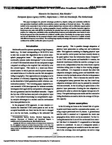
Then a group index is assigned to each 4x4 block according the value of 𝐷𝐷𝐷𝐷𝑟𝑟𝑏𝑏 and 𝐴𝐴𝐴𝐴𝑡𝑡𝑏𝑏 of the block. Therefore, up to 15 (5x3) sets of ALF parameter could be signalled for luma component of a picture. To save the signaling cost, groups with neighboring index values may be further merged. For each group (or merged group), a set of ALF coefficients are signaled. Up to three circular symmetric filter shapes (as shown in Figure 1) are supported. In addition, a flag is signalled at Coding Unit (CU) level to indicate whether ALF is applied to the CU. C0
C1
C2
C3
C4
C5
C6
C9
C10 C11 C12 C13 C14
C0 C0
C4
C1
C2
C3
C5
C6
C5
C3
C2
C1
C0
C4 C4
C9
C1
C2
C3
C5
C6
C7
C10 C11 C12 C11 C10 C8
C7
C6
C5
C3
C2
C1
C8
C8 C9
C7
C15 C16 C17 C18 C19 C18 C17 C16 C15
C4
C14 C13 C12 C11 C10
C0
C7
C6
C5
C4
C2
C1
C0
C9
C8
C3
Figure 1: ALF filter shapes (left: 5x5 diamond, middle: 7x7 diamond, right: truncated 9x9 diamond) For both chroma components in a picture, a single set of ALF coefficients are applied and the 5x5 diamond shape filter is always used. At decoder side, each pixel sample 𝐼𝐼̂𝑖𝑖,𝑗𝑗 is filtered, resulting in pixel value 𝐼𝐼′𝑖𝑖,𝑗𝑗 as shown in equation (6), where L denotes filter length, 𝑓𝑓𝑚𝑚,𝑛𝑛 represents filter coefficient and o indicates filter offset. 𝐼𝐼′𝑖𝑖,𝑗𝑗 = ∑𝐿𝐿𝑚𝑚=−𝐿𝐿 ∑𝐿𝐿𝑛𝑛=−𝐿𝐿 𝑓𝑓𝑚𝑚,𝑛𝑛 × 𝐼𝐼̂𝑖𝑖+𝑚𝑚,𝑗𝑗+𝑛𝑛 + 𝑜𝑜
(6)
To further save signaling cost, the ALF coefficients of coded pictures are indexed and stored so that they may be reused for the current picture.. When ALF coefficients are reused, only an index to one of the reference pictures is signalled, and the stored ALF coefficients of the indicated reference picture are simply inherited for the current picture. Advanced Temporal Motion Vector Prediction In H.265/HEVC and its predecessors, one prediction unit is always associated with only one set of motion information (including motion vectors and reference indices). In the proposed ATMVP mode, the TMVP mode in H.265/HEVC is improved by allowing each PU to fetch multiple sets of motion information from multiple blocks smaller than the current PU. By splitting a large PU into sub-PUs and filling motion information for all the sub-PUs of the large PU, signaling cost for motion information can be reduced. As shown in Figure 2, the sub-PUs are square NxN blocks (N is set to 4 in our simulations). To obtain the multiple sets of motion information of the sub-PUs within a PU, two steps are performed. The first step is to identify the corresponding block in a reference picture with a so-called temporal vector. The reference picture is called the motion source picture. The second step is to split the current PU into sub-PUs and obtain the motion vectors as well as the reference indices of each sub-PU from the block corresponding to each sub-PU, as shown in Figure 2.
Proc. of SPIE Vol. 9599 95991B-3 Downloaded From: http://proceedings.spiedigitallibrary.org/ on 03/18/2016 Terms of Use: http://spiedigitallibrary.org/ss/TermsOfUse.aspx
Current PU split into NxN sub -PUs
î
Corresponding block in the motion source picture
i i
A NxN corresponding block (motion grid aligned)
I
A representative center block
T MVO
T MVl
Figure 2: ATMVP motion prediction for the current PU In the first step, a reference picture and the corresponding block is simply determined by the motion information of the spatial neighboring blocks of the current PU. Each spatial neighbor is checked in order (the same as in merge mode) and the first available motion vector as well as its associated reference index are set to be the temporal vector and the index to the motion source picture. This way, in ATMVP, the corresponding block may be more accurately identified, compared with TMVP, wherein the corresponding block (sometimes called co-located block) is always in a bottom-right or center position relative to the current PU. In the second step, a corresponding block of the sub-PU is identified by the temporal vector in the motion source picture, by adding to the coordinate of the current PU the temporal vector. For each sub-PU, the motion information of its corresponding block (the smallest motion grid that covers the center pixel) is used to derive the motion information for the sub-PU. Such a process is similar to the sub-PU processes in 3D-HEVC, for inter-view or inter-component motion prediction [8][9]. After the motion information of a corresponding NxN block is identified, it is converted to the motion vectors and reference indices of the current sub-PU, in the same way as TMVP. The ATMVP mode is enabled as an additional merge candidate and the merge list size is extended by 1, i.e., up to six merge candidates may be used. The so-called ATMVP candidate (when available) is inserted into the current HEVC merge candidate list in a position following the candidate derived from bottom-left block after certain pruning operations. Cross Component Prediction It was well known that coding performance can be improved by utilizing the cross component correlation existing even in YUV 4:2:0 video sequences. In this contribution, the cross-component Linear Model (LM) prediction mode [10] and its enhancement are evaluated. In LM prediction mode, the chroma samples are predicted based on reconstructed luma samples of the same block by using a linear model as follows: 𝑝𝑝𝑝𝑝𝑝𝑝𝑝𝑝𝐶𝐶 (𝑖𝑖, 𝑗𝑗) = 𝛼𝛼 · 𝑟𝑟𝑟𝑟𝑟𝑟𝐿𝐿 (𝑖𝑖, 𝑗𝑗) + 𝛽𝛽
(7)
where 𝑝𝑝𝑝𝑝𝑝𝑝𝑝𝑝𝐶𝐶 (𝑖𝑖, 𝑗𝑗) represents the prediction of chroma samples in a block and 𝑟𝑟𝑟𝑟𝑟𝑟𝐿𝐿 (𝑖𝑖, 𝑗𝑗) represents the downsampled reconstructed luma samples of the same block. Parameters 𝛼𝛼 and 𝛽𝛽 are derived by minimizing regression error between the neighboring reconstructed luma and chroma samples around the current block as follows:
α=
N ∑ xi y i − ∑ xi ∑ y i N ∑ xi xi − ∑ xi ∑ xi
β =−
∑y
i
− α ⋅ ∑ xi
(8)
(9)
N
LM prediction mode relieves the redundancy between luma and chroma mode. In this paper, the LM prediction mode is extended to the prediction between two chroma components, i.e. Cr component is predicted from Cb component. Instead of using the reconstructed sample signal, the cross component prediction is applied in residual domain. This is implemented by adding a weighted reconstructed Cb residual to the original Cr intra prediction to form the final Cr prediction: ∗ (𝑖𝑖, 𝑗𝑗) = 𝑝𝑝𝑝𝑝𝑝𝑝𝑝𝑝𝐶𝐶𝐶𝐶 (𝑖𝑖, 𝑗𝑗) + 𝛼𝛼 · 𝑟𝑟𝑟𝑟𝑟𝑟𝑟𝑟𝐶𝐶𝐶𝐶 ′(𝑖𝑖, 𝑗𝑗) 𝑝𝑝𝑝𝑝𝑝𝑝𝑝𝑝𝐶𝐶𝐶𝐶
(10)
The scaling factor 𝛼𝛼 is derived in as in LM mode. The only difference is an addition of a regression cost relative to a default 𝛼𝛼 value in the error function so that derived scaling factor is biased towards the default value (-0.5) as follow:
Proc. of SPIE Vol. 9599 95991B-4 Downloaded From: http://proceedings.spiedigitallibrary.org/ on 03/18/2016 Terms of Use: http://spiedigitallibrary.org/ss/TermsOfUse.aspx
α=
N ∑ xi yi − ∑ xi ∑ yi + λ ⋅ (−0.5)
(11)
N ∑ xi xi − ∑ xi ∑ xi + λ
This is can also be thought as an extension of cross component prediction in HEVC range extension standard [11], where the scaling factor is signalled in the bitstream, instead of being derived at the decoder side. Overlapped Block Motion Compensation The Overlapped Block Motion Compensation (OBMC) has been proposed for early generations of video standards, e.g., as in [12][13]. When OBMC applies for a block (macroblock/sub-macroblock), multiple prediction values are generated for each pixel of the current block by using current motion vectors and neighboring motion vectors. In this paper, the OBMC is performed only for Motion Compensated (MC) block boundaries except the right and bottom boundaries of a CU. Moreover, it is applied for both luma and chroma components. In HEVC, a MC block is corresponding to a PU. When a PU is coded with ATMVP mode, each sub-block of the PU is a MC block. To process CU/PU boundaries in a uniform fashion, OBMC is performed at sub-block level for all MC block boundaries, where sub-block size is set equal to 4x4, as illustrated in Figure 3. When OBMC applies to the current sub-block, besides current motion vectors, motion vectors of four connected neighboring sub-blocks, if available and are not identical to the current motion vector, are also used to derive prediction block for the current sub-block. These multiple prediction blocks based on multiple motion vectors are weighted to generate the final prediction signal of the current sub-block. Denote prediction block based on motion vectors of a neighboring sub-block as PN, with N indicating an index for the neighboring above, below, left and right sub-blocks and denote the prediction block based on motion vectors of the current sub-block as PC. When PN belongs to the same PU as PC (thus contains the same motion information), the OBMC is not performed from PN. Otherwise, every pixel of PN is added to the same pixel in PC, i.e., four rows/columns of PN are added to PC. The weighting factors {1/4, 1/8, 1/16, 1/32} are used for PN and the weighting factors {3/4, 7/8, 15/16, 31/32} are used for PC. The exception are small MC blocks, (i.e., when PU size is equal to 8x4, 4x8 or a PU is coded with ATMVP mode), for which only two rows/columns of PN are added to PC. In this case weighting factors {1/4, 1/8} are used for PN and weighting factors {3/4, 7/8} are used for PC. For PN generated based on motion vectors of vertically (horizontally) neighboring sub-block, pixels in the same row (column) of PN are added to PC with a same weighting factor. Motion vectors of left and above neighboring sub-blocks are used in OBMC of PN3
sub-block PN3
PU1
Motion vector of above neighboring sub-block is used in OBMC of PN1
Motion vectors of four neighboring sub-blocks are used in OBMC of PN
sub-block PN1
Motion vector of left neighboring sub-block is used in OBMC of PN2 sub-block PN2
Sub-block where OBMC applies
sub-block PN PU2
(a). Sub-blocks at CU/ PU boundary
Current CU
(b). Sub-PUs in ATMVP mode
Current CU
Figure 3: Illustration of sub-blocks where OBMC applies Adaptive Multiple Transform To better capture the flexibility of dynamic residual statistics, in addition to DCT-II and 4x4 DST-VII which have been employed in HEVC, in this paper, an Adaptive Multiple Transform (AMT) scheme is proposed for coding both inter and intra residual blocks. The proposed AMT utilizes multiple selected transforms from the DCT/DST families other than the current transforms in HEVC. The newly introduced transforms include DST-VII, DCT-VIII, DST-I and DCT-V.
Proc. of SPIE Vol. 9599 95991B-5 Downloaded From: http://proceedings.spiedigitallibrary.org/ on 03/18/2016 Terms of Use: http://spiedigitallibrary.org/ss/TermsOfUse.aspx
The proposed AMT is applied to CUs up to 32x32, and a CU-level flag is explicitly signaled to indicate whether only DCT-II or the newly introduced transforms are applied for each of the inclusive transform units (TUs). In case of the CUlevel flag being signaled as 1, for each TU within the current CU, two bits can be further signaled to specify the selected horizontal and vertical transforms. This TU-level two bits identifies the index (0 or 1) of the selected horizontal and vertical transforms from a pre-defined horizontal transform and vertical transform set. Each transform set is formed by two preselected transforms from the aforementioned newly introduced transforms, and separate transform sets may be utilized for horizontal and vertical transforms. For intra prediction residual, totally three transform sets are defined, as listed in Table 1. The transform sets are pre-defined based on the intra prediction mode [14] thus each intra prediction mode has its own transform set, as shown in Table 2. Note that the transform set for the horizontal transform may be different from the transform set for the vertical transform, even for a same intra prediction mode. However, the total number of different transform sets for all intra prediction modes as well as the number of newly introduced transforms is limited. Table 1 Three pre-defined transform candidate sets Transform set 0 1 2
Transform candidates DST-VII, DCT-VIII DST-VII, DST-I DST-VII, DCT-V
Table 2 Selected (H)orizontal and (V)ertical transform sets for each Intra prediction mode
For inter prediction residual, however, only one transform set {DST-VII, DCT-VIII} is used for all inter modes and for both horizontal and vertical transforms.
4. EXPERIMENTAL RESULTS The aforementioned tools were implemented on top of HEVC reference software HM 14.0 [15]. The JCT-VC common test conditions [16] were used to evaluate the performance of the proposed coding tools. These conditions define a set of 24 video sequences in 6 classes (A to F) covering a wide range of resolutions and use cases. In addition to natural camera captured material, the Class F sequences also include computer screen content, computer graphics content, as well as content mixing natural video and graphics. In order to assess the objective quality differences, Bjøntegaard delta (BD) bitrates are computed using piece-wise cubic interpolation [17][18]. The four rate points required to calculate the BD bitrates were generated by using quantization parameters 22, 27, 32 and 37. In the simulation, HM14.0 Main 10 Profile is used as anchor for comparison.
Proc. of SPIE Vol. 9599 95991B-6 Downloaded From: http://proceedings.spiedigitallibrary.org/ on 03/18/2016 Terms of Use: http://spiedigitallibrary.org/ss/TermsOfUse.aspx
Table 3 Performance of proposed tools compared to HM14.0
Class
Class A (2560x1600)
Class B (1920x1080)
Class C ( 832x480)
Class D (416x240)
Class F (1024x768)
Average
Sequence
BD rate saving (%) Y
Cb
Cr
Traffic
-11.5%
-15.1%
-15.1%
PeopleOnStreet
-11.6%
-20.4%
-17.2%
Nebuta
-12.4%
-54.5%
-32.6%
SteamLocomotive
-16.0%
-54.4%
-59.4%
Kimono
-9.2%
-17.4%
-8.1%
ParkScene
-8.8%
-19.7%
-6.2%
Cactus
-12.3%
-20.2%
-15.9%
BasketballDrive
-9.4%
-17.8%
-17.1%
BQTerrace
-15.1%
-22.4%
-28.3%
BasketballDrill
-10.9%
-19.8%
-22.9%
BQMall
-9.6%
-15.5%
-17.7%
PartyScene
-11.0%
-15.1%
-15.7%
RaceHorses
-7.0%
-10.7%
-13.9%
BasketballPass
-7.2%
-17.8%
-12.8%
BQSquare
-16.2%
-8.9%
-14.0%
BlowingBubbles
-9.3%
-11.3%
-12.8%
RaceHorses
-6.9%
-11.0%
-11.1%
BasketballDrillText
-11.0%
-18.2%
-19.7%
ChinaSpeed
-4.2%
-16.9%
-10.0%
SlideEditing
-5.4%
-7.0%
-11.0%
SlideShow
-7.1%
-15.8%
-17.3%
Class A
-12.9%
-36.1%
-31.1%
Class B
-10.9%
-19.5%
-15.1%
Class C
-9.6%
-15.3%
-17.6%
Class D
-9.9%
-12.2%
-12.7%
Class F
-6.9%
-14.5%
-14.5%
All (A -> D)
-10.8%
-20.7%
-18.9%
Table 3 shows the overall coding performance improvement provided by the proposed tools. The negative value means bit reduction. Since Random Access configuration achieves the highest compression ratio and is used in many video applications, it is used for the overall coding performance evaluation in this paper. It can be found that the average BD rate saving for all natural test sequences are 10.8%, 20.7% and 18.9%, for Y, Cb and Cr components respectively. The gain of high resolution sequences is relatively higher compared to that of the low resolution sequences. The highest coding gain is observed for class A, wherein 12.9%, 36.1% and 31.1% BD rate reduction is achieved, for Y, Cb and Cr components
Proc. of SPIE Vol. 9599 95991B-7 Downloaded From: http://proceedings.spiedigitallibrary.org/ on 03/18/2016 Terms of Use: http://spiedigitallibrary.org/ss/TermsOfUse.aspx
respectively. Due to the cross component prediction method, it is also found that the chroma component shows higher gain compared to luma component. Table 4 provides the coding efficiency benefit of each individual tool. Here All Intra, Random Access and Low Delay configurations are all tested by using all the test sequences. It can be found that ALF achieves highest gain among all tools and AMT also provides nice gain for all configurations. Table 4 Performance of individual tool
All Intra Y
Cb
Random Access Cr
Y
Cb -1.4%
Low Delay B Cr
Y
Cb
Cr
ALF
-2.7% -2.2% -2.3% -4.3%
-1.3% -3.1% -0.5% -0.5%
CCP
-1.2% -11.2% -10.0% -0.5% -12.1% -10.6% -0.2% -3.4% -3.3%
AMT
-2.9% -0.2% -0.3% -2.3%
-0.3%
-0.1% -2.0% 0.2% 0.2%
Tr. 64x64 -0.3% -0.5% -0.4% -0.3%
-0.2%
0.1% -0.3% -0.9% -0.4%
OBMC
-1.6%
-2.3%
-2.2% -2.0% -2.6% -2.3%
ATMVP*
-1.3%
-1.2%
-1.2% -1.4% -1.3% -1.4%
5. CONCLUSION This paper introduced several coding tools and evaluated the coding performance benefits on the top of HEVC reference software. The results show that noticeable performance improvement, especially for high resolution sequence, over HEVC standard can be achieved. The proposed tools have been adopted into HMKTA-1.0 and is used as the test planform for future video coding technology exploration in ITU-T VCEG.
REFERENCES [1] High Efficiency Video Coding, Rec. ITU-T H.265 and ISO/IEC 23008-2, Jan. 2013. [2] Sullivan, G. J., Ohm, J.-R., Han, W.-J., and Wiegand, T., "Overview of the High Efficiency Video Coding (HEVC) Standard," IEEE Trans. Circuits and Systems for Video Technology, Vol. 22, No. 12, pp. 1649‒1668, Dec. 2012. [3] ISO/IEC JTC1/SC29/WG11, "Proposed Revised Requirements for a Future Video Coding Standard," MPEG doc.M36183, Warsaw, Poland, Jun. 2015. [4] Karczewicz, M., Budagavi, M., "Report of AHG1 on Coding Efficiency Improvements," VCEG-AZ01, Warsaw, Poland, Jun. 2015. [5] Ohm, J.-R., Ostermann, J., Aaron, A., Raad, M., Schwarz, S., "Report of AHG on Future Video Coding Standardization Challenges," MPEG Document M36782, Warsaw, Poland, Jun. 2015. [6] Tsai, C.-Y., Chen, C.-Y., Yamakage, T., et al, "Adaptive Loop Filtering for Video Coding," IEEE Journal of Selected Topics in Signal Processing, Vol. 7, no. 6, Dec. 2013. [7] Wiegand, T., Bross, B., Han, W.-J., Ohm, J.-R. and Sullivan, G. J., "WD3: Working Draft 3 of High-Efficiency Video Coding," Joint Collaborative Team on Video Coding (JCT-VC) of ITU-T SG16 WP3 and ISO/IEC JTC1/SC29/WG11, Document JCTVC-E603, 5th Meeting: Geneva, CH, Mar. 2011. [8] An, J., Zhang, K., Lin, J.-L., Lei, S., "3D-CE3: Sub-PU level inter-view motion prediction", Joint Collaborative Team on 3D Video Coding Extensions (JCT-3V) of ITU-T SG16 WP3 and ISO/IEC JTC1/SC29/WG11, Document JCT3VF0110, 6th Meeting: Geneva, CH, Oct. 2013. [9] Tech, G., Wegner, K. Chen, Y., and Yea, S., "3D-HEVC Draft Text 6," Joint Collaborative Team on 3D Video Coding Extensions (JCT-3V) of ITU-T SG 16 WP 3 and ISO/IEC JTC 1/SC 29/WG 11, Document JCT3V-J1001, 10th Meeting: Strasbourg, FR, Oct. 2014.
Proc. of SPIE Vol. 9599 95991B-8 Downloaded From: http://proceedings.spiedigitallibrary.org/ on 03/18/2016 Terms of Use: http://spiedigitallibrary.org/ss/TermsOfUse.aspx
[10] Chen, J., Seregin, V., Han, W.-J., Kim, J. and Moon, J., "CE6.a.4: Chroma intra prediction by reconstructed luma samples," Joint Collaborative Team on Video Coding (JCT-VC) of ITU-T SG16 WP3 and ISO/IEC JTC1/SC29/WG11, Document JCTVC-E266, 5th Meeting, Geneva, CH, Mar. 2011. [11] Pu, W., Kim, W.-S., Chen, J., Sole, J., Karczewicz, M., "Cross component decorrelation for HEVC range extension standard", proceeding of IEEE International Conference on Image Processing, 3700 – 3704, 2014, [12] Video Coding for Low Bit Rate Communication, Rec. ITU-T H.263, Jan. 2005. [13] Orchard, M.T., and Sullivan, G. J., "Overlapped block motion compensation: an estimation-theoretic approach," IEEE Trans. Image Processing, Vol. 3, No. 5, pp. 693-699, Sep. 1994. [14] Ye, Y., Karczewicz, M., "Improved H.264 intra coding based on bidirectional intra prediction, directional transform, and adaptive coefficient scanning," in Proc. 15th IEEE Int. Conf. Image Process., Oct. 2008, pp. 2116–2119. [15] HEVC reference software, https://hevc.hhi.fraunhofer.de/svn/svn_HEVCSoftware/tags/HM-14.0/ [16] Bossen, F., "Common HM test conditions and software reference configurations," Joint Collaborative Team on Video Coding (JCT-VC) of ITU-T SG16 WP3 and ISO/IEC JTC1/SC29/WG11, Doc. JCTVC-L1100, 12th Meeting., Geneva, CH, Jan. 2013. [17] Bjøntegaard, G., "Calculation of average PSNR differences between RD-Curves, " VCEG-M33, Austin, Apr. 2001. [18] Bjøntegaard, G., "Improvement of BD-PSNR model," VCEG-AI11, Berlin, Germany, Jul. 2008. [19] VCEG HM KTA-1.0, https://vceg.hhi.fraunhofer.de/svn/svn_HMKTASoftware/tags/HM-14.0-KTA-1.0/.
Proc. of SPIE Vol. 9599 95991B-9 Downloaded From: http://proceedings.spiedigitallibrary.org/ on 03/18/2016 Terms of Use: http://spiedigitallibrary.org/ss/TermsOfUse.aspx