APPLIED PHYSICS LETTERS 86, 201104 共2005兲
Coherent coupling of two-dimensional arrays of defect cavities in photonic crystal vertical cavity surface-emitting lasers James J. Raftery, Jr., Aaron J. Danner, Jason C. Lee, and Kent D. Choquettea兲 University of Illinois at Urbana—Champaign, Micro and Nanotechnology Laboratory, 208 N. Wright Street, Urbana, Illinois 61801
共Received 10 December 2004; accepted 31 March 2005; published online 10 May 2005兲 An approach for creating two-dimensional arrays of coherently coupled vertically emitting laser cavities is demonstrated. This is achieved by creating a 2 ⫻ 2 array of defect cavities within the top distributed Bragg reflector of a photonic crystal vertical cavity surface-emitting laser. The optical coupling occurs laterally through coupling regions defined between the defect cavities. Modifying the index within the coupling regions, accomplished by varying the hole parameters of the photonic crystal in those regions, leads to out-of-phase coherent coupling observed in the far field. Agreement is found between the simulated and observed out-of-phase far fields. © 2005 American Institute of Physics. 关DOI: 10.1063/1.1929074兴 Coherently coupled two-dimensional 共2D兲 arrays of vertically emitting lasers offer the potential of extended area coherent sources with high spectral purity, useful in a variety of applications in the high-power 共laser radar, optical communications, and steerable sources兲 and low-power 共image processing, spectroscopic sensing, and optical logic兲 regimes. A variety of approaches for 2D coherent vertical cavity surface-emitting laser 共VCSEL兲 arrays have been investigated. The first 2D phase-locked array of VCSELs made use of evanescent coupling between densely packed etched air post VCSELs.1 Reflectivity modulation of broad-area VCSELs also produced 2D arrays of coherently coupled array elements.2,3 Such an approach, in conjunction with a binary phase-shift mask, led to a 2D array emitting into a central on-axis lobe.4 More recently, leaky-mode antiguided arrays of VCSELs have been employed as a method to achieve coherent coupling.5,6 Recent experimental and theoretical investigations have shown that a 2D photonic crystal 共PhC兲 etched into the top distributed Bragg reflector 共DBR兲 of a VCSEL can define a lasing cavity confined within a defect of the PhC lattice.7,8 Finely tuned lateral index differences can be engineered to control transverse modes, and can enable operation of the single-fundamental mode.9 Additionally, coherent coupling between two defects of a PhC VCSEL has been achieved.10 Here, we demonstrate 2D out-of-phase coherent coupling between multiple array elements defined by a PhC lattice containing a 2 ⫻ 2 array of defect cavities etched into the top DBR of a VCSEL. Selectively oxidized 850 nm VCSELs, created with a mesa etch fabrication process,11 were fabricated and characterized prior to being modified into PhC VCSELs. The top n-type DBR contains 25 mirror periods. There is a single AlAs layer located in the p-type lower DBR, which when oxidized, resulted in a square oxide aperture approximately 25 µm on each side. Au–Ge/Ni/Au was evaporated to create a topside metal contact ring for each device, while Ti/Au was used as the common back side metal contact. To create the PhC VCSELs, a layer of SiO2 was deposited over the surface of the sample. A 2D triangular lattice of holes was then pata兲
Electronic mail:
[email protected]
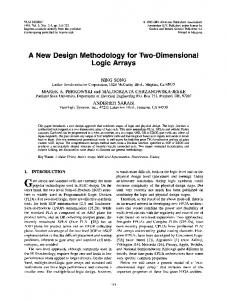
terned through the SiO2, using focused ion beam etching, with the multiple defect cavities designed into the PhC lattice by omitting selected holes. The pattern was then etched approximately 15 periods into the top DBR of the VCSEL using inductively coupled plasma reactive ion etching, thereby creating the air holes. A series of devices with a PhC lattice containing a 2 ⫻ 2 defect cavity pattern was fabricated. Parameters of the PhC lattice 共lattice constant, hole diameter, and hole depth兲 were chosen to give single-mode operation in a single-defect case.9 The lattice constant was 4.0 µm and the hole diameterto-lattice constant ratio was 0.7. Figure 1 shows examples of patterns that were etched into the devices. In Fig. 1共a兲, all holes in the PhC lattice were designed the same. In successive devices, the diameters of the four innermost holes, which are within the coupling regions between defect cavities, were reduced. Reduction in hole diameter is accompanied by a reduction in hole depth, relative to the other holes in the PhC lattice, due to reactive ion etch loading effects. Modifying these selected holes allows precise control of the effective index in the coupling regions, while positioning the optical loss to the location of the holes. Using this technique for controlling the effective index between defect cavities differs from etching trenches or reflectivity modulation to define array elements, because optical loss need not be introduced across the entire coupling region. In the series of fabricated devices shown in Fig. 1, the reduction of hole diameter and depth results in increasing the effective index in the coupling regions and reducing the optical loss.
FIG. 1. Examples of the hole patterns etched to create 2D arrays of defect cavities within PhC VCSELs. The lattice constant is 4.0 µm, and the diameter of each of the coupling region holes is 共a兲 2.8 µm, 共b兲 1.2 µm, and 共c兲 0.4 µm.
0003-6951/2005/86共20兲/201104/3/$22.50 86, 201104-1 © 2005 American Institute of Physics Downloaded 21 Nov 2005 to 130.126.136.168. Redistribution subject to AIP license or copyright, see http://apl.aip.org/apl/copyright.jsp
201104-2
Raftery et al.
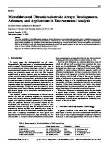
FIG. 2. 共a兲 Light—current characteristic for a device fabricated using the pattern shown in Fig. 1共b兲. Inset is the near-field image of the device operating just above threshold as a 2D coherently coupled PhC VCSEL.
Due to the geometry of the 2D triangular lattice used, there are asymmetries in the positioning of the 2 ⫻ 2 defect cavities. As is evident in Fig. 1共a兲, for a lattice constant a, the distance between the centers of the two top 共or bottom兲 defect cavities is 2a, which in this case is 8.0 µm. The distance between the centers of the two left 共or right兲 defect cavities is equal to 冑3a, which in this case is 6.9 µm. Additionally, there are asymmetries in the coupling regions between the defect cavities. The coupling regions between the two top 共or bottom兲 defect cavities has an air hole directly between the centers of the defect cavities, while the coupling regions between the two left 共or right兲 defect cavities has a gap. There is also a potential coupling region in the area at the center of the four defect cavities. As the diameter of the four holes in the coupling region is reduced, the unetched area within this central coupling region increases until it is a substantial fraction of the area of a defect cavity, and eventually results in an additional optical cavity. Figure 2 shows the light versus injection current characteristic for a PhC VCSEL fabricated using the pattern of Fig. 1共b兲. The inset is a near-field image of the device taken just above threshold 共meaning the injection current was approximately 1.1 times the threshold current value兲. This image shows four distinct lasing cavities, each confined within a defect cavity in the PhC lattice. The threshold current value for this device is 15 mA, approximately twice that of the broad-area oxide VCSEL prior to etching the PhC lattice. This increase is attributed to optical loss resulting from the etched holes. For the oxide VCSEL, the optical and electrical apertures coincide with the oxide aperture. For the device of Fig. 2, while the electrical aperture still coincides with the oxide aperture, there are now multiple optical apertures, defined by the defects in the PhC lattice. Each defect cavity has an area of approximately 50 m2, for a combined area of 200 m2, compared with 625 m2 for the oxide VCSEL without the PhC lattice. For this reason, much of the injected current passes through areas of the electrical aperture that do not coincide with the optical apertures, and subsequently does not contribute to stimulated emission. Designing the optical aperture to be closer in size to the electrical aperture has led to the reduction of threshold and increased output power in single-defect cavity devices.12 Figure 3 shows lasing spectra taken at currents from threshold to twice threshold for the device of Fig. 2. At threshold, the device shows a single dominant peak, which is
Appl. Phys. Lett. 86, 201104 共2005兲
FIG. 3. Spectral characteristics for the device of Fig. 2.
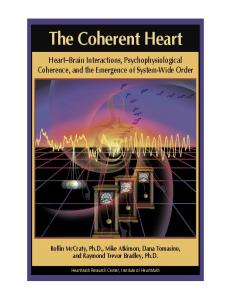
20 dB above the first higher-order mode. At 20 mA, the device is single mode, with 30 dB of side mode suppression. At higher currents, a second spectral peak is observed. Figures 4共a兲–4共c兲 shows far-field images 共to scale relative to each other兲 taken just above threshold from the PhC VCSELs fabricated using the patterns of Figs. 1共a兲–1共c兲, respectively. From these images, a determination of incoherent 共uncoupled兲 or coherent coupling between the 2D array of defect cavities can be made. Figures 4共a兲 and 4共c兲 are examples of devices which are not coherently coupled, with far fields indicative of the superposition of the Gaussian-type beams emitted from each of the operating defect cavities. Figure 4共b兲, however, shows a far-field image consistent with out-of-phase coherent coupling between the 2 ⫻ 2 array of defect cavities,13 and is from the device of Fig. 2. The outof-phase condition for the 2 ⫻ 2 array arises when a diagonal pair of defect cavities has the same phase, but is 180° outof-phase with the other diagonal pair of defect cavities.
FIG. 4. 共a兲–共c兲 Far-field images 共to scale relative to each other兲 taken just above threshold from the PhC VCSELs fabricated using the patterns shown in Figs. 1共a兲–1共c兲, respectively. Both 共a兲 and 共c兲 are examples of uncoupled devices with far fields indicative of the superposition of the Gaussian-type beams from each of the operating defect cavities, 共b兲 is indicative of out-ofphase coherent coupling, and is taken from the device of Fig. 2. 共d兲 Simulation of the far-field radiation pattern for the device of Fig. 2, operating out-of-phase coherently coupled. Downloaded 21 Nov 2005 to 130.126.136.168. Redistribution subject to AIP license or copyright, see http://apl.aip.org/apl/copyright.jsp
201104-3
Appl. Phys. Lett. 86, 201104 共2005兲
Raftery et al.
While the far-field image of Fig. 4共b兲 is an example of out-of-phase coherent coupling, there are features in the pattern that are not explained by simply having identical lasing defect cavities with an out-of-phase phase relationship. These features include the larger brighter lobes at the top right and bottom left, and an elliptical shape of each lobe. To investigate these features, simulations of coherent coupling for the PhC VCSEL design of Fig. 1共b兲 were performed using a beam propagation method. The PhC lattice of the air holes was placed within a background material with refractive index of 3.3, comparable to the effective index of the VCSEL within the oxide aperture. Circular Gaussian sources of identical shape and intensity were centered below each defect aperture having the fixed out-of-phase phase relationship described earlier, and the beams were allowed to propagate through the material for a distance of 5 µm. The simulation resulted in images which were generally consistent with the near field shown in the inset of Fig. 2 and with the far field of Fig. 4共b兲, though the far-field lobes were more symmetric, not exhibiting the features mentioned above. Examination of the measured near-field profiles, shown in the inset of Fig. 2, shows that the centroids of the lasing beams are not exactly centered within the defect apertures. By adding this into the simulation, a far-field image was calculated and is shown in Fig. 4共d兲. This image now exhibits larger brighter lobes at the top right and bottom left, and is in good agreement with the image of Fig. 4共b兲. Through further simulation, it was determined that the elliptical shape could be explained by increasing the intensity of one of the Gaussian sources relative to the other three. Such an occurrence could physically arise from greater current injection into one of the defect cavities caused by a slight misalignment of the oxide aperture and photonic crystal pattern. In summary, an approach for creating 2D arrays of coherently coupled vertically emitting laser cavities was demonstrated. It was shown that modifying the local index of
refraction in the coupling regions between defect cavities of a PhC VCSEL would result in out-of-phase coherent coupling between the 2 ⫻ 2 array of defect cavities. Simulations were conducted that are in good agreement with the measured data and provide additional insight into device operation. This work is supported by a National Science Foundation Graduate Research Fellowship, the United States Army under Award No. DAAD19-03-1-0299, and by the Defense Advanced Research Projects Agency under Award No. 317271-7830. The Center for Microanalysis of Materials, which is partially supported by U. S. Dept. of Energy, Grant No. DEFG02-91-ER45439, is acknowledged. 1
H.-J. Yoo, A. Scherer, J. P. Harbison, L. T. Florez, E. G. Paek, B. P. Van der Gaag, J. R. Hayes, A. Von Lehmen, E. Kapon, and Y.-S. Kwon, Appl. Phys. Lett. 56, 1198 共1990兲. 2 D. G. Deppe, J. P. van der Ziel, N. Chand, G. J. Zydzik, and S. N. G. Chu, Appl. Phys. Lett. 56, 2089 共1990兲. 3 M. Orenstein, E. Kapon, N. G. Stoffel, J. P. Harbison, L. T. Florenz, and J. Wullert, Appl. Phys. Lett. 58, 804 共1991兲. 4 M. E. Warren, P. L. Gourley, G. R. Hadley, G. A. Vawter, T. M. Brennan, B. E. Hammons, and K. L. Lear, Appl. Phys. Lett. 61, 1484 共1992兲. 5 D. K. Serkland, K. D. Choquette, G. R. Hadley, K. M. Geib, and A. A. Allerman, Appl. Phys. Lett. 75, 3754 共1999兲. 6 D. Zhou and L. J. Mawst, Appl. Phys. Lett. 77, 2307 共2000兲. 7 D.-S. Song, S.-H. Kim, H.-G. Park, C.-K. Kim, and Y.-H. Lee, Appl. Phys. Lett. 80, 3901 共2002兲. 8 N. Yokouchi, A. J. Danner, and K. D. Choquette, IEEE J. Sel. Top. Quantum Electron. 9, 1439 共2003兲. 9 A. J. Danner, J. J. Raftery, Jr., N. Yokouchi, and K. D. Choquette, Appl. Phys. Lett. 84, 1031 共2004兲. 10 A. J. Danner, J. C. Lee, J. J. Raftery, Jr., N. Yokouchi, and K. D. Choquette, Electron. Lett. 39, 1323 共2003兲. 11 K. D. Choquette, K. L. Lear, R. P. Schneider, Jr., K. M. Geib, J. J. Figiel, and R. Hull, IEEE Photonics Technol. Lett. 7, 1237 共1995兲. 12 A. J. Danner, J. J. Raftery, Jr., and K. D. Choquette, Proceedings of Conference on Lasers and Electro-Optics, San Francisco, Calif., May 16–21, 2004, Paper CTuP 共Control No. 1431兲. 13 G. R. Hadley, Opt. Lett. 15, 1215 共1990兲.
Downloaded 21 Nov 2005 to 130.126.136.168. Redistribution subject to AIP license or copyright, see http://apl.aip.org/apl/copyright.jsp