Paper published in: Machine Dynamics Problems, 2006, Vol. 30, No 3, 124-131
Collaborative Augmented Reality in CAD Design Marcin Januszka and Wojciech Moczulski Silesian University of Technology1
[email protected],
[email protected]
Abstract Design visualization in a more intuitive and clear way plays an important role in achieving proper understanding of the design. The technology of augmented reality (AR), as a kind of new user interface, should introduce completely new perspective for the computer aided design systems. Augmented reality mode for changing views of the model and completely understanding the model content is more efficient than traditional one. Despite the fact that it is still a new technology at a relatively initial state of development, augmented reality is very promising. This paper describes initial results of the research concerning an augmented reality system for CAD design. Application of an integrated CAD and AR system proposed by the authors should play an important role in achieving proper understanding of the model content and it will become an integral part of a standard design process.
Keywords: augmented reality, 3D CAD, VRML, visualization, design process.
1. Introduction The term Augmented Reality (AR) was first used in 1990 by researchers at Boeing, who developed an AR system to help workers in a Boeing factory put together wiring harnesses. The goal of Augmented Reality systems is to combine the interactive computer-generated world with an interactive real world in such a way that they appear as one environment. Unlike users of Virtual Reality (VR) systems, who are completely immersed in a virtual environment, users of AR systems see virtual objects and the real world coexisting in the same space. It is the goal of Augmented Reality to supplement reality rather than to replace it. The relationship between Virtual Reality and Augmented Reality was described by Paul Milgram, Haruo Takemura, Akira Utsumi, and Fumio Kishino in their Reality-Virtuality Continuum (Milgram et al., 1994). Augmented Reality occupies that place in the 1
Department of Fundamentals of Machinery Design.
2
M. Januszka, W. Moczulski
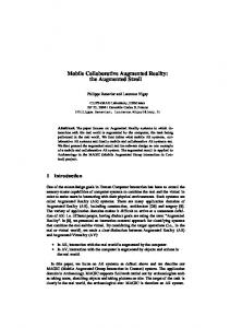
continuum where virtual objects are immersed into a predominantly real world environment (Fig. 1).
Fig. 1. Reality-Virtuality Continuum (Milgram et al., 1994)
We see prospects for AR in many aspects of our everyday lives. At present we are in early stage of exploring one such example of a potential new application domain for AR namely CAD design. Our conception of AR system allows integrating Computer Aided Design with AR technology and helps the users to comprehend this area more effectively by letting them visualize the design in a more intuitive and clear way.
2. The research problem Our AR system is inspired by the work of P. Dunston, M. Bilinghurst, Y. Luo, and B. Hampson. Their experimental prototype of ARCAD system allows designing some CAD model pipe layout for a new building with the ability to visualize the CAD design in augmented reality modes (Dunston et al., 2000). Our system like the ARCAD system allows integrating CAD and AR systems, but in different domain namely machinery design. There are still some technological problems to solve in AR technology. In the native literature there is not much information about application of AR technology. By this reason development of AR technology especially in CAD domain arouses our interest. Thuse we do hope that someday AR will be integral part of our everyday life.
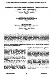
3. Conception of AR system Our research is focused on an augmented reality system consisted of the following components (Fig. 2) (Dunston et al., 2002): a computer running Dassault Systemes CATIA V5R16 (modeling software) and augmented reality viewing software (AR interface), an optical or video head mounted display (HMD) integrated with camera, the VRML (Virtual Reality Modeling Language) model database and CATPart (3D models from CATIA) model database, printed catalog of standard parts represented by markers.
Collaborative Augmented Reality in CAD Design
3
Fig. 2. Components of AR CAD system under development
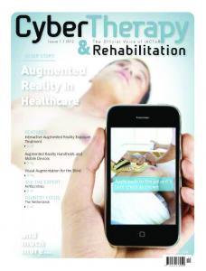
This system enables the user to easily view the model from any perspective. AR mode for changing views of the model and completely understanding the model content is more efficient than the traditional one. The most important and difficult part of augmented reality system proposed by us is software. The AR software allows the user to see virtual 3D models superimposed on the real world. We base on free augmented reality tracking library called ARToolKit (from HIT Lab) with LibVRML97 parser for reading and viewing VRML files. ARToolKit is a software library that uses computer vision techniques to precisely overlay VRML models onto the real world. For that purpose software uses markers. Each marker shows a different digitally encoded pattern on it, so that unique identification of each marker is possible. In our conception the markers are printed on the cards of the catalog. We can compute the user’s head location as soon as the given marker is tracked by the optical tracking system. The result is a view of the real world with 3D VRML models overlaid exactly on the card position and orientation. The process of video-based marker detection and overlay of virtual objects proceeds as follows (Fig. 3): 1. The video camera captures video of the real world and sends it to the computer. 2. The live video image is converted into a binary image based on a lighting threshold value. 3. Each video frame is searched by AR software for square regions (in perspective quadrangle regions). ARToolKit finds all the squares in the binary image, many of which are not the tracked markers. 4. For each square, the digitally encoded pattern inside the square is captured and matched against some pre-trained pattern templates. If there were a match, then ARToolKit found one of the AR tracking markers. 5. AR software uses the known square size and pattern orientation to calculate the position and orientation of the real video camera relative to the marker (Fig. 4).
4
M. Januszka, W. Moczulski
A transformation matrix Tcm (equation 1) is filled in with the video camera real world coordinates relative to the marker. This matrix is then used to set the position of the virtual camera coordinates. 6. Since the virtual and real camera coordinates are the same a VRML 3D model is precisely overlaid on the real square marker. The final output is displayed in the head-mounted display (HMD).
Fig. 3. The process of video-based marker detection and overlay of virtual objects (HITLab)
Collaborative Augmented Reality in CAD Design
X c V11 V12 V13 W x X m X m X m Y V Y W3 x1 Ym c 21 V22 V23 W y Ym V3 x3 m T cm Z c V31 V32 V33 W z Z m 0 0 0 Zm 1 Z m 0 0 1 1 1 0 1 1
5
(1)
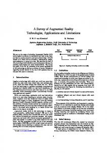
where: Xm, Ym, Zm – marker coordinates, Xc, Yc, Zc – camera coordinates, V33 – rotation component, W31 – translation component.
Camera Screen Coordinates
Camera Coordinates (Xc, Yc, Zc)
(xc, yc)
Marker Square
A Marker Coordinates (Xm, Ym, Zm)
Fig. 4. The relationship between marker coordinates and the camera coordinates, estimated by image analysis (Kato et al., 1999)
To see 3D VRML models on the cards the user needs a video or optical HMD display connected to the computer by a cable or wireless. In video HMD, virtual objects are superimposed on a live video image of the real world from camera. In this case the image is not stereographic. In optical HMD, virtual objects are shown directly on the real world by using a see-through display. In this case, the user can see the real world directly and virtual images can be stereoscopic. The user wears a HMD with a video camera attached, so when she/he looks at the tracking card through the HMD a virtual object is seen on the card (Fig. 5). A designer can pick up the catalog and manually manipulate the model for an inspection.
6
M. Januszka, W. Moczulski
Fig. 5. An augmented reality body overlaid on a tracking card using ARToolKit (image seen through HMD)
In our conception of AR system the user with HMD on head sits in front of a computer (Fig. 6). Moreover, a catalog with cards to be tracked is necessary. The user looks over the catalog with standard parts (for example rolling bearings) and by changing pages can preview all parts. When the user chooses the best fitting part, she/he can select also virtual “EXPORT” button. Having selected the “EXPORT” button, the designer in the CATIA’s workplane can see the imported part (Fig. 7c). After this the user can go back to modeling in CATIA or repeat the procedure for another part (Fig. 7d).
Fig. 6. Example of setup for designer using our AR system
Collaborative Augmented Reality in CAD Design
7
Fig. 7. Stages of a work with our AR system
4. Conclusion and future work In the future one of potential applications for the AR system proposed by us can be its application in the design session for example in brainstorming. In the design session of the future several designers sit around a table examining projects they are about to design. Through the HMD displays they can see each other and in the midst of the table they can see a three-dimensional virtual image of their CAD models. The image is exactly aligned over the real world so the designers are free to move around the table and examine it from any viewpoint. Each person has their own viewpoint to the model. They are also free to interact with the model in real time, adding or deleting parts etc. This is only one of many applications for our AR system and AR technology. There are also many other potential applications for augmented reality. There are still some technological problems to solve, but for industrial partners to be interested in investing into this technology its possible benefit and its integration into the whole company has to be visible. This paper presented the major challenges and the vision of how the final AR system for CAD design will be used. We show how it is possible to use augmented reality technology in CAD design. Maybe someday it will become an integral part of
8
M. Januszka, W. Moczulski
a standard design process. Future work will pursue confirmation of AR benefits for design model perception for users.
References Dunston, P. S., Billinghurst, M., Luo, Y., Hampson, B., 2000, Virtual visualization for the mechanical trade, 17th International Symposium on Automated and Robotics in Construction (ISARC 2000), National Taiwan University, 1131–1136. Dunston, P. S., Wang, X., Billinghurst, M., Hampson, B., 2002, Mixed Reality benefits for design perception, 19 th International Symposium on Automation and Robotics Construction (ISARC 2002), NIST, Gaithersburg, MD, 191–196. Kato, H., Billinghurst, M., 1999, Marker Tracking and HMD Calibration for a videobased Augmented Reality Conferencing System, in: Proceedings of the 2nd International Workshop on Augmented Reality (IWAR 99). Milgram, P., Takemura, H., Utsumi, A., Kishino, F., 1994, Augmented reality: a class of displays on the reality-virtuality continuum, SPIE, Telemanipulator and Telepresence Technologies, 2351. The Human Interface Technology Laboratory (HITLab) at the University of Washington; URL: http://www.hitl.washington.edu/research/shared_space/