of collimator hole shape and orientation as well as collimator and detector penetration. Equations for spatial resolution are derived for NaI and CZT based ...
Collimator Spatial Resolution H. Wieczorek, A. Goedicke, F. Edström, C. Degenhardt, H. Botterweck, and R. Bippus
Abstract-- Pixellated detectors based on cadmium-zinc telluride (CZT) are a promising alternative to NaI-based SPECT cameras. The performance of either system is quantitatively described in terms of resolution and sensitivity. This investigation is based on an analytical model published earlier, describing SPECT collimators according to the NEMA definitions of planar sensitivity and system spatial resolution without scatter. We have extended the model to include the effect of collimator hole shape and orientation as well as collimator and detector penetration. Equations for spatial resolution are derived for NaI and CZT based SPECT systems with hexagonal, round or square parallel-hole collimators and with pinhole collimators. Standard equations for spatial resolution are valid only for square hole collimators along one of the detector axes. In any other direction, spatial resolution is higher. The exact values depend on the hole shape and on the ratio of object-detector distance to collimator length. For pixellated pinhole detectors, similar corrections depending on the ratio of detector pixel size to the diameter of a point source projected on the detector apply. In scintillation cameras, spatial resolution is not only influenced by the average absorption depth in the scintillator, but it is strongly affected by the parallax effect of the collimator hole. Spatial resolution is therefore lower than usually thought. We present a model that describes the performance of current SPECT collimators and permits to optimize future detector systems for high image quality. I.
INTRODUCTION
Photon Emission Computed Tomography has been Single based for some decades on thallium doped sodium iodide scintillator plates. The development of this technology had started in 1956 with Hal Anger's first scintillation camera, built from a four inch NaI:Tl plate and seven photomultipliers. Their signals were combined and adjusted by a signal matrix circuit that allowed retrieving the position in the scintillator plate where every single gamma photon had been absorbed [1]. Planar images were obtained by pinhole collimators and, later, by parallel-hole collimators [2]. The technology used in current SPECT systems is well established, but there are a number of inherent restrictions: First, the low energy resolution of 9-10% at 140 keV energy Manuscript received October 26, 2005. Herfried Wieczorek, Andreas Goedicke, Carsten Degenhardt, Henrik Botterweck and Rolf Bippus are with Philips Research Laboratories, 52066 Aachen, Germany (telephone: +49-241-6003-241, e-mail: herfried.wieczorek @philips.com). Fredrik Edström is with Royal Institute of Technology, Stockholm, Sweden.
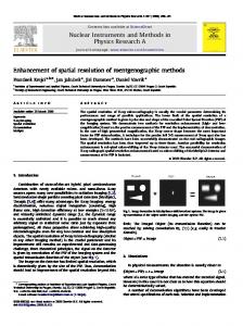
for NaI:Tl cameras, second, the uncertainty in Anger's algorithm, resulting in an intrinsic spatial resolution of 3-4 mm for standard gamma cameras, and third, the count rate limitation, caused by the large detector area needed for readout of single gamma photons. Due to these constraints, cameras with high system efficiency, high spatial resolution and high energy resolution are not yet available. Solid-state detectors based on cadmium-zinc telluride (CZT) have been proposed as the material of choice for new SPECT cameras, providing an energy resolution of 3-6% at 140 keV and high count rates [3]. A number of publications on CZT based SPECT systems are available, relying either on parallelhole collimation or on pinhole related concepts [4]-[6]. This is still work in progress. Pixellated solid-state detectors are described in terms of system efficiency and spatial resolution, the same parameters that are used to evaluate scintillation cameras. The underlying theory can be used for system optimization [7]. The main item that has to be considered for solid-state detectors is the pixellated readout associated with a discrete sampling scheme, in contrast to the analog readout of scintillation cameras. Additionally, the properties of the detector materials and penetration effects have to be taken into account. In this paper we extend our analytical collimator model to describe the spatial resolution of pixellated as well as continuous detectors. The angular dependent spatial resolution of parallel-hole detectors with different hole shape is calculated, and correction factors for the average spatial resolution of parallel-hole and pinhole detectors are derived. Basic differences in the spatial resolution achievable by Anger cameras and by pixellated detectors are revealed when penetration effects are taken into account. II. ANALYTICAL MODEL Classical theory describes collimator performance by a radioactive point source whose radiation is projected through the collimator holes and absorbed in the detector. Due to the shadowing effect of the collimator septa, the amount of radiation that passes through a single collimator hole depends on the exact source position relative to the position of the hole. This space variance of the point source response function makes the evaluation of collimator efficiency and spatial resolution difficult (Fig. 1). The analysis is usually simplified by assuming that the collimator is moving laterally between object and detector during the entire exposure time [2].
Collimator efficiency is calculated as the part of the radiation from a source, perpendicularly above and at a certain distance from a single collimator hole, that irradiates the open detector area of one pixel (normalized solid angle), multiplied by the average area in the object plane that is seen from any point on the detector pixel (region seen), and normalized by the area of the object plane equivalent to one pixel on the detector (voxel area) (Fig. 2). Details have been published before [7]. From this analytical model we get the geometric efficiency of a parallel-hole collimator with square holes,
E=
Fig. 1: Classical description of parallel-hole collimator. Black areas show illuminated parts of detector, black points give the signal height for analog and pixellated detectors. Digital sampling is at a location different from analog sampling. The point source response function is strongly space variant.
Fig. 2: Definition of geometric collimator efficiency based on the single pixel response function. A parallel-hole collimator is described by pixel diameter D, pixel pitch p and septa length L (left side), a pinhole collimator by hole diameter D, pixel size p and collimator-detector distance L (right side). The angle of incidence is β. The object-collimator distance is given by z and the object-detector distance is defined as z' = z+L.
4πL2 p 2
,
(1)
with different pre-factors for round or hexagonal hole shape [7]. For a round pinhole in the far field, the same analysis gives the equation E = D 2 / 16 z 2 ⋅ cos 3 β where the angle of incidence β enters the equation both through the normalized solid angle and by the projection on the pixel area. We write the pinhole efficiency as E=
We use an alternative approach, an analysis based on the single pixel response function (SPRF), to evaluate the performance of pixellated detectors in terms of sensitivity and spatial resolution. Our method does not take the space variance of the point source response function into account, which is consistent with the standard sensitivity measurement. Detector sensitivity, defined as the number of counts in the energy window for a specific isotope, is measured with a homogeneous flat phantom in front of the detector. Theoretically, sensitivity is given as the product of the branching ratio of the isotope, the effective absorption in the detector plate, and the geometric collimator efficiency.
D2 D2
D2 2
m 2 ⋅ cos 3 β
16 L with the linear magnification factor m = L / z .
(2)
III. SPATIAL RESOLUTION Spatial resolution R is calculated as the full-width at halfmaximum (FWHM) of the single pixel response function for a point source in the object plane, integrated in one dimension. This definition is equivalent to the measurement of spatial resolution by a line phantom that is slightly tilted with respect to one of the detector axes, used for sampling the single pixel detector response function (Fig. 3).
Fig. 3: Measurement of spatial resolution by a line source tilted with respect to one of the detector axes. Inset shows sampling of one-dimensional SPRF by pixels on left side (full circles) and right side of picture (open circles).
A. Baseline Spatial Resolution For every detector pixel, the measured signal depends on the exact position of the line source with respect to the collimator hole. When the line source is directly above the open part of the collimator hole, the signal is constant and independent of the exact source position, while a lateral source position results in a lower signal on that detector pixel (Figs. 3 and 4). In case of a parallel-hole detector the flat part of the SPRF has width D and the slopes have length Dz / L on either side. The FWHM of the response function is equal to the sum of these values, Dz ' / L . For a pinhole detector the width of the central part of the SPRF is different from the pinhole diameter D. The length of the slope is given by pz / L , and the sum of the width of
central part and slope is Dz ' / L (Fig. 4). The baseline spatial resolution for both detector concepts is therefore given by z' R=D . (3) L This is, however, a one-dimension analysis, valid for square hole or square pinhole detectors with the line source oriented parallel to one of the detector axes.
Fig. 5: Angular dependence of spatial resolution for square collimator holes. Simulation results for pixellated detector with D = 1.71 mm, L = 45 mm, and z = 0 mm, 50 mm, 100 mm, and 150 mm (from innermost to outmost curve).
For hexagonal holes there is hardly any angular spatial resolution dependence, and for round holes it is of course absent. For this latter case the SPRF can be calculated analytically. Integration in one dimension gives a pre-factor that has to be added to the baseline equation (3), resulting in the general equation for spatial resolution: z' R = ρ⋅D . (4) L The resolution correction factor ρ is a function of the ratio z ' / L , of the hole shape and, except for round holes, of the angle with respect to the detector axes. We define the angular average of spatial resolution as a measure of collimator performance. Fig. 6 shows the result of ray tracing calculations for square, hexagonal and round holes and for different values of the ratio z ' / L .
Fig. 4: Definition of collimator spatial resolution for parallel-hole (left side) and pinhole detector (right side). Spatial resolution R in one dimension is defined as the FWHM of the single pixel response function.
B. Angular Resolution Dependence Generally, the collimator hole shape and the orientation with respect to the detector axes have to be taken into account when spatial resolution is measured. This is done by integration of the SPRF in the direction along the line source (Fig. 3). In case of square collimator holes, the SPRF is orthogonal in x and y direction so that (3) is valid if the line source is parallel to one of the detector axes. For any other direction spatial resolution is higher. This angular resolution dependence is shown in Fig. 5. Spatial resolution is strongly non-isotropic when the object is near the collimator (innermost curve), while for larger source-collimator distance z the anisotropy is less enhanced (outmost curve).
Fig. 6: Angular average of the correction factor ρ for spatial resolution of parallel-hole collimators with different hole shape.
For all three collimator shapes calculated, the correction factor ρ is smaller than one and spatial resolution is higher than given by the baseline equation for square holes (3), especially in the near field. For square holes a value of 0.895 is obtained when the source is in close contact with the collimator surface. For round and hexagonal holes, minima with respective values of 0.813 and 0.854 are reached when z ' / L is in the range of 1.8 to 1.9. The minimum correction value for round holes is nearly equal to the value of 0.808 that had earlier been given as a general correction factor for round holes [8].
Fig. 8: Efficiency and resolution of parallel-hole detector with penetration. The SPRF is widened for continuous detectors due to the parallax effect of the hole. The distance between the bottom collimator surface and the average absorption depth in the detector is defined as b.
E=
D2
D2
4πL2eff p 2
and spatial resolution for pixellated detectors, z eff ' . R = ρ⋅D Leff
Fig. 7: Correction factor ρ for spatial resolution of a pinhole detector with round pinhole and square detector pixels.
For pinhole collimators with round pinholes and square detector pixels the correction factor ρ is a function of the pixel size p divided by the size of the point source projected through the pinhole onto the detector, D ⋅ z ' / z (Fig. 7). The minimum value of ρ is 0.813, equal to the value for round parallel holes.
(5)
(6)
For pinhole detectors with tapered pinholes the same simple approximation is applied to penetration in the pinhole edge. In a one-dimensional analysis the effective pinhole diameter is calculated as Deff = D + 1 / µ ⋅ tan(α / 2) with the tapering angle α (Fig. 9). Pinhole efficiency is Deff 2
m 2 ⋅ cos 3 β 16 L2 and spatial resolution is given by z' R = ρ ⋅ Deff . L E=
(7)
(8)
C. Penetration Effects Our analysis so far assumed perfect absorption of gamma quanta in the collimator septa. Efficiency and spatial resolution are, however, influenced by partial penetration of the septa. This effect may approximately be accounted for by assuming an effective septa length that is reduced by 1 / µ on either side, where µ is the linear attenuation coefficient of the collimator. For lead collimators, 1 / µ = 0.4 mm at 140.5 keV. Calculating the efficiency of parallel-hole detectors, we see that all gamma quanta reaching the effective lower collimator surface, 1 / µ above the bottom of the collimator, hit the detector surface (Fig. 8). Defining the parameters z eff = z + 1 / µ , the effective septa length Leff = L − 2 / µ , and z eff ' = z eff + Leff = z '−1 / µ we get the geometric efficiency
Fig. 9: Spatial resolution in a tapered pinhole detector with penetration: Definition of effective diameter (left side) and spatial resolution (right side).
Anger's approximation and an analytic solution of this problem can be found in a recent study on the effective pinhole diameter [9]. Besides these penetration effects, the dependence on the angle of incidence, the resolution correction factor ρ , and the effect of scatter in the pinhole edge have to be considered when spatial resolution of a pinhole detector is calculated. D. Continuous Detectors For continuous detectors the analysis of spatial resolution is further modified. In the derivation of (6) and (8) we assumed that the sampling of the single pixel response function is done in the center of the collimator hole, which is correct for a pixellated detector with registered collimator. In case of a continuous detector like the scintillator based Anger camera, however, sampling takes place at the location where the gamma quanta are absorbed. For the flat central part of the SPRF this location is identical to the center of the collimator hole when we take the average over a large number of absorbed gamma quanta. When the source position is outside the region above the collimator hole, the gamma quanta hit the detector at a position away from the center of the hole (Fig. 8). This is a parallax effect similar to pinhole collimation. In terms of the single pixel response function, this is equivalent to a widening of its slope. Its length, D ⋅ z eff / Leff for pixellated detectors, is increased by D ⋅ ( L / 2 + b) / Leff
for continuous detectors.
When we add these terms to the pixel diameter D we get the geometric resolution of a continuous detector with parallel-hole collimator, z '+b 1 R = ρ ⋅ D( + ). (9) Leff 2 The first part of this equation is known, but the extra term ρ ⋅ D / 2 , caused by the parallax effect, shows that the spatial resolution of scintillator-based cameras is lower than generally thought. The intrinsic detector resolution Ri of continuous detectors
IV. CONCLUSIONS We have analyzed different collimator concepts for pixellated and continuous SPECT detectors, aiming to find the best-suited concepts for high efficiency solid-state detectors. Spatial resolution, usually described by the same baseline equation for all detector concepts, is generally higher when it is measured in any direction different from the detector axes. Correction factors for the angular average of spatial resolution are provided for square, hexagonal and round holes. For parallel-hole collimators, we have found that these correction factors depend on the ratio of object-detector distance and collimator height, while for pinhole collimation there is a dependence on the ratio of detector pixel size and the diameter of a point source projected on the detector. Penetration in the collimator septa is taken into account by definition of an effective septa length and object-detector distance for parallel-hole collimators and by an effective hole diameter for pinhole detectors. For continuous detectors, the parallax effect of the collimator holes requires a further correction that adds to the standard equation describing spatial resolution. This parallax effect, combined with the intrinsic spatial resolution of the Anger camera, is the reason for the generally lower spatial resolution of scintillator-based cameras in comparison to solid-state detectors. Based on our analytical model, a finite optimization of SPECT collimators is possible. A further increase in image quality will be achieved by making use of the higher spatial resolution of pixellated detectors. The main advantage of solidstate detectors, however, lies in their excellent energy resolution, enabling further scatter reduction and multi-isotope imaging. V. REFERENCES [1] [2] [3]
is usually added in squares to the geometric resolution. In case of focused collimators, e.g. for a fan beam detector, Ri is
[4]
divided by the magnification factor m. The spatial resolution of a continuous parallel-hole detector is thus given by
[5]
2
2 z '+b 1 R R = ρD ( + ) + i . (10) Leff 2 m For pinhole detectors the parallax effect is an intrinsic collimator property. The average absorption depth is taken into account by adding the parameter b to the collimator-detector distance L (Fig. 9). The resulting spatial resolution is 2
2
z '+b R R = ρDeff ( ) + i . L+b m
(11)
[6]
[7]
[8]
[9]
H.O. Anger, "Scintillation camera", Rev. Sci. Instrum., vol. 29, pp. 2733, 1958 H.O. Anger, "Scintillation camera with multichannel collimators", J. Nuclear Medicine 5, pp. 515-531, 1964 E. Raiskin, J. F. Butler, "CdTe low level gamma detectors based on a new crystal growth method,” IEEE Trans. Nucl. Sci., vol. 35, pp. 81-84, Feb. 1988. C. Scheiber, "New developments in clinical applications of CdTe and CdZnTe detectors", Nucl. Instr. and Meth. in Phys. Res. A 380, pp. 385391, 1996 J. F. Butler, C. L. Lingren, S. J. Friesenhahn, W. L. Ashburn, R. L. Conwell, F. L. Augustine, et al, “CdZnTe solid-state gamma camera,” IEEE Trans. Nucl. Sci., vol. 45, pp. 359-363, June 1998. M. Petrillo, J. Ye, J. Vesel, L. Shao, H. Wieczorek, and A. Goedicke, "Imaging performance of tiled solid state detectors", presented at IEEE MIC 2004, Rome, Oct. 2004 H. Wieczorek, A. Goedicke, L. Shao, M. Petrillo, J. Ye, and J. Vesel, "Analytical model for pixellated SPECT detector concepts", presented at IEEE MIC 2004, Rome, Oct. 2004 H. H. Barrett, W. Swindell, "Radiological imaging: theory of image formation, detection, and processing", vols. I and II, Academic Press, New York 1981 R. Accorsi, S. D. Metzler, "Analytic determination of the resolutionequivalent effective diameter of a pinhole collimator", IEEE Trans. Medical Imaging, vol. 23, pp. 750-763, June 2004.