Consist of input/output variables and logic gates. ▫ Sequential Circuits. ▫.
Outputs are determined from the present inputs and the state of the storage
elements.
Now we have gone through every part of combinational logic system design. ...
Physical design transforms the circuit graph into a layout (or blueprint) for ...
full-adder. In circuit development two half-adders can be employed to form a .... A
combinational circuit of full-subtractor performs the operation of subtraction of.
Common Combinational Logic Circuits. • Adders. – Subtraction typically via 2s
complement addition. • Multiplexers. – N control signals select 1 of up to 2N
inputs ...
Modeling Combinational Logic. Circuits. Debdeep Mukhopadhyay. IIT Madras ...
Circuit Structure. Second circuit has a shorter critical delay (longest path delay)!
CSZ Computer Systems note 9. Combinational Logic Circuits. Computer systems
are built from binary digital logic circuits: circuits in which each signal has only ...
two-level logic and canonical forms realized with NANDs and NORs. ❑ multi-
level logic, converting to NAND and NOR networks. ▫ Time behavior of circuits.
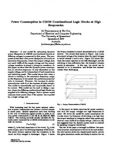
probability p,â we mean âwith a probability p of being at log- ical one.â When we say âa circuit,â we mean a combinational circuit built with logic gates. Example 1.
[7] Anantha P. Chandrakasan, Samuel Sheng & Robert W. Broder- sen, \Low-Power CMOS Digital Design," IEEE Journal Of. Solid-State Circuits.Vol. 27(April ...
sequential logic circuit the outputs depend on the inputs plus its history; i.e. it has
memory. ... design a 3-to-8 decoder using combinational logic circuits. II.
CS61c: Representations of Combinational Logic Circuits. J. Wawrzynek. October
12, 2007. 1 Introduction. In the previous lecture we looked at the internal details ...
In this paper, we limit our focus to combinational logic circuits, which contain ... Koza (1992) has used genetic programming to design combinational circuits.
January 30, 2012. ECE 152A - Digital Design Principles. 2. Reading Assignment.
▫ Brown and Vranesic. ❑ 2 Introduction to Logic Circuits. ▫ 2.10 Introduction to ...
The foundations for the design of digital logic circuits were established in the ...
The approach taken is to examine the tasks that a combinational logic cir-.
Jerry Chih-Yuan Yang. Giovanni De Micheli. Technical Report: CSL-TR-93-584. September 1993. This research is sponsored by NSF and DEC under a PYI ...
One method to reduce the circuit complexity of static CMOS. Here, the logic
function is built in the PDN and used in combination with a simple load device.
The aims of the course are to: • Familiarize students with combinational and se-
quential digital logic circuits, the analogue-digital interface, and the hardware ...
Combinational logic circuits (circuits without a memory): Combinational switching
networks whose outputs depend only on the current inputs. Sequential logic ...
Exact Functional Fault Collapsing in Combinational Logic Circuits. Abstract. Fault
equivalence is an essential concept in digital VLSI de- sign with significance in ...
rives at a combinational output node, but is not latched because of the clock. Qcritical of a ..... [2] Shivakumar P, Kistler M, Keckler S, et al. Modeling the effect of.
3 The multiplicative complexity of a function is the number of GF(2) multiplications ... linear components of several candidates to the SHA-3 competition. The.
the given probabilities can be duplicated and whether there is free- dom to ... zeros and ones; they are processed by ordinary logic gates, such as. AND and OR.
Jul 6, 2017 - MSc Engineering Degree in Information and. Communication Technology (ICT) at Mawlana. Bhashani Science and Technology University,.
1. ECE 438 Spring 2004. Assignment #5 – Combinational Logic Gates in CMOS.
Chapter 6, Digital Integrated Circuits 2 nd. 1) Implement the equation X = ((A' + ...
Combinational Logic. Static CMOS Circuit. At every point in time (except during
the switching transients) each gate output is connected to either. VDD. orVss.
Static CMOS Circuit At every point in time (except during the switching transients) each gate output is connected to either VDD or Vss via a low-resistive path. The outputs of the gates assume at all times the value of the Boolean function, implemented by the circuit (ignoring, once again, the transient effects during switching periods). This is in contrast to the dynamic circuit class, which relies on temporary storage of signal values on the capacitance of high impedance circuit nodes. Digital Integrated Circuits
NMOS Transistors in Series/Parallel Connection Transistors can be thought as a switch controlled by its gate signal NMOS switch closes when switch control input is high A
B
X
Y
Y = X if A and B
A
X
B
Y
Y = X if A OR B
NMOS Transistors pass a “strong” 0 but a “weak” 1 Digital Integrated Circuits
High noise margins: VOH and VOL are at VDD and GND, respectively. No static power consumption: There never exists a direct path between VDD and VSS (GND) in steady-state mode. Comparable rise and fall times: (under the appropriate scaling conditions)
Properties of Complementary CMOS Gates High noise margins: VOH and VOL are at VDD and GND, respectively. No static power consumption: There never exists a direct path between VDD and VSS (GND) in steady-state mode. Comparable rise and fall times: (under the appropriate scaling conditions)
2. Determine “Worst Case Input” transition (Delay depends on input values) 3. Example: tpLH for 2input NAND - Worst case when only ONE PMOS Pulls up the output node - For 2 PMOS devices in parallel, the resistance is lower t pLH = 0.69Rp CL
2-input NAND
4. Example: tpHL for 2input NAND - Worst case : TWO NMOS in series t pHL = 0.69(2R n)CL
Domino Logic - Characteristics •Only non-inverting logic •Very fast - Only 1->0 transitions at input of inverter move VM upwards by increasing PMOS • Adding level restorer reduces leakage and charge redistribution problems • Optimize inverter for fan-out