Jun 4, 2018 - (patrick.huebner, martin.weinmann, markus.hillemann, boris.jutzi, ... of application for AR systems backed by this new wave of pow-.
The International Archives of the Photogrammetry, Remote Sensing and Spatial Information Sciences, Volume XLII-2, 2018 ISPRS TC II Mid-term Symposium “Towards Photogrammetry 2020”, 4–7 June 2018, Riva del Garda, Italy
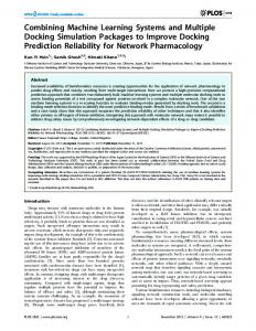
COMBINING INDEPENDENT VISUALIZATION AND TRACKING SYSTEMS FOR AUGMENTED REALITY P. Hübner, M. Weinmann, M. Hillemann, B. Jutzi, S. Wursthorn Institute of Photogrammetry and Remote Sensing, Karlsruhe Institute of Technology (KIT), Karlsruhe, Germany (patrick.huebner, martin.weinmann, markus.hillemann, boris.jutzi, sven.wursthorn)@kit.edu Commission II, WG II/4 KEY WORDS: augmented reality, pose estimation, tracking, calibration, visualization
ABSTRACT: The basic requirement for the successful deployment of a mobile augmented reality application is a reliable tracking system with high accuracy. Recently, a helmet-based inside-out tracking system which meets this demand has been proposed for self-localization in buildings. To realize an augmented reality application based on this tracking system, a display has to be added for visualization purposes. Therefore, the relative pose of this visualization platform with respect to the helmet has to be tracked. In the case of hand-held visualization platforms like smartphones or tablets, this can be achieved by means of image-based tracking methods like marker-based or model-based tracking. In this paper, we present two marker-based methods for tracking the relative pose between the helmet-based tracking system and a tablet-based visualization system. Both methods were implemented and comparatively evaluated in terms of tracking accuracy. Our results show that mobile inside-out tracking systems without integrated displays can easily be supplemented with a hand-held tablet as visualization device for augmented reality purposes.
1. INTRODUCTION In recent years, augmented reality (AR) has experienced an upswing in popularity initiated by the emergence of capable AR technology like the Microsoft HoloLens (Microsoft, 2018) or efficient tracking frameworks for off-the-shelf tablets and smartphones like ARKit (Apple, 2018) or ARCore (Google, 2018). Possible fields of application for AR systems backed by this new wave of powerful tracking technology range from the entertainment industry, mechanical assembly guidance (Wang et al., 2016) and medical applications (Guha et al., 2017) to the construction industry (Behzadi, 2016). Here, the on-site visualization of location-specific virtual content like BIM (Building Information Modeling) data has the potential to enhance efficiency in every stage of the building life cycle from planning and construction to facility management and maintenance (Chu et al., 2018; Ren et al., 2016). In this context of AR-based access to BIM data, the mobile helmetbased tracking system presented by Urban et al. (2013) meets the demand for a reliable tracking system in indoor environments put forward by Kopsida and Brilakis (2016), where the proposed system does not rely on the physical installation of artificial markers in the application area for localization. The aforementioned helmet system provides model-based self-localization in building environments by means of untextured CAD models and then tracks its pose via a SLAM algorithm for fisheye cameras (Urban et al., 2016; Breunig et al., 2017). Based on this tracking system, an AR system for building environments can be created by supplementing the helmet system at hand with a portable display like a smartphone or tablet. To handle this, the relative pose of the visualization platform with respect to the tracking system has to be known. This can be achieved by means of image-based tracking methods like marker-based or modelbased tracking. Here, the relative tracking between both systems has been realized as marker-based tracking. This is conceivable in both directions: the pose of the tablet can be tracked with the
cameras of the helmet system and vice versa. Both methods have been realized in the scope of our work. After briefly summarizing related work in Section 2, we present two marker-based methods for tracking the relative pose between the helmet-based tracking system and a tablet-based visualization system in Section 3. The necessary calibration steps and the evaluation procedure are summed up in Section 3 as well. In Section 4, the results of the evaluation of both proposed tracking methods are presented. After a detailed discussion of the findings in Section 5, we finish with concluding remarks and suggestions for future work in Section 6. 2. RELATED WORK The term augmented reality (AR) dates back to the year 1992 when it was first used by Caudell and Mizell (1992) to describe the superimposing of real objects with virtual, computer-generated content. Milgram and Kishino (1994) defined the term mixed reality covering a range of applications between the real world and complete virtual environments. Nevertheless, applications have already been proposed or realized much earlier, which today would be attributed to the augmented reality sector like e.g. the early head-mounted AR device presented by Sutherland (1968). In the subsequent years, the definition of AR was rendered more precisely, e.g. by Azuma (1997) who postulated real-time capabilities and interactivity as necessary criteria for augmented reality besides the combination of real and virtual content. Typical hardware platforms for mobile augmented reality applications are hand-held devices like smartphones or tablets and head-mounted devices (HMDs), often also called AR glasses or smart glasses. Both types of AR devices have their own specific advantages and disadvantages that have to be taken into account when choosing the optimal hardware platform for an intended mode of operation (Bach et al., 2018). Besides tablets or smart
This contribution has been peer-reviewed. https://doi.org/10.5194/isprs-archives-XLII-2-455-2018 | © Authors 2018. CC BY 4.0 License.
455
The International Archives of the Photogrammetry, Remote Sensing and Spatial Information Sciences, Volume XLII-2, 2018 ISPRS TC II Mid-term Symposium “Towards Photogrammetry 2020”, 4–7 June 2018, Riva del Garda, Italy
glasses, objects can be augmented with virtual models with the use of projectors (Kern et al., 2017). Typically, projector-based AR is used in prepared environments. When using smartphones or tablets, the environment is captured with the rear camera of the device and its image is shown on the built-in display that can be augmented with computer-generated 3D objects that have to be transformed into every camera frame. The user has to point the device at some object or place in order to see corresponding augmented information on the display. This kind of video-based augmentation is also known as the magic lens principle (Bier et al., 1993). Because of the high distribution of smartphones, magic lens is the most common AR principle today. Compared to HMDs, the major drawbacks of magic lenses are that users have to hold them in at least one hand and that the augmented scene is only visible on the display. The basic requirement for the successful deployment of any augmented reality application is a stable and reliable tracking system that provides the exterior orientation (pose) in real-time. Much of AR research ist focused on image-based tracking systems using one or more cameras. A good summary of image-based tracking methods that can be used for tracking an AR system is given by Marchand et al. (2016). The most basic principle for image-based tracking is the use of known planar targets (markers) like ArUco (Garrido-Jurado et al., 2014) or ARToolKit (Kato and Billinghurst, 1999). These solve for both relative pose estimation and event triggering with the help of a distinct ID on each marker. The preparation of environments with markers may be undesirable or even impossible. In this case, natural features like a set of interest points with local descriptors (keypoints) or known textures (Georgel et al., 2007) can be used as a replacement for markers if they are trained in advance. Mikolajczyk et al. (2004) or Weinmann (2013) give overviews of usable features. Whole images that are aligned at specific locations can be used as keyframes. Databases with keyframes can be used on larger environments or even outdoors (Arth et al., 2009). These solutions can be deployed on smartphones (Comport et al., 2006; Klein and Murray, 2009). Mobile AR frameworks use natural features in combination with data of an integrated inertial measurement unit for robust relative egomotion estimation with visual intertial odometry like ARKit (Apple, 2018) or within a SLAM solution (Google, 2018). Additionally, planes and ambient lighting conditions can be detected within the scene for seemlessly placing virtual objects with adapted rendering options into the real environment. If 3D models of the environment are available, these can be used for tracking. Reitmayr and Drummond (2006) use textured city models for a model-based tracking solution with edge features. Urban (2016) uses visible edges of untextured 3D building models for tracking. The initialization can be solved with the help of GNSS in outdoor environments. Urban et al. (2013) present a system that solves the initialization problem with a multi-fisheye camera system for indoor applications. For the evaluation of estimated trajectories resulting from tracking algorithms with respect to ground truth trajectories, Sturm et al. (2012) provide an implementation for the absolute trajtory error that has been proposed by the Rawseeds project (Ceriani et al., 2009).
Figure 1. The helmet-based tracking system proposed in (Urban, 2016) with an additional ArUco-Marker (Garrido-Jurado et al., 2014) from the perspective of the front camera of the hand-held tablet. 3. METHODOLOGY Utilizing a tablet for the visualization of virtual objects in the context of AR applications, the pose TW TB of the camera on the rear side of the tablet with respect to some world coordinate frame has to be known. In our case, this can be achieved by connecting the tablet geometrically to the aforementioned helmet system whose pose TW H can be considered as known because of its tracking capacities. By tracking the relative pose TH TB between the tablet back camera and the helmet, the tablet camera pose can be determined as: W H TW TB = TH TTB
(1)
Generally a pose TB A of a body A with respect to a coordinate frame B is represented by a 4 × 4 matrix that can be understood as a three-dimensional Euclidian transformation from the local coordinate frame of the respective object A to the coordinate frame B described in homogenous coordinates:
TB A =
�
RB A 0>
tB A 1
�
∈ R4×4
(2)
3×3 3 where RB is a rotation matrix and tB A ∈ R A ∈ R a threedimensional translation vector.
An easy way of determining this relative pose between the tablet and the helmet system consists in marker-based tracking. Hereby, a planar marker is observed by a camera whose pose relative to this marker can be determined by solving the homography transformation between the known geometry and dimensions of the used marker and its projective image captured by the camera. A wide range of software packages exists that enable the easy implementation of marker-based camera tracking in real-time with sufficient pose accuracy for augmented reality purposes. An example for such a marker-based tracking framework is ArUco (Garrido-Jurado et al., 2014) which has been used in our work. 3.1
Tablet-based tracking
Two basic strategies are conceivable for marker-based tracking of the relative pose between a tracking system and the visualization device. On the one hand, markers could be attached to the tracking platform itself, that are then observed by a camera mounted on the visualization device. This of course presumes that the visualization
This contribution has been peer-reviewed. https://doi.org/10.5194/isprs-archives-XLII-2-455-2018 | © Authors 2018. CC BY 4.0 License.
456
The International Archives of the Photogrammetry, Remote Sensing and Spatial Information Sciences, Volume XLII-2, 2018 ISPRS TC II Mid-term Symposium “Towards Photogrammetry 2020”, 4–7 June 2018, Riva del Garda, Italy
TH MH (calibrated)
x z y marker x f rame
helmet f rame
z y
f ront camera f rame z
H TM TF (tracked)
x x helmet z y f rame helmet x camera f rame
x x
y
back z camera f rame
y tablet(sideview)
Figure 2. Tracking the relative pose between tablet and helmet by observing an ArUco marker mounted on the helmet from the front camera of the tablet.
A schematic overview of this tablet-based version of our markerbased relative tracking method is depicted in Figure 2. Here, the relative pose TH MH of the ArUco marker attached to the helmet with respect to the local coordinate frame of the helmet as well as the relative pose TTTFB between the front-facing and the backfacing tablet cameras are assumed to be known and have to be calibrated beforehand. The used calibration procedure is discussed in Section 3.4. H TM TF
By using marker-based tracking, the pose of the user-facing camera on the front side of the tablet with respect to the ArUco marker on the helmet it is observing can easily be obtained. With this tracked pose and the calibrated poses mentioned above, the pose TH TB needed for Equation 1 can be determined according to: (3)
kerf
x ram
z
e
y
y
MT
C TH MT (tracked)
TTB x (calibrated)
OptiT rack cameras helmet f rame x
TH T
z
tablet f rame
x
y
z TO H
y y TO T
x z OptiT rack f rame Figure 4. Evaluation scheme: the pose of the helmet system and the tablet are tracked directly with OptiTrack while the pose of the tablet is additionally derived from the helmet pose via the respective relative tracking method. in this case as well as depicted schematically in Figure 3. In practice, however, a checkerboard pattern was used, as the ArUco framework used for marker tracking is not compatible with the projection model of the fisheye cameras mounted on the helmet. 3.3
3.2
mar
z
Figure 3. Tracking the relative pose between tablet and helmet by observing markers displayed on the tablet screen from the helmet cameras.
device is equipped with a camera in which the tracking platform with the marker is visible during operation. So in our case, where we use a head-mounted helmet-based tracking system and a handheld tablet as visualization device, the tablet has to be equipped with a camera on the front side above the screen that faces the user when looking at the tablet screen. This is the case with the tablet model we used. An image taken with this user-facing front camera of our tablet that depicts the helmet-based tracking system equipped with an ArUco marker is shown exemplarily in Figure 1.
TF H M TH TB = TM TTF TTB
z
tablet camera f rame
TH HC (calibrated)
TTTB F (calibrated)
Evaluation strategy
Helmet-based tracking
On the other hand, it is also conceivable to track the relative pose between the tablet and the helmet system in the opposite direction by observing the tablet with the fisheye cameras mounted on the helmet. In this case, the pose TH HC of the helmet camera used for marker tracking in the local coordinate frame of the helmet T and the relative pose TM TB between the tablet rear side camera and the marker depicted on the tablet screen have to be calibrated beforehand. The relative pose between the helmet and the tablet camera then results in: HC MT H TH TB = THC TMT TTB
(4)
Here, the markers used for marker-based tracking do not necessarily have to be attached physically but can be visualized directly on the tablet screen. Principally, ArUco markers could be used
For obtaining ground truth data for evaluation, the motion capture system OptiTrack (OptiTrack, 2018) was used. This outside-in multi-camera tracking system consists in our case of eight infrared cameras. Using OptiTrack to obtain ground truth data for the evaluation of tracking methods in the context of augmented reality has been done e.g. by Li et al. (2015). In our case, the helmet system as well as the tablet have been equipped with a rigid body consisting of three reflective sphere targets that can be tracked with the motion capture system. The poses of these rigid bodies have been calibrated relative to the cameras of the respective device. This way, we were able to track the poses of both devices in the coordinate frame of the motion capture system with high accuracy as ground truth used for the evaluation of the relative tracking accuracy. A schematic overview of this procedure is depicted in Figure 4: the tablet pose is obtained by deriving it from the helmet system
This contribution has been peer-reviewed. https://doi.org/10.5194/isprs-archives-XLII-2-455-2018 | © Authors 2018. CC BY 4.0 License.
457
The International Archives of the Photogrammetry, Remote Sensing and Spatial Information Sciences, Volume XLII-2, 2018 ISPRS TC II Mid-term Symposium “Towards Photogrammetry 2020”, 4–7 June 2018, Riva del Garda, Italy
pose by means of the respective relative tracking method while the helmet pose itself is tracked directly with the cameras of the motion capture system. Additionally, the reference pose of the tablet is also obtained in this way. By tracking the helmet pose directly with the motion capture system instead of using the helmet-based tracking system, it is possible to evaluate the proposed methods for combining visualization devices with arbitrary tracking systems independently from the accuracy of the mobile tracking system. 3.4
Calibration
For the practical realization of the presented marker-based trackingmethods for combining a tablet as visualization device with the helmet-based tracking system, a multitude of calibrations has to be conducted. Firstly, the inner orientation, i.e. the model of the camera projection, of all utilized cameras has to be determined. Both off-the-shelf webcams on the front and rear side of the tablet were calibrated by applying the standard OpenCV algorithm for perspective camera calibration proposed by Bouguet (2004) and Zhang (2000). The fisheye cameras on the helmet however were calibrated with the method presented by Urban et al. (2015), which uses a generalized camera model that is more convenient for fisheye cameras than the perspective model. This calibration of the inner orientation of the helmet cameras as well as the calibration of their respective relative poses to one another was already at hand and did not have to be repeated. For evaluation purposes (Section 3.3), rigid bodies respectively consisting of three reflective sphere markers that can be tracked with a motion capture system were mounted on the helmet as well as on the tablet. These rigid bodies were used to define the local coordinate frame of the helmet system used in this work and the local coordinate frame of the tablet as depicted in Figure 4. In both cases, the relative pose between the rigid body and cameras of the respective device it is attached to had to be determined. This was achieved via a two-step calibration procedure for calibrating the relative pose between a rigid body and an arbitrary camera which is briefly mentioned in (Hillemann and Jutzi, 2017) and is presented here in more detail. In the first step, a pattern like e.g. an ArUco marker is applied to a rigid board equipped with an own rigid body. The relative pose TB M between this marker and the board rigid body is calibrated by manually contacting the corners of the marker with another rigid body and thus determinO ing the marker pose TO M as well as the pose TB of the rigid body mounted on the board in the global coordinate frame defined by the motion capture system: O TB M = TB
−1
TO M
(5)
This calibrated marker board can then be used in the second calibration step to determine the relative pose TD C between a camera and a rigid body affixed to the camera device. This is depicted schematically in Figure 5. Here, the poses of the camera rigid O body and the marker board rigid body TO D and TB are directly tracked by the motion capture system, while the camera pose in the coordinate frame defined by the motion capture system TO C can be derived by: O B M TO C = T B TM TC
(6)
Here, TM C denotes the relative pose between the camera and the marker it observes, which can be obtained by means of markerbased tracking, while TB M is the pose between the marker and
the rigid body on its board which has been determined in the first calibration step. The relative pose TD C between the camera and its rigid body then results to: −1
O TD C = TD
TO C
(7)
More robust results are achieved when this procedure is not only applied once but multiple times while varying the camera pose relative to the marker board. The final pose TD C between the camera and its rigid body can then be derived e.g. by taking the mean or median pose from all resulting poses or by means of an optimization procedure. Hillemann and Jutzi (2017) for example used a Levenberg-Marquard optimization that minimizes the reprojection error. This procedure has been used to calibrate the helmet cameras relative to the rigid body mounted on the helmet and to calibrate front and rear camera of the tablet to its rigid body. In the case of the helmet, a checkerboard pattern was used instead of an ArUco marker. Furthermore, the respective poses of the tablet cameras relative to the rigid body on the tablet can be used to determine the relative pose between both cameras by: T TF R = TF
−1
TTR
(8)
Here, TTF denotes the pose of the tablet front camera in the local tablet coordinate frame defined by the rigid body affixed to the tablet and TTR the respective pose of the rear camera. 4. EXPERIMENTAL RESULTS Both proposed methods for relative pose estimation between tablet and helmet system have been evaluated quantitatively against ground truth data derived by the motion capture system OptiTrack as detailed in Section 3.3. In this manner, five tablet trajectories have been recorded with each relative tracking method. Each evaluation trajectory has been recorded while walking a linear stretch along the laboratory space covered by the OptiTrack system while wearing the helmet and holding the tablet in the hands. Figure 6 shows an example trajectory recorded in this manner. Hereby, the trajectory of the helmet system is depicted in blue, while the reference trajectory of the tablet is depicted in green. This ground truth trajectory can be compared against the red tablet trajectory resulting from the respective relative tracking method linking the tablet pose to the helmet. The recording of the evaluation trajectories and their ground truth data was done by an application running on the visualization tablet. The fisheye cameras on the helmet could be accessed from the tablet via a USB interface. The ground truth poses were provided by a desktop computer controlling the OptiTrack system which was queried by the tablet application wirelessly using the network protocol UDP (Postel, 1980). This way, a correlation between the evaluation trajectories and their corresponding ground truth trajectories could be achieved by labeling corresponding poses from both trajectories with a common timestamp. 4.1
Metric for tracking accuracy
A common metric for the quantitative evaluation of tracking trajectories with ground truth data is the absolute trajectory error (ATE) as detailed by Sturm et al. (2012). To compute the ATE, both the
This contribution has been peer-reviewed. https://doi.org/10.5194/isprs-archives-XLII-2-455-2018 | © Authors 2018. CC BY 4.0 License.
458
The International Archives of the Photogrammetry, Remote Sensing and Spatial Information Sciences, Volume XLII-2, 2018 ISPRS TC II Mid-term Symposium “Towards Photogrammetry 2020”, 4–7 June 2018, Riva del Garda, Italy
OptiT rack cameras
TD C (to calibrate)
device f rame x
TB M (calibrated)
camera f rame z
board f rame x
z y y
TO D (tracked)
x
y
TM C (tracked)
y
z z
y
OptiT rack f rame
marker f rame x
x TO B
z
(tracked)
Figure 5. Calibration procedure to determine the pose TD C between a camera and an OptiTrack marker affixed to the camera device: the camera device and a marker board are directly tracked with OptiTrack, while the camera pose relative to the marker on the board TM C can be tracked by means of marker-based tracking.
OptiT rack cameras
[m]
2
1.5
1 −2
T ablet T ablet ground truth Helmet
walking direction 0
[m]
2 4
3
1
2
0
[m]
Figure 6. Evaluation trajectory: the trajectory of the helmet (blue) and the ground truth trajectory of the tablet (green) have been directly tracked by OptiTrack, while the tablet trajectory (red) has been derived from the helmet pose via the respective relative tracking method.
This contribution has been peer-reviewed. https://doi.org/10.5194/isprs-archives-XLII-2-455-2018 | © Authors 2018. CC BY 4.0 License.
459
The International Archives of the Photogrammetry, Remote Sensing and Spatial Information Sciences, Volume XLII-2, 2018 ISPRS TC II Mid-term Symposium “Towards Photogrammetry 2020”, 4–7 June 2018, Riva del Garda, Italy
For each pose Pi and its corresponding ground truth pose PGT i correlated via their common timestamp i, a difference pose Di = −1 PGT Pi can be calculated. The trajectory ATE can then be i determined from these difference poses by: v uN uX AT E = t ||trans(Di )||
Median Mean RMSE
2.5 Position error [cm]
evaluation trajectory and its ground truth data have to be available in the same coordinate frame. In our case, both trajectories were recorded in a common coordinate frame defined by the OptiTrack system, so no action had to be taken to transform the trajectories into a common coordinate frame for evaluation as proposed by Sturm et al. (2012).
2
1.5
1
0.5
(9)
i=0
Tablet-based tracking
where trans(Di ) denotes the translational component of the difference pose Di .
Therefore, rotation matrices of the difference poses were converted to Euler angles. Here, special care had to be taken of poses, where the value of an Euler angle lies near the discontinuity between 2π and 0 which could result in rotational differences 2π + � between a pose and its corresponding ground truth pose when in fact only � is the rotation error of interest.
(a) Position ATE
5
Orientation error [°]
The ATE is often calculated only for the translational component because for many tracking systems where each pose Pi is consecutively determined from its predecessor Pi−1 , errors in the rotational component of the pose directly increase the error in the translational component of the following pose. In our case, however, the relative pose between the tablet and the helmet is determined for every frame independently from the preceding pose. So we also had to consider the ATE of the rotational components.
Helmet-based tracking
Median Mean RMSE
4
only 2 outliers
3
2
1 Tablet-based tracking
Helmet-based tracking
Furthermore, instead of using the root mean square error (RMSE) as done in Equation 9, other error metrics like the arithmetic average or the median could be used.
(b) Orientation ATE (the difference between the black and the gray value for the RMSE is caused by only two outliers)
4.2
Figure 7. Evaluation results averaged over five recorded trajectories for tablet-based and helmet-based tracking, respectively.
Evaluation results
The results of all three named error metrics (median, mean and RMSE) are depicted in Figure 7, where Figure 7(a) shows the ATE of translational components and Figure 7(b) the ATE of the rotational components averaged over all five trajectories that have been recorded for both presented tracking methods, respectively. The results show that the error values increase from the median over the arithmetic average to the RMSE for both the position error and the orientation error and for both evaluated tracking strategies. This is to be expected because of the increasing sensibility to statistical outliers of the said error metrics. Furthermore, the results show that the achieved tracking accuracy is notably better in the case of helmet-based tracking in comparison to tablet-based tracking. Only the RMSE of the rotational error in the case of helmet-based tracking is larger than the corresponding value for tablet-based tracking. The main part of this difference results however from only two outliers of the helmet-based tracking which amount to about 180◦ , respectively. The mean position error averaged of the mean positional ATE for all five evaluated trajectories results in 1.4 cm for tablet-based and 0.6 cm for helmet-based relative tracking while the mean orientation error results in 2.7◦ and 2.0◦ , respectively. This shows
Figure 8. Augmentation of the video stream of the tablet rear-side camera with a virtual wireframe cube.
This contribution has been peer-reviewed. https://doi.org/10.5194/isprs-archives-XLII-2-455-2018 | © Authors 2018. CC BY 4.0 License.
460
The International Archives of the Photogrammetry, Remote Sensing and Spatial Information Sciences, Volume XLII-2, 2018 ISPRS TC II Mid-term Symposium “Towards Photogrammetry 2020”, 4–7 June 2018, Riva del Garda, Italy
that a sufficient accuracy of relative tracking can be achieved with the investigated methods. To assess the effect on the apparent position of augmentations, tests were conducted where a virtual wireframe cube was augmented in the video stream of the tablet rear-side camera (see Figure 8). In the course of this experiment, the frequent outliers in the tracking accuracy that cause the considerable difference between the arithmetic average and the RMSE in the results depicted in Figure 7 were clearly noticeable in the augmented video stream as well. Here, they result in frequent disturbances of the apparent positional stability of the virtual cube that are commonly referred to as jittering. This jittering effect results mainly from the fact, that the relative pose between the tablet and the helmet-based tracking system was determined every frame independently from the preceding poses. The application of a statistically smoothing procedure like a moving average could improve this situation considerably.
5. DISCUSSION The main purpose of this contribution was to demonstrate that a mobile inside-out tracking system without integrated visualization capabilities can be equipped with an external visualization device by means of relative image-based tracking. It could be demonstrated that this is achievable with a tracking accuracy sufficient for augmented reality purposes even with the simple means of marker-based tracking. The resulting pose accuracy of the tablet as presented in Figure 7 suffices to augment the video stream of the tablet camera with virtual content as demonstrated in the experiment described in Section 4.2. The apparent jittering noticeable in this experiment could easily be reduced by means of statistic smoothing. Another promising direction of thought for raising the stability and robustness of the relative tracking between helmet and tablet could be the combination of both proposed relative tracking methods. By using helmet-based and tablet-based tracking simultaneously, tracking errors in one method could potentially be reduced by averaging with the results of the other method. In use-cases where the virtual content is not placed in the environment as an independent object but overlays existing real objects, the tablet pose tracked via our proposed methods could be further refined by detecting the pose of the real object in the image and comparing it with the current pose of the virtual object. Such a model-based pose refinement is for example used by Wuest et al. (2016) but also by the helmet system itself, where the model consists of the whole building environment in which the helmet is moving. Regarding model-based tracking, it is also conceivable to use this for tracking the relative pose between helmet system and tablet and thus supersede the need for physical markers on the helmet or the display of markers on the tablet screen. For this, a three-dimensional model of the helmet geometry could be used for tracking the helmet pose from the user-facing front camera of the tablet. Vice versa the tablet could be tracked from the helmet cameras. Here, it is disputable, whether the tablet geometry which is merely a rectangle is distinct enough for this purpose. Anyhow, the tablet geometry could be supplemented by some form of additional shapes to provide for the necessary unambiguousness.
6. CONCLUSION AND OUTLOOK In the scope of this work, we could demonstrate that an augmented reality system can be created by supplementing a displayless tracking system with a tablet as visualization device by means of simple marker-based tracking. The proposed tracking methods allow for the usage of arbitrary hand-held visualization platforms that are visible in cameras of the tracking system or are equipped with a camera themselves, that faces the tracking system. However, other scenarios for adding visualization capacity to a given tracking system are also conceivable that do not meet this demand for mutual visibility between tracking system and visualization device. This mainly concerns the usage of head-worn instead of hand-held visualization devices like e.g. projector-based visualization systems or head-mounted displays that are positioned directly in front of the user’s eyes like in the case of AR glasses. Such a near-eye display could easily supplement our helmet-based tracking system if it could be affixed stably to the helmet. The relative pose of this display with respect to the helmet system could then be considered constant and thus be calibrated beforehand. A potential field of future research however would concern cases, where such a near-eye display cannot be affixed to the helmet but should be worn independently and thus has to be tracked in real-time relative to the helmet system. References Apple, 2018. ARKit. https://developer.apple.com/ arkit/. last accessed: 03/2018. Arth, C., Wagner, D., Klopschitz, M., Irschara, A. and Schmalstieg, D., 2009. Wide area localization on mobile phones. In: Proceedings of the IEEE International Symposium on Mixed and Augmented Reality – Arts, Media and Humanities (ISMARAMH), pp. 73–82. Azuma, R. T., 1997. A Survey of Augmented Reality. Teleoperators and Virtual Environments 6, pp. 355–385. Bach, B., Sicat, R., Beyer, J., Cordeil, M. and Pfister, H., 2018. The Hologram in My Hand: How Effective is Interactive Exploration of 3D Visualizations in Immersive Tangible Augmented Reality? IEEE Transactions on Visualization and Computer Graphics 24(1), pp. 457–467. Behzadi, A., 2016. Using augmented and virtual reality technology in the construction industry. American Journal of Engineering Research (AJER) 5(12), pp. 350–353. Bier, E. A., Stone, M. C., Pier, K., Buxton, W. and DeRose, T. D., 1993. Toolglass and magic lenses: The see-through interface. In: Proceedings of the 20th Annual Conference on Computer Graphics and Interactive Techniques, SIGGRAPH ’93, ACM, New York, NY, USA, pp. 73–80. Bouguet, J.-Y., 2004. Camera Calibration Toolbox for Matlab, http://www.vision.caltech.edu/bouguetj/calib_ doc/. last accessed: 03/2018. Breunig, M., Borrmann, A., Rank, E., Hinz, S., Kolbe, T., Schilcher, M., Mundani, R.-P., Jubierre, J. R., Flurl, M., Thomsen, A., Donaubauer, A., Ji, Y., Urban, S., Laun, S., Vilgertshofer, S., Willenborg, B., Menninghaus, M., Steuer, H., Wursthorn, S., Leitloff, J., Al-Doori, M. and Mazroobsemnani, N., 2017. Collaborative multi-scale 3d city and infrastructure modeling and simulation. The International Archives of the Photogrammetry, Remote Sensing and Spatial Information Sciences XLII-4/W4, pp. 341–352.
This contribution has been peer-reviewed. https://doi.org/10.5194/isprs-archives-XLII-2-455-2018 | © Authors 2018. CC BY 4.0 License.
461
The International Archives of the Photogrammetry, Remote Sensing and Spatial Information Sciences, Volume XLII-2, 2018 ISPRS TC II Mid-term Symposium “Towards Photogrammetry 2020”, 4–7 June 2018, Riva del Garda, Italy
Caudell, T. P. and Mizell, D. W., 1992. Augmented Reality: An Application of Headsup Display Technology to Manual Manufacturing Processes. In: Proceedings of the Twenty-Fifth Hawaii International Conference on System Sciences, pp. 659– 669. Ceriani, S., Fontana, G., Giusti, A., Marzorati, D., Matteucci, M., Migliorea, D., Rizzi, D., Sorrenti, D. G. and Taddei, P., 2009. Rawseeds ground truth collection systems for indoor selflocalization and mapping. Autonomous Robots 27(4), pp. 353– 371. Chu, M., Matthews, J. and Love, P. E., 2018. Integrating Mobile Building Information Modelling and Augmented Reality Systems: An Experimental Study. Automation in Construction 85, pp. 305–316. Comport, A. I., Marchand, E., Pressigout, M. and Chaumette, F., 2006. Real-time markerless tracking for augmented reality: The virtual visual servoing framework. IEEE Transactions on Visualization and Computer Graphics 12(4), pp. 615–628. Garrido-Jurado, S., Muñoz-Salinas, R., Madrid-Cuevas, F. and Marín-Jiménez, M., 2014. Automatic Generation and Detection of Highly Reliable Fiducial Markers Under Occlusion. Pattern Recognition 47(6), pp. 2280–2292. Georgel, P., Schroeder, P., Benhimane, S. and Hinterstoissen, S., 2007. An industrial augmented reality solution for discrepancy check. In: The Sixth IEEE and ACM International Symposium on Mixed and Augmented Reality, pp. 111–115.
Mikolajczyk, K., Tuytelaars, T., Schmid, C., Zisserman, A., Matas, J., Schaffalitzky, F., Kadir, T. and Van Gool, L., 2004. A comparison of affine region detectors. International Journal of Computer Vision 65(1-2), pp. 43–72. Milgram, P. and Kishino, F., 1994. A Taxonomy of Mixed Reality Visual Displays. IEICE Transactions on Information Systems E77-D(12), pp. 1321–1329. OptiTrack, 2018. OptiTrack. http://www.optitrack.com/. last accessed: 03/2018. Postel, J., 1980. User datagram protocol. Technical report, IETF Internet Standards. Reitmayr, G. and Drummond, T., 2006. Going out: Robust modelbased tracking for outdoor augmented reality. In: Proceedings of the International Symposium on Mixed and Augmented Reality (ISMAR), Santa Barbara, CA, USA, pp. 109–118. Ren, J., Liu, Y. and Ruan, Z., 2016. Architecture in an Age of Augmented Reality: Applications and Practices for Mobile Intelligence BIM-based AR in the Entire Lifecycle. In: Proceedings of the International Conference on Electronic Information Technology and Intellectualization (ICEITI 2016), pp. 664–674. Sturm, J., Engelhard, N., Endres, F., Burgard, W. and Cremers, D., 2012. A Benchmark for the Evaluation of RGB-D SLAM Systems. In: Proceedings of the International Conference on Intelligent Robot Systems (IROS), pp. 573–580.
Google, 2018. ARCore. https://developers.google.com/ ar/. last accessed: 03/2018.
Sutherland, I., 1968. A Head-Mounted Three Dimensional Display. In: Proceedings of the Fall Joint Computer Conference, pp. 295–302.
Guha, D., Alotaibi, N. M., Nguyen, N., Gupta, S., McFaul, C. and Yang, V. X., 2017. Augmented Reality in Neurosurgery: A Review of Current Concepts and Emerging Applications. Canadian Journal of Neurological Sciences 44(3), pp. 235–245.
Urban, S., 2016. Real-Time Multi-Fisheye Camera SelfLocalization and Egomotion Estimation in Complex Indoor Environments. PhD thesis, Karlsruhe Institute of Technology (KIT), Karlsruhe, Germany.
Hillemann, M. and Jutzi, B., 2017. UCalMiCeL - Unified Intrinsic and Extrinsic Calibration of a Multi-Camera-System and a Laserscanner. In: ISPRS Annals of the Photogrammetry, Remote Sensing and Spatial Information Sciences IV-2/W3, pp. 17–24.
Urban, S., Leitloff, J. and Hinz, S., 2015. Improved Wide-Angle, Fisheye and Omnidirectional Camera Calibration. ISPRS Journal of Photogrammetry and Remote Sensing 108, pp. 72–79.
Kato, H. and Billinghurst, M., 1999. Marker Tracking and HMD Calibration for a Video-Based Augmented Reality Conferencing System. In: Proceedings of the 2nd International Workshop on Augmented Reality (IWAR 99), pp. 1–10. Kern, J., Weinmann, M. and Wursthorn, S., 2017. Projector-Based Augmented Reality for Quality Inspection of Scanned Objects. ISPRS Annals of the Photogrammetry, Remote Sensing and Spatial Information Sciences IV-2/W4, pp. 83–90. Klein, G. and Murray, D., 2009. Parallel tracking and mapping on a camera phone. In: Proceedings of the IEEE International Symposium on Mixed and Augmented Reality – Arts, Media and Humanities (ISMAR-AMH), Orlando, FL, USA, pp. 83–86. Kopsida, M. and Brilakis, I., 2016. Markerless BIM Registration for Mobile Augmented Reality Based Inspection. In: Proceedings of the International Conference on Smart Infrastructure and Construction, pp. 1–6. Li, J., Slembrouck, M., Deboeverie, F., Bernardos, A. M., Besada, J. A., Veelaert, P., Aghajan, H., Philips, W. and Casar, J. R., 2015. A Hybrid Pose Tracking Approach for Handheld Augmented Reality. In: Proceedings of the 9th International Conference on Distributed Smart Cameras (ICDSC’15), pp. 7– 12. Marchand, E., Uchiyama, H. and Spindler, F., 2016. Pose Estimation for Augmented Reality: A Hands-On Survey. IEEE Transactions on Visualization and Computer Graphics 22, pp. 2633– 2651.
Urban, S., Leitloff, J., Wursthorn, S. and Hinz, S., 2013. SelfLocalization of a Multi-Fisheye Camera Based Augmented Reality System in Textureless 3D Building Models. ISPRS Annals of the Photogrammetry, Remote Sensing and Spatial Information Sciences II-3/W2, pp. 43–48. Urban, S., Wursthorn, S., Leitloff, J. and Hinz, S., 2016. MultiCol Bundle Adjustment: A Generic Method for Pose Estimation, Simultaneous Self-Calibration and Reconstruction for Arbitrary Multi-Camera Systems. International Journal of Computer Vision 121(2), pp. 234–252. Wang, X., Ong, S. K. and Nee, A. Y. C., 2016. A Comprehensive Survey of Augmented Reality Assembly Research. Advances in Manufacturing 4(1), pp. 1–22. Weinmann, M., 2013. Visual Features—From Early Concepts to Modern Computer Vision. In: G. M. Farinella, S. Battiato and R. Cipolla (eds), Advanced Topics in Computer Vision, chapter 1, pp. 1–34. Wuest, H., Engekle, T., Wientapper, F., Schmitt, F. and Keil, J., 2016. From CAD to 3D Tracking — Enhancing & Scaling Model-Based Tracking for Industrial Appliances. In: Proceedings of the 2016 IEEE International Symposium on Mixed and Augmented Reality (ISMAR-Adjunct), pp. 346–347. Zhang, Z., 2000. A Flexible New Technique for Camera Calibration. IEEE Transactions on Pattern Analysis and Machine Intelligence 22(11), pp. 1330–1334.
Microsoft, 2018. Microsoft HoloLens. https://www. microsoft.com/de-de/hololens. last accessed: 03/2018.
This contribution has been peer-reviewed. https://doi.org/10.5194/isprs-archives-XLII-2-455-2018 | © Authors 2018. CC BY 4.0 License.
462