FRAMEWORK FOR LIFECYCLE STATUS TRACKING AND VISUALIZATION OF CONSTRUCTED FACILITY COMPONENTS Amin Hammad, Associate Professor, Concordia University, Concordia Institute for Information Systems Engineering; Montreal, Canada,
[email protected] Ali Motamedi , Research Assistant, Concordia University, Concordia Institute for Information Systems Engineering; Montreal, Canada,
[email protected] ABSTRACT: Four-dimensional (4D) models link 3D construction models with schedule data. The visual representation of the schedule is capable of facilitating decision making during the planning and construction phases as well as the maintenance phase. However, the process of conventional data collection methods for progress monitoring is labour intensive, time consuming and error-prone; therefore, updating the virtual model based on status information is not practical. In this research, we propose a framework for lifecycle status tracking and visualization of constructed facility components using Radio Frequency Identification (RFID) technology. The proposed approach facilitates and enhances the process of data acquisition not only during the construction phase, but also during the subsequent maintenance phase. The components of the facility are tagged after being manufactured with RFID tags that remain on the components throughout their lifecycle. Each component is scanned in several phases and data are collected. The real-time interaction between the facility and its virtual model results in automatic creation of an accurate 4D model which can be used for progress monitoring and visual comparison of the planned schedule against the actual progress. The feasibility and challenges of the proposed framework are discussed and demonstrated using a prototype system and a real-world case study. KEYWORDS: RFID, Progress Management, 4D Modeling, Lifecycle status tracking, Visualization.
1. INTRODUCTION Integration of the geometrical representation of a building with other types of data, such as time and cost, has been a topic for many research and development efforts. Such a model could represent other dimensions of a construction project and introduce four-dimensional (4D) or higher n-D virtual models. However, the progress monitoring data entry to the system is usually done manually based on progress reports or inspection forms. The manual data entry is time and resource consuming and error prone. Using this procedure, the 4D Virtual Reality (VR) model is not demonstrating the real-time representation of the construction and is less reliable and efficient. The process of data entry could be automated using emerging Auto-ID technologies, such as Radio Frequency IDentification (RFID), which identify “objects” remotely and simultaneously. It is expected that in the near future, the construction industry would take advantage of the RFID tagged components on a large scale. This technology would facilitate areas such as supply chain management, asset tracking/management and maintenance throughout the lifecycle of a constructed facility. In this paper, we propose to use RFID technology to facilitate data transaction between the VR model and the real construction site as a tool for real-time, effortless and reliable method for data collection and visualization. While the tagged component is scanned, its status is changed in the database. This change is reflected in the virtual model, and the 4D model is generated automatically. The data can be used for progress monitoring and visual comparison of the planned schedule against the actual progress. The objectives of this paper are: (1) To study the feasibility integrating RFID technology and 4D modeling for lifecycle status tracking and visualization of constructed facility components; and (2) To evaluate the performance of a monitoring and visualization prototype system based on the proposed approach by demonstrating a real world case study. The paper suggests the processes and tools needed for implementing the system.
7th International Conference on Construction Applications of Virtual Reality: October 22-23, 2007
224
2. REVIEW OF RELATED RESEARCHES 2.1 4D Visualization 4D visualization combines 3D design and the timing information of the construction schedule to simulate construction activities and the assembly sequence. Having 4D visualization of the construction sequence would allow project planners to resolve the schedule conflicts in advance and develop a more finely tuned construction schedule. Feedback from reviewing the 4D model would often result in a more readily constructible, operable, and maintainable projects (Simons et al. 1988, Williams 1996, Rischmoller et al. 2001, Griffis et al. 2001). Application of 4D visualization in many construction projects demonstrated the fact that 4D visualization is a valuable tool for project members helping them understand the construction schedule and identify potential conflicts and special challenges of the job site before the commencement of the project (Kang et al. 2007). In addition, 4D visualization has the potential of facilitating collaborative work and assisting in site layout planning (Hu et al. 2005). 2.2 Progress Monitoring Using RFID Progress monitoring enables the project manager to assess the project status and to update the schedule considering forecasted risks and corrective actions. Updating a given schedule involves capturing project status from the construction site, comparing it with the planned schedule, identifying possible deviations between the actual and the expected project status, and reflecting what have been learned to the upcoming activities schedule. Therefore, it is important to capture related project facts (e.g., completed percentage of the work, conditions under which they were completed, resource information, etc.) promptly and accurately. Hence, integration of the construction project facts and data in a digital format is essential for providing easy navigation through the set of captured facts and comprehensive assessment of project status (Kiziltas and Akinci 2005). Various progress measurement and management methods have been proposed (e.g.,Thomas and Mathews 1996, Fleming and Koppleman 1996). However, these methods have limitations on the accuracy and reliability due to ad-hoc measurements based on the experience of the project manager (Yoon et al. 2006). One of the methods that have been proposed to facilitate progress measurement and management is using Auto-id technologies, such as barcodes and RFID tags. Construction firms started examining the use of barcodes for tool management by the beginning of 1990s (Goodrum et al. 2005). Later in the mid nineties, RFID was introduced to the construction industry (Ghanem and Abdelrazig 2006). Similar to barcodes, RFID is a technology for identifying, locating, and tracking objects. However, RFID technology introduces several advantages over bar-coding in that its operation does not require physical contact, line-of-sight, or clean environments. Current RFID systems consist of transponders or tags, readers and a computer. An RFID tag attached to an object carries identification data and other specific information of that object on its internal memory. A reader is a fixed or mobile device that reads and may write data to the tag through radio frequency wireless communication when tags come within its readability range and sends the data to the host computer for specific application needs. RFID tags differ in many aspects, such as power source, carrier frequency, range and rates, data storage capacity, memory type, size, operational life, and cost (Song 2005). The main usage of RFID in civil engineering is in supply chain management and the tracking of materials and components, workers and equipment in construction projects (Ghanem et al. 2006, Yoon et al. 2006, Jaselskis 1995, CII 2000, Jaselski 2003, Song 2005, Goodrum et al. 2005, Chin 2005). However, some researchers propose using RFID for tracking these components during inspection and maintenance activities (SAP 2005). Yabuki et al. (2004) studied the application of RFID in the inspection of a large dam. 68 RFID tags were attached to various members, equipments and measuring devices at Haneji Dam in Okinawa, Japan for supporting inspection activities. Yabuki and Oyama (2007) studied the application of RFID for the management of light weight temporary facility members. Other studies have been conducted for tracking the inspection activities of the fire valves at an airport (SAP 2005) and a university campus (Ergen et al. 2007) using low frequency and Ultra High Frequency (UHF) RFID, respectively. 2.3 Integration of RFID Tracking and 4D Visualization In order to take full advantage of the information collected using RFID, it is desirable to visualize this information using 4D models. Chin et al. (2005) discussed the usability of RFID to build a project progress management framework by integrating 4D CAD with RFID technology under a collaborative environment through the supply chain of a project. In their research, a system was proposed that renders building elements in a 3D model according
7th International Conference on Construction Applications of Virtual Reality: October 22-23, 2007
225
to as-built progress, where the as-built information is collected in real-time throughout the supply chain using RFID. They focused on structural (e.g., steel columns and beams, concrete slabs) and curtain walls, which are typically on the critical paths of project schedules in high-rise building construction projects and they occupy a fair portion of the total project cost (Chin et al. 2005). 2.4 Limitation of Previous Research One major obstacle of introducing RFID to the construction industry is the high initial and maintenance costs of the RFID system because those costs are expected to be covered by the contractors (Jaselskis 2003). However, the authors believe that the benefits of being able to track the components of constructed facilities throughout their life cycle would result in a considerable added-value to the owner of the project as well. This added-value represents the improvement in the quality and efficiency of the inspection and maintenance procedures and the ability to track problems in the components which may have happened at the construction phase (e.g., damaged components, construction quality, etc.). As mentioned in Subsection 2.2, some research already exists about using RFID during the inspection phase. However, based on the above literature review, the concept of attaching RFID tags to building components at the earliest phase in the supply chain and using them throughout their life cycle has not been considered in the literature.
3. PROPOSED FRAMEWORK As discussed in Subsection 2.4, the proposed framework for lifecycle status tracking and visualization of constructed facility components would result is several benefits that can be shared between the owner and all the suppliers and contractors involved in the supply chain of components and the construction, inspection and maintenance activities. However, in order to prove the feasibility of this framework, its technical, financial, and procedural aspects should be carefully analyzed.
3.1 Description of the Framework In this research, every component is a potential target for tagging, tracking and visualization, and the solution is general for all components involved in the facility. While the system design and proposed structure is general, the selection of the components is based on the scale of the project, the type and values of the components, the specific processes applied to these components (i.e., acquiring, assembling, constructing, inspecting, maintaining), and the level of automation and management required by project owners. The scope of this paper is limited to HVAC components because they are easier to tag and they need more attention in the later phases of the life cycle compared to other elements in a building project. The target components are tagged after manufacturing and are scanned at several points of time. The scanned data are transferred in real time to the database of the system. The initial data in the database are created in the design phase and is updated using RFID technology. Consequently, the use of RFID technology can facilitate the data entry and would result in a more accurate and up-to-date information about the project, which is useful for all the processes that use the project data. Meanwhile, the timing information about the activities is stored in the database and the 4D software can visualize this information in real-time. The 4D model reflects the changes in attribute and status information in the database and provides different representations of the constructed facility based on the status of the components. The resulting system based on the proposed framework can support several activities at the construction and operation phases of the constructed facility, such as scheduling and facilities management (FM). In addition, the locations of the RFID tags can be shown on the 3D model to facilitate finding and managing them. The coloring scheme of the components in the 4D model is based on the status of the components. Previous research proposed a similar color scheme for the statuses during the construction phase, such as ordered, received, constructed, etc. (Chang at al. 2007). This paper extends this scheme to represent the statuses during the inspection and maintenance phases based on our previous research (Hammad et al. 2006). For example, the components that should be inspected could be differentiated by a certain color for the FM team. Furthermore, colors can be used to represent other attributes of the components that are collected by inspectors, such as the condition of a component or the quality of the construction.
7th International Conference on Construction Applications of Virtual Reality: October 22-23, 2007
226
In contrast with the previous research of using RFID in the construction phase only or the operation phase only, in this research, the tags are added to the components at the earliest phase (e.g., when an order of the ducts to be used in the HVAC system of a new building is received by the supplier of the ducts) and they remain attached to the components during the rest of their lifecycle.
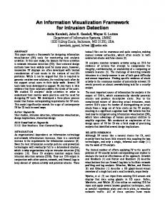
3.2 RFID-Related Activity Timeline In order to demonstrate the relationship between the activity timeline during the life cycle and the related RFIDbased processes that should be performed based on the proposed framework, a typical work pattern is adapted from Yoon et al. (2006). In this pattern, the components follow the following steps in the life cycle of the constructed facility: design, ordering, manufacturing, shipping, transportation, receiving, stockyarding, lifting up, piling up, installation, inspection and quality control, and maintenance. The design and maintenance phases are added to the construction work pattern to extend the applicability of the proposed approach to the lifecycle of the facility. Different players, activities and component status in the database during the lifecycle are shown in FIG. 1. The activities are described following the phase number in FIG. 1. (1) Design phase: A unique ID is automatically assigned to each component. This ID could be based on the ID of the component in a building information model, such as the Industry Foundation Classes (IFC) (IAI 2002). The assigned ID is defined in the 3D model and a record for the component is created in the database. (2) Ordering phase: The ID of a component is communicated in the ordering phase to the manufacturer. By sending the order, the status of the component in the database is set to ordered. (3) Manufacturing phase: The manufacturer produces the ordered component, creates the ID on the appropriate tag based on the order document, and attaches the tag to the component. The tag is scanned in the manufacturing site and the data is communicated to the project office. The status of the component in the database changes to manufactured. (4) Shipping phase: The component is scanned before being shipped and its status in the database is changed to shipped based on the information from the carrier. (5) Receiving phase: When a component is received in the site, it is inspected and scanned, and the status of the component in the database is changed to received. After this phase, based on the type of the component, it will be stored, lifted up or directly installed. (6-9) Stockyarding, lifting up, piling up and installation phases: In all these phases the component is scanned and the status information is automatically changed in the database. By finishing the installation, the finish date for the task associated with the component in the scheduling software would be updated. The exact information about the finish date of the task would improve the data accuracy of progress measurement. (10) Inspection and quality control phases: The inspection and quality control will be done after installation, the component is scanned during the inspection and the status of the database is changed to QC passed. (11) Maintenance phases: The components that need to be maintained and inspected regularly (e.g., HVAC system and other mechanical parts) are scanned by the maintenance team and the status in the database is changed to inspected. During the maintenance phases the status of the components that are waiting to be inspected is changed to waiting for inspection. Using the FM software, the status of the components that needs to be inspected is changed in the database.
7th International Conference on Construction Applications of Virtual Reality: October 22-23, 2007
227
FIG. 1: RFID-Related Activity Timeline
3.3 Implementation Challenges and Cost-Benefit Analysis Relatively high cost of implementation, deployment risks and technology risks should be taken into account is the system detailed design. Hence, a thorough feasibility study is required to select the target components to be tagged based on the business plan and cost-benefit analysis. Several technological and implementation challenges exist: (1) Organizational challenges: RFID applications in the construction industry are relatively new and have not been deployed on a large scale. It is expected that there will be resistance to changes in the process re-engineering. In addition, resistance to information sharing and privacy issues are expected; (2) Standardization challenges: RFID technology is developing fast and is still evolving with new standards and protocols. Creating RFID systems that are compatible with the multitude of industries and usages should be studied carefully; (3) Readability and data accuracy problems: These problems are related to the physical properties of the components to be tagged, the antenna design, and other environmental factors, such as RF noise. In a crowded construction site, where metallic objects are abundant, there are problems with false or missing reads as a result of radio waves being easily blocked, distorted, absorbed, or interfered with; (4) System-level challenges: such as determining the number, type and placement of tags. The number of the tags that should be attached to each component guaranteeing the readability varies depending on the shape and size of the components and also the installation location; (5) The nominal service life of RFID tags is about 10 years. However, most components in a facility will remain in service more that 10 years. In addition, active tags have batteries that should be replaced every 3-5 years. Due to the large scale implementations of the RFID systems in different sectors and the huge market demand and with the help of new technologies, the unit price of RFID hardware is decreasing. However, there are several other direct and indirect costs associated with the system design, implementation, training, maintenance and operation. The maximum use of the gathered data by different systems and project players throughout the life cycle of the facility would justify the costs associated with the system and these costs can be shared amongst these players. Developing business models for cost sharing is one of the challenges of this research. The benefits of an RFID deployment can be categorized based on time (short-term vs. long-term) and tangibility (direct vs. indirect) (Moradpour 2005). As discussed in Section 1, there are several benefits associated with the implementation of the proposed approach. The provided data will assist different processes ranging from construction progress monitoring to inspection activity visualization. The main benefit results from the availability of accurate data, which have been collected using the RFID technology and are stored in a central database so that they are shared among different players (i.e., owner, contractors, managers, field workers, etc.) throughout the lifecycle of the facility in a collaborative environment. It is expected that having the detailed information about the components of a facility would improve the quality of the construction project and FM procedures.
4. PROTOTYPE SYSTEM STRUCTURE AND CASE STUDY The prototype system is composed of six subsystems: (1) the database that store the data extracted from the Building Information Model (BIM), which will be updated by RFID reads and also other software updates (e.g., inspection data); (2) the 3D modeling software; (3) the scheduling software; (4) the 4D simulation software; (5) the FM software; and (6) the RFID reader interfaces. The communications between the subsystems are based on standard protocols providing scalability and interoperability. The software components and the connectivity method between
7th International Conference on Construction Applications of Virtual Reality: October 22-23, 2007
228
each other are shown in FIG. 2. Any database supporting Open Database Connectivity (ODBC) can host the information. The structure proposed for the database should include 18 fields which are: ID, IFC No., Status, Type, Ordering date, Manufacturing date, Shipping date, Receiving date, Stockyarding date, Piling-up date, Lifting-up date, Assembling date, Installation date, QC control date, Task start, Task finish, Last inspection date and Next inspection date. The 4D simulation software obtains the geometrical information from the 3D software and the timing and status information from the database to produce different real-time views of the facility using a predefined coloring scheme. These views help project planners and the FM team to better visualize the status of the facility. In our case study, we focused on the progress monitoring and lifecycle management of the HVAC components in the new building of John Molson School of Business (JMSB) of Concordia University. The construction project is a high-rise building located in downtown Montreal. VicoSoftware suite is used for 4D modeling and scheduling (Vico Software 2007). The main software in the suit, Constructor, is a complete package for building construction models and linking them with scheduling applications. The other used software packages are Control for scheduling and 5D Presenter for progress simulation. Microsoft Project is also used for schedule management and progress monitoring. The RFID reader application module is being developed for entering data into the database. Intermec EPC global Gen2 passive RFID tags are used. The tags are operating in UHF frequency and are compatible with EPC and ISO compatible readers. The tags have a robust physical package and are designed for exposure to harsh environments. High gain passive tags are relatively cheap and can be detected by mobile readers in their readability range and are functional during the lifecycle of the components. FIG. 3 shows the 4D simulation of the JMSB project, the anticipated task durations are based on the initial planned schedule and the actual durations for finished tasks are updated using the database. FIG. 4 shows sample snapshots of 4D visualization of the HVAC system on the 14th floor of the building. FIG. 4(a) shows the status of the components during the construction phase. The components that are installed are shown in black and the components that are lifted up but not yet installed are shown in red, the components that are in the stockyard and have not been lifted up are shown in grey (bright colour). FIG. 4(b) shows the status visualization during the maintenance phase. The component in green is waiting for inspection and the component in dark brown needs to be repaired based on the database status. The exact number and types of the needed tags and the precise location of attaching the tags in our case study is being designed and tested for different components. The system is at an early phase of implementation. It is hoped that more implementation details and field testing results will be presented at the conference and in further publications
FIG. 2: Proposed System Structure
FIG. 3: 4D Simulation of the JMSB Project
7th International Conference on Construction Applications of Virtual Reality: October 22-23, 2007
229
(a) Construction Phase
(b) Maintenance Phase
FIG. 4: HVAC 3D Drawing of one Floor of the JMSB Building
5. CONCLUSIONS AND FUTURE WORK The paper proposed a framework for lifecycle status tracking and visualization of constructed facility components. This framework aims to extend the previous research about using RFID in the construction phase or the maintenance phase of a facility while considering the organizational, procedural, technical, and cost-benefit issues of implementing a system based on the framework. The tags remain within the facility during its lifecycle and are used for inspection and maintenance purposes after the construction and also for supply chain management. The visualization issues were discussed including color coding and using the 3D model to facilitate the management of the tags. The major contribution of this paper is describing the required activities for tracking facility components at different phases of the life cycle. A case study was shown to demonstrate the visualization options for an HVAC system at the construction and maintenance phases. While the paper discussed the concept of the framework, several issues have to be studied in detail to establish the guidelines for designing a system based on this framework. Because of the relatively high cost of implementation, a major decision is to find the balance between the target components to be tagged and the number and type of the RFID tags. Our future work will focus on grouping the components according to their physical and logical relationships (some of these relationships are described in the building information model) and finding the number and types of the RFID tags which should be attached to these components in order to optimize the ROI of the project.
6. ACKNOLEDGMENET The authors would like to acknowledge the contributions of Mr. Basim El-Hamwi for developing the 3D model of JMSB building and Mr. Ayham Krayem for adding the HVAC system to the 3D model. The software has been provided by VicoSoftware. The data of the case study have been provided by Mr. Gilles Desrochers from Genivar. The cooperation of Mr. Peter Bolla and Mr. Rick Young from the FM office at Concordia University is appreciated.
7. REFERENCES Chang H., Kang S., and Hsieh, S. (2007). Color schemes in 4D construction management tools, Proceeding of ASCE Workshop on Computing in Civil Engineering, Soibelman L. and Akinci B. (editors), Pittsburgh, PA. Chin S., Yoon S. W., Kim Y. S., Ryu J., Choi C. and Cho C. Y. (2005). Realtime 4D CAD + RFID for Project Progress Management, Proceedings of Construction Research Congress, San Diego, California, USA. Construction Industry Institute (CII) (1987). Project Control for Construction, Publication No. 6-5.
7th International Conference on Construction Applications of Virtual Reality: October 22-23, 2007
230
Construction Industry Institute (CII) (1986). Project Control for Engineering, Publication 6-1, The Construction Industry Institute, The University of Texas at Austin, Austin, Texas. Ergen E., Akinci B., East B., and Kirby J. (2007). Tracking components and maintenance history within a facility utilizing radio frequency identification technology, Journal of Computing in Civil Engineering, Vol. 21, No. 1, 11-20. Fischer M., and Kam C. (2002). PM4D final report, Technical Rep. No. 143, Centre for Integrated Facility Engineering, Stanford Univ., Stanford, California. Fleming Q.W. and Koppleman J. M. (1996). Earned value project management. Project Management Institute (PMI), Upper Darby, PA, USA. Ghanem A.G. and AbdelRazig Y. A. (2006). A framework for real-time construction project progress tracking, Earth and Space 2006, (188) 112. Goodrum P., Mclaren M., and Durfee A. (2005). The application of active radio frequency identification technology for tool tracking on construction job sites, Journal of Automation in Construction, Volume 15, Issue 3, 292302 Griffis F. H., Carrie S. Sturts (2001). 3D CAD and FIAPP: Three-dimensional computer models and the fully integrated and automated project process. Research summary 152-1, Construction Industry Institute (CII). Hammad A., Zhang C., Hu Y., and Mozaffari E. (2006). Mobile model-based bridge lifecycle management systems, Journal of Computer-Aided Civil and Infrastructure Engineering, Volume 21, Issue 7, 530-547. Hu W., He X. and Kang J. H. (2005). From 3D to 4D visualization in building construction. Computing in Civil Engineering 2005 International Conference; July 12-15, 2005, Cancun, Mexico. International Alliance for Interoperability (IAI), Modeling Support Group (2002).IFC 2x Model Implementation Guide. < http://www.iai-international.org/Model/IFC(ifcXML)Specs.html> Jaselskis E. J., Anderson M. R., Jahren C. T., Rodriguez Y., and Njos S. (1995). Radio-frequency identification applications in construction industry. Journal of Construction Engineering and Management, 121(2), 189– 196. Jaselskis E. J., EI-Misalami T. (2003). Implementing Radio Frequency Identification in the Construction Process, Journal of Construction Engineering and Management, ASCE, 129(6). Kamat V. R., and Martinez J. C. (2001). Visualizing Simulated Construction Operations in 3D. Journal of Computing in Civil Engineering, 15(4), 329-337. Kang J. H., Anderson S. D., and Clayton M. J. (2007). Empirical study on the merit of web-based 4D visualization in collaborative construction planning and scheduling. Journal of Construction Engineering and Management, 133(6), June 2007, 447-461 Kiziltas S., and Akinci B. (2005). The need for prompt schedule update by utilizing reality capture technologies: A case study. Proceedings of the Construction Research Congress. April 5-7, 2005, San Diego, California. Moradpour S. (2005). Solving the RFID cost-benefit equation. RFID Product News, 2(1). Rischmoller L., Fisher M., Fox R., and Alarcon L. (2001). 4D planning and scheduling (4D-PS): Grounding Construction IT Research in Industry Practice. Construction Information Technology, Proc., CIB W78 Int. Conf. IT in Construction in Africa, Mpumalanga, South Africa. SAP (2005). “SAP Mobile asset management at Fraport AG.” . Simons K. L., Thornberry H. L., and Wickard D. A. (1988). Simulation system for construction planning and scheduling. Proc., Joint ASME/IEEE Power Generation Conf., Philadelphia.
7th International Conference on Construction Applications of Virtual Reality: October 22-23, 2007
231
Song J. (2005). Tracking the location of materials on construction projects. Submitted in Partial Fulfilment of the Requirements for the Degree of Doctor of Philosophy, Faculty of the Graduate School of the University of Texas at Austin. Thomas H. R., and Mathews C. T. (1996). An analysis of the methods for measuring construction productivity. CII Source Document 13. Vico Software (2007). Website: Yabuki N., Yamashita T., Shimada Y. and Sakata T. (2004). Application of RFID tags to an on-site inspection support system for large dams, Proc. of the third Civil Engineering Conference in the Asian Region, Seoul, Korea, 397-400. Yabuki, N., and Oyama, T. (2007). Application of Radio Frequency Identification Technology for Management of Light Weight Temporary Facility Members, ASCE Workshop on Computing in Civil Engineering, Pittsburgh, 697-704. Yoon S. W., Chin S., Kim Y. S., and Kwon S. W. (2006). An application model of RFID technology on progress measurement and management of construction works. ISARC2006, 779-783. Williams M. (1996). Graphical simulation for project planning: 4D planner, Proc., Computing in Civil Engineering, Vanegas J. and Chinowsky P. (editors.), ASCE, Reston, VA, 404-409.
7th International Conference on Construction Applications of Virtual Reality: October 22-23, 2007
232