2015 International Seminar on Intelligent Technology and Its Applications
Combining Simplified Firefly and Modified P&O Algorithm for Maximum Power Point Tracking of Photovoltaic System Under Partial Shading Condition Yanuar Mahfudz Safarudin, Ardyono Priyadi
Mauridhi Hery Purnomo, Margo Pujiantara
Instrumentation, Measurement, and Power Systems Identification Laboratory Institut Teknologi Sepuluh Nopember Surabaya, Indonesia
[email protected],
[email protected] Abstract— This paper proposes the combination of firefly and P&O algorithm to get both of its benefit. Simplified firefly algorithm used for escaping partial shading multi peaks condition due to Partial Shading Condition (PSC). When it goes yet to converge, the algorithm used is switched to faster modified P&O algorithm. This proposed algorithm is to obtain the optimal solution for Maximum Power-Point Tracking (MPPT) of Photovoltaic (PV) system under three shaded conditions. The simulation results are compared with traditional Perturbation and Observation (P&O) and Simplified Firefly Algorithm (SFA) to verify the proposed method performance. The main advantage of proposed algorithm is faster convergence and tracking speed compared to its previous method that is Simplified Firefly Algorithm (SFA). Keywords— SFA; P&O; MPPT; PSC; PV systems. I.
INTRODUCTION
In the current situation, solar energy becomes a key issue for renewable energy resource and clean energy since convensional energy crysis happen and climate changing become real due to green house effects. The developing solar energy is one of chance to avoid this circumstance situation. One kind of method is to convert solar energy into electric energy using PV system that have advantage such as low maintenance cost, no emission, and free source of abundant solar energy. However it requires high initial cost in this date. Additional, PV system currently must be controlled to produce the electricity at maximum rate. The MPPT is a common method to track maximum power of PV system and may convert in any temperature and/or solar isolation condition. One kind of control techniques required MPPT to track PV output power is DC-DC converter and/or. The other problem is occurred when an obstacle object block up solar insolation to some part of PV surfaces. This condition is named PSC. The effect of PSC on PV system may reduce the electricity production and has been investigated by
Electrical Engineering Department Institut Teknologi Sepuluh Nopember Surabaya, Indonesia
[email protected],
[email protected] some researchers. However it varies depend on configuration of PCS and bypass diode [1]-[2]. PV system under PSC becomes more complexity since multiple peaks are exist. Some researchers have published the MPPT methods such as modified P&O [3], PSO [4], firefly algorithm [5], and its combinations [6][8] for solving partial shading problems. From the newest reference, its known that Simplified FA with beta update is currently best method for optimizing MPPT of PV system under partial shaded condition. Simplified FA with beta update has simpler, faster, and more accurate algorithm than standard FA. But in [8], in some case P&O algorithm has the advantage in tracking speed than simplified FA, although the power that P&O tracked far from maximum power. [8] This paper proposes new combination of SFA and modified P&O to MPPT of PV system under PSC. This proposed algorithm is to obtain the optimal solution for MPPT of PV system under three shaded conditions. The simulation results are compared with traditional P&O and Simplified Firefly Algorithm (SFA) to verify the proposed method performance. II.
PHOTOVOLTAIC UNDER PARTIAL SHADED CONDITION MODELLING
The PV model and partial shaded condition used in this paper is described as the following sentences. A. PV Model
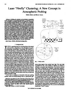
Fig. 1. PV Modeling
Figure 1 shows the PV model used in this paper and output current (I0) as stated in [4] is given by:
978-1-4799-7711-6/15/$31.00 © 2015 IEEE
(1)
181
Where Ipv represents short circuit currentt affected by solar insolation and surface temperature and cann be calculated as below: (2) 2
Where S is solar insolation in W/m , and Sref is reference of solar insolation. T is PV survace temperature in Kelvin, and Tref is reference of PV surface temperature. Isco iss PV module short circuit current in standart insolation and tempperature written in PV specification. Id is diode current and can be expressed ass follows: (3) Where Isat is diode saturation current, and Vt is thermal voltage and can be determined as below: (4) Where η is PV ideality factor, k is Boltzm mann’s constant in joule per kelvin, Ns is number of seriess cells, and q is electronic charge in coulombs. The pow wer generated by photovoltaic (Ppv) can be expressed as follow ws: (5) B. PV System and PSC In this paper, four PVs are connected in seeries condition and every single PV are connected into bypass dioode. The simulation model is used the three schemes s of PSC to test the performance of proposed methods. The T differences of each schemes are the number of multiple peeaks that represent level of complicated optimization. Optim mization problem become more complicated if there are more peaks occurred in the same time and situation. There is only one string of series PV syystem used in this paper since multiple peaks problem dependss on configuration of bypass diodes that connected in series andd has stated in [1]. Figures 2-3 are illustrated tree scheme of PSC and its P-V curve under PSC used in this paper, respectivvely.
Fig. 3. P-V curve of partiaal shading condition scheme
The shading scheme can bee explained as follows: shading scheme 1 has two peaks, and the global maximum power is s 2 has two peaks, and the 123.198 W. And then shading scheme global maximum power is 188.88 W. Finally shading scheme 3 g maximum power is 155.2 has four power peaks, and the global W. The proposed algorithm should s detect global maximum power, and not be trapped into local l maximum power. The DCDC converter used in this papper is buck type converter with resistive load. The objective function is not to maximize power that generated by photovoltaic repreesented in equation (5) only. But, it is also duty cycle of DC--DC converter become control variable of optimization probblem. Duty cycle may change voltage and current that geneerated by photovoltaic, wich is mean change the power generatted by photovoltaic. III.
PROPOSSED ALGORITHM
From [8], it’s known that in i some case P&O algorithm is quite fast than Simplified Firefly Algorithm. But P&O algorithm often trapped in local power peaks and has high power ripple when it goes steeady state. This paper proposes combination between Simplifieed FA with beta update [8] and modified P&O [3]. Simplified Firefly Algorithm will make it escapes from local peaks andd detect highest global power peaks. When global power peaaks range detected, the searching algorithm is switched to modiffied P&O, so the searching time became faster. To reduce the power p peaks ripple when it goes in steady state condition, a litttle modification will be add in P&O algorithm [3]. Fig. 2. Three scheme of partial shading coondition
182
A. Simplified Firefly Algorithm (SFA) Simplified FA algorithm became simplifiied by neglecting α and γ parameter because MMPT problem was very simple (only has one control variable such as dutyy cycle). Standard firefly equation can be calculated using follow wing equation [7]: (6) By neglecting α and γ parameter, the simplified firefly equation became following equation [8]: (7) Xi and Xj represent less bright firefly i annd brighter firefly j position. β is firefly attractiveness factorr, and γ is light absorption coefficient. And then α represent r random coefficient, and represent random vector. v In MPPT application, the objective function is photovooltaic output power and firefly position represent duty cycle. And yet, to make it faster computation, β coefficient will be updated each iteration. β coefficient represent firefly attractiveness factor. Higher β coefficient wiill guarantee faster computation, but less accurate. And then, low w β coefficient will make the computation slow, but more accuurate. β coefficient will be low at first, but it goes higher in the next iteration. It means that each next iteration firefly will moove faster than the last iteration. This modification will maake the proposed algorithm faster than standard firefly, but stilll accurate [8]. B. Modified Perturb and Observation mple algorithm that P&O algorithm is a traditional and simp widely used in early time of MPPT appplication. A little modification used in this paper, that is the movement m step will be reduced each time it’s moving to oppossite direction. The purpose of modification is to reduce pow wer ripple when it reaching steady state condition. P&O modificcation algorithm is shown on figure 4.
Fig. 4. Modified P&O algorrithm with updated coefficient
P represents power generatted by photovoltaic, and then D represents duty cycle. X is a value v ranging from 0 to 1. From figure 4, it can be seen that the value of c will be multiplied by x value that ranging from 0 too 1. It means that the value of c will be reduced each time duty d cycle moving to opposite direction. With this modificatioon, power ripple will be reduced, compared to traditional P&O. C. Combination This paper proposes combination between Simplified FA and modified P&O to get the right duty cycle, so maximum power will be generated by phootovoltaic. The function of SFA is to escape from multiple pow wer peaks due to partial shading condition. And then modified P&O P will continue the proposed algorithm to search optimal dutty cycle.
Fig. 5. Simulation result of shading scheme 1
183
Fig. 6. Simulation result of shading scheme 2
IV.
SIMULATION RESULTS AND DISCUSSION
Figures 5-7 show solving shading schem me 1-3 respectively to verify the performance of proposed methood. The simulation has done using MATLAB Simulink softwarre. The traditional P&O and Simplified FA are also described for comparison as i V, current in A, simulated at [8]. The power in W, voltage in and duty cycle are used for performance measurement. P is chosen as The constant parameter of traditional P&O 0.01. And then the Simplified firefly parameeter of β is chosen as 0.3, and will be increased by 0.25 each iterration until it reach 0.9. It’s been described at [8] that P&O algoorithm trapped into local maximum power at shading schemee 2 and 3. P&O tracking speed very much based on constant parameter. Higher
constant parameter means fasteer but less accurate of searching. And then there is much ripple when output power reaches steady state level. A algorithm with β update was From [8], the simplified FA quite fast and accurate to deteect maximum power point that generated by photovoltaic. Thiss algorithm was also never been trapped into local power peaks due to partial shading condition. w properly, and may track The proposed method has worked global maximum power at all a shading scheme. The main advantage of proposed algorithhm is tracking speed that slightly increased compared to previouus SFA algorithm. The proposed algorithm was also never beenn trapped into local power peaks due to partial shading conditionn.
Fig. 7. Simulation result of shading scheme 3
184
TABLE I. COMPARISON OF THREE METHOD
Shading Scheme
Maximum Power (Watt)
1
123.198
2
188.88
3
155.2
Parameters Power Tracked (Watt) Tracking Speed (s) Tracking Efficiency (%) Steady State Ripple Power Tracked (Watt) Tracking Speed (s) Tracking Efficiency (%) Steady State Ripple Power Tracked (Watt) Tracking Speed (s) Tracking Efficiency (%) Steady State Ripple
Table I shows that the main advantages of proposed method is faster than P&O and previous SFA algorithm. The proposed method is also never trapped into local optimum and produce efficiency always above 95%. However, the tracking efficiency of SFA is somewhat better than proposed algorithm in shading scheme 1 and 2.
P&O 73.258 0.434 59.46362766 Poor 151.097 0.604 79.99629394 Poor 151.037 0.607 97.31765464 Poor
Tracking Method SFA 123.009 2.205 99.84658842 Good 187.335 2.512 99.18202033 Good 149.623 2.603 96.40657216 Good
Proposed Algorithm 122.799 1.776 99.67613111 Good 186.884 1.744 98.94324439 Good 154.775 1.783 99.72615979 Good
Table II and III shows the performance of P&O, SFA, and proposed algorithm in case of irradiance and temperature variation. The shading scheme that used in this simulation is shading scheme 3.
TABLE II. COMPARISON IN CASE OF AVERAGE IRRADIANCE VARIATION
Average Irradiance
Maximum Power (Watt)
1000
155.2
900
139.793
700
108.765
Parameters Power Tracked (Watt) Tracking Speed (s) Tracking Efficiency (%) Steady State Ripple Power Tracked (Watt) Tracking Speed (s) Tracking Efficiency (%) Steady State Ripple Power Tracked (Watt) Tracking Speed (s) Tracking Efficiency (%) Steady State Ripple
P&O 151.037 0.607 97.31765464 Poor 133.523 0.576 95.51479688 Poor 103.455 0.516 95.11791477 Poor
Tracking Method SFA 149.623 2.603 96.40657216 Good 136.174 2.791 97.41117223 Good 100.646 2.205 92.53528249 Good
Proposed Algorithm 154.775 1.783 99.72615979 Good 138.786 1.83 99.2796492 Good 100.449 1.871 92.35415805 Good
TABLE III. COMPARISON IN CASE OF SURVACE TEMPERATURE VARIATION
Survace Temperature
Maximum Power (Watt)
25
155.2
30
152.712
35
150.226
Parameters Power Tracked (Watt) Tracking Speed (s) Tracking Efficiency (%) Steady State Ripple Power Tracked (Watt) Tracking Speed (s) Tracking Efficiency (%) Steady State Ripple Power Tracked (Watt) Tracking Speed (s) Tracking Efficiency (%) Steady State Ripple
P&O 151.037 0.607 97.31765464 Poor 148.585 0.604 97.29752737 Poor 145.39 0.608 96.78085019 Poor
Tracking Method SFA 149.623 2.603 96.40657216 Good 149.472 2.726 97.87835926 Good 149.296 2.674 99.38093273 Good
Proposed Algorithm 154.775 1.783 99.72615979 Good 152.297 1.793 99.72824663 Good 149.816 1.824 99.72707787 Good
185
V.
CONCLUSSIONS
Combination between Simplified Firefly Algorithm with beta update and modified P&O has been proposed. The function of SFA is to escape from multiple power peaks due to partial shading condition. And then modified P&O will continue the proposed algorithm to search optimal duty cycle. The main advantage of proposed algorithm is faster convergence and tracking speed. It means that Combining SFA and P&O algorithm may also solve the MPPT optimization problems. However, the parameters of proposed algorithm need to be investigated, so it’s tracking efficiency will be better than SFA algorithm. This paper only deals with software simulation to test the performance of proposed algorithm. Hardware implementation and comparison with other algorithm will be investigated in the next paper. ACKNOWLEDGMENT First author would to thanks to Indonesian Directorate General of Higher Education for giving the full financial support to study in Master program at ITS, Surabaya. And also thank you for my parents and my teacher. REFERENCES [1]
[2]
[3]
[4]
[5]
[6]
[7] [8]
186
A. Dolara, G.C Lazaroiu, S. Leva, “Experimental Investigation of Partial Shading Scenarios on PV (Photovoltaic) Modules”, ScienceDirect, Energy 55 (2013), p466-475. Y. J. Wang and P. C. Hsu, “Analytical modelling of partial shading and different orientation of photovoltaic modules”, IET Renew. Power Gener., vol. 4, no. 3, pp. 272-282, May 2010. H.Renaudineau, A. Houari, J.-P. Martin, S. Pierfederici, F. M. Tabar, “A New Approach in Tracking Maximum Power Under partially Shaded Condition with Consideration of Converter Losses”, ScienceDirect, Solar Energy 85 (2011), p2580-2588. K. Ishaque, Z. Salam, “A Deterministic Particle Swarm Optimization Maximum Power Point Tracker for Photovoltaic System Under Partial Shading Condition”, IEEE Trans. Industrial Electronics, vol. 60, no. 8, pp. 3195-3206, August. 2013. K. Sundareswaran, S. Peddapati, S. Palani, “MPPT of PV Systems Under Partial Shaded Conditions Through a Colony of Flashing Fireflies”, IEEE Trans. Energy Conversion (2014), early acces K.L. Lian, J.H. Jhang, I.S. Tian,“ A Maximum Power Point tracking Method Based on Perturb-and-Observe Combined with Particle Swarm Optimization”, IEEE Journal of Photovoltaics, vol. 4, no. 2, pp. 626-633, March. 2014. X.-S. Yang, Nature-Inspired Metaheuristic Algorithm, Beckington, U.K.: Luniver Press, 2008. Y.M. Safarudin, A. Priyadi, M.H. Purnomo, M. Pujiantara,“ Maximum Power Point Tracking Algorithm for Photovoltaic System Under Partial Shaded Condition by Means Updating β Firefly Technique”, 6th International Conference on Information Technology and Electrical Engineering (ICITEE), October. 2014.
APPENDIX PARAMETER OF SINGLE PHOTOVOLTAIC MODULE
Parameter Maximum power (Pmax) Open Circuit Voltage (VOC) Maximum Power Voltage (VMP) Short Circuit Current (ISCO) Maximum Power Current (IMP)
Value 60.46 W 21.98 V 21.12 V 2.95 A 2.863 A
PARAMETER OF BUCK CONVERTER
Parameter Capacitor, C Inductor, L Internal resistance of Inductor, RL Switching frequency, f
Value 470 µF 2.7 mH 0.2 Ω 20 kHz