Combining Use Cases and Operational Profiles in UML Greg Butler, Adrian Cretu, Ferhat Khendek Computer Science, and Electrical and Computer Eng. Concordia University Montr´eal H3G 1M8 Canada
[email protected]
Abstract Use cases are the accepted way of modeling the functional requirements of a system within the object-oriented community. A quantitative view of system requirements is provided by operational profiles. They are familiar tools in telecommunication systems, but are not so familiar in the object-oriented community. A reconciliation of use cases and operational profiles is presented as a means for requirements engineering, prioritizing development and testing, and allowing statistical use testing and reliability estimation. We show how to present the combined model of use cases and profiles using the Unified Modeling Language.
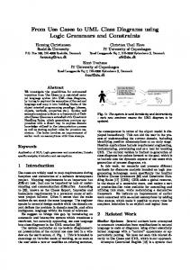
1. Introduction Use cases capture the functionality of a system. They have been shown to improve requirements gathering because they are accessible to users. Use cases have also been used as the basis of project management, and for traceability across development and test phases. Operational profiles capture quantitative usage information of a system. They allow statistical use testing and reliability estimation, as well as prioritization of tasks during the software process. A reconciliation of uses cases and operational profiles is presented as a means for requirements engineering, prioritizing development and testing, and allowing statistical use testing and reliability estimation. The reconciliation shows how the use case model for a system can include an operational profile, thus capturing both functional specification and a quantitative usage specification. We will use an example to illustrate the concepts from use cases and from operational profiles, how we reconcile them, and how we propose to model them un UML. Figure 1 gives the overall context of our mobile telephony example showing the Home Location Register(HLR), which
is a database of subscriber information, and the Visitor Location Register(VLR), which is the local database of information on subscribers roaming in the service area of the Switch. It should be kept in mind that all our probabilities given in profiles are purely fictitious.
SWITCH BASE STATION
VLR
MOBILE STATION
SWITCH
VLR HLR
Figure 1. Context for Mobile Telephony Example
We present the background material on use cases and operational profiles together with the description of a simple formal model of event sequences that underlies both use cases and operational profiles. Section 4 presents a combined view of the concepts from both use cases and operational profiles. In the conclusion we highlight the benefits of the combined approach. There are many definitions of use cases and its associated terminology. Most of our work was settling on the appropriate set of definitions in order to make the reconciliation with operational profiles comprehensive. In contrast, the terminology for operational profiles is well-defined in the literature.
2. Use Cases This section provides background on use cases and definitions of the terminology. It is divided into a discussion of context in terms of the host system, definitions of use cases
and scenarios, then a presentation of the many ways to describe scenarios, and a discussion of methodology. There are many viewpoints of use cases in the literature. Our viewpoint is drawn mainly from Cockburn [1] and Regnell [2].
are the actors involved in each use case. This is still a blackbox view of the target system. Mobile Telephony System
2.1. Host System Environment Subscriber
Use cases capture the functionality of a system, called the target system, as it is meant to behave in a given environment called the host system. A use case describes how a group of external entities, called actors, make use of the system under consideration. The use they make is modeled by the passing of signals or information between the actors and the system. We will call these messages. Sometimes it is useful to distinguish between stimuli, which are messages from actors to the system, and responses, which are messages from the system to actors. Figure 2 illustrates one view of the host system, where the target system is just one of the actors. All actors interact, as shown by the arrows, but use cases model only the interactions with the target system (the solid arrows). Many descriptions of the target system’s requirements do not model the other interactions, although they are important [3].
make call
check account
call back
Switching System
Figure 3. Use Case View of the Target System
The modeling of a use case is done in several ways: for example, by name, or by a textual synopsis. One high-level approach is as a collection of scenarios. Potts [5] defines a scenario as “a description of one or more end-to-end transactions involving the required system and its environment”. A use case encompasses a collection of scenarios, since there may be several ways in which an actor can (successfully or unsuccessfully) attempt a task. The main scenario describes the usual way in which the task is successfully performed. Typically, in the main scenario, the simplest sequence of interactions is described, and it is assumed that all steps execute successfully. A variant scenario describes another way of using the system where it is assumed that all steps execute successfully. An exceptional scenario describes a scenario where exceptional or error conditions may arise. It may be possible to recover from the exceptions and therefore successfully complete the task — this is called a recovery scenario — or it may not be possible to recover — this is called a failure scenario. An alternative scenario is either a variant or exceptional scenario. Typically, a scenario is given as simple narrative text, which can be complemented by a script; by an Agent-Action table [5]; or by an interaction diagram for increased precision. A scenario groups together end-to-end dialogues based upon the task or transaction they describe. A scenario is a set of end-to-end dialogues to which the system responds by executing a similar sequence of actions. An action is a unit of activity within the system in response to a message. Scenarios group the dialogues according to some criteria. This is a horizontal grouping of dialogues. It is also possible to divide a scenario vertically into a sequence of episodes. Each episode represents a subtask, or the parts
Host System
Actor
Operator Callee
Actor Actor
Target System
Figure 2. Host System View of the Target System
2.2. Use Cases and Scenarios Several actors may participate in a use case. The primary actor is the actor who initiates the use case, while the other actors are called secondary. A use case is a description of a cohesive set of dialogues that the primary actor initiates with a system. The dialogues are cohesive in the sense that they are related to the same task, or form part of the same transaction. Cohesiveness is often determined by having a goal in common for the tasks, or by having a common responsibility that must be fulfilled [1, 4]. Figure 3 shows the expanded view of the target system, where individual use cases are indicated, as 2
of the dialogues in the scenario that perform the subtask. Hence, an analysis use case may model a group of scenarios or a group of episodes [5, Figure 3,page 26]. Figure 4 shows a scenario broken into three episodes: Failure to Connect, Operator Intervention, and Successful Call. Highlevel Message Sequence Charts (MSCs) [6, 2], also show a roadmap of episodes, each of which may be described by a basic MSC.
A white-box use case not only models the external interactions of the system, but also represents the internal structure of the system and the internal actions of the system. The internal structure is usually a high-level decomposition into subsystems. For example, a mobile telephony system might model the Mobile Station, Base Station, and Network of Switches as subsystems. The internal actions are often modelled using interaction diagrams or using message sequence charts (MSC) [6]. This modeling of internal details is a step in verifying that the use case requirements can indeed be implemented in terms of the proposed subsystems.
Episode 1: Failure to Connect 1.1 Subscriber dials Callee (old number) Episode 2: Operator Intervention 2.1 Operator informs Subscriber of new number
3. Operational Profiles This section presents background on operational profiles and definitions of the terminology as used in [10]. A usage specification is a quantitative description of how users employ a system. There is a distinction made between usage as described at the requirements stage, and at the operational stage. For the former, the actual system has not been designed yet, so the usage is described in terms of functions. For the latter, the usage is described in terms of operations. To determine the reliability of a completed system in a valid statistical way, one wants to test the system with tests that reflect the actual pattern of usage in the real world, so that any conclusions drawn from the test results can be claimed as indicative of the behaviour of the delivered system. For this, one needs a model of the actual distribution of usage: that is, how frequently is each system operation called relative to the others, and what is the distribution of argument values across operation calls. So for our example, we might determine that dial digit is performed 36% of the time, lift receiver 3%, speak 58.5%, and disconnect 2.5% of the time. This is precisely an operational profile, however, other components also make up the usage specification since they are needed in the process of developing an operational profile. A profile captures the frequency of occurrence of a set of disjoint elements. It is a probability distribution. Each profile is typically presented as a table, with the combined profiles presented as a tree, as in Figure 10, to emphasise that context is important, and that each profile is given within its own context. A run is a unit of work for the system that is the smallest division of work that can be initiated externally. Runs are grouped into run types if they share the same input state for the system. A function is a set of run types for the system as conceived during requirements, while an operation is a set of run types for the system as built. A functional profile is a quantitative description of (functional) requirements needed to satisfy the needs of the user.
Episode 3: Successful Call 3.1 Subscriber dials Callee (new number) 3.2 System connects Subscriber and Callee 3.3 Subscriber talks to Callee 3.4 Subscriber disconnects Figure 4. A Recovery Scenario as Episodes
2.3. Methodology Use cases, together with the range of notations for describing scenarios, support a methodology for requirements engineering [4, 2, 7]. Scenarios themselves are very popular within the field of requirements engineering [5, 8] and design [9]. The methodologies identify the system operations, and can transition from system requirements to subsystem specification once a system architecture is chosen. A requirements use case is a use case that describes a complete user task or activity. For a requirements use case, the system performs a meaningful unit of work of value to the primary actor. An analysis use case describes a service, feature, or function that is offered by the system and is initiated by an actor. An actor may perform a requirements use case by initiating a sequence of analysis use cases. A requirements use case is a special kind of analysis use case where the service being described is a complete user task rather than simply a subtask. An episode can give rise to an analysis use case. These can be further refined until one is at the level of atomic use cases, which represents a primitive unit of interaction with the system. A black-box use case treats the system as a black-box and models the use case in terms of interactions, and does not describe the system’s (internal) actions. Hence, the system is just another actor that sends and receives messages. 3
A functional profile is developed because the users have the knowledge about the tasks the system should perform, including the knowledge of the distribution of those tasks. However, users think of tasks in terms of requirement functions, not system operations. Hence, the elaboration of requirements and usage must first be at the functional level. For our example, we might decide the only functions are make call, check account, and call back with probability 87%, 5%, and 8% respectively. An operational profile is a quantitative description of the system’s processing that is performed when users employ a system. The profiles are described within a context that is defined by customer type, user type, and system mode. Context serves two purposes. The first purpose is the encourage consideration of the diversity of contexts so that no stakeholder is omitted. The second is to allow focus on a smaller, perhaps more explicit, situation so that estimation of probabilities is easier. A customer type identifies a set of customers who will use the system in the same way. A customer is someone or some organization that acquires the system. So a customer type defines a market niche or need that the system fills, and different markets may have different usage patterns. The mobile switch has four market segments, say North America, Europe, Asia, and Latin America, each of which defines a customer type. Figure 5 illustrates fictitious usage profiles for North America. A user type is a set of users that use the system in the same way. These are the actual users, and are not necessarily the customers. In our example, as in Figure 5, we limit ourselves to just three user types: subscriber, operator, and customer care system; with frequencies 90%, 5%, and 5% respectively. A system mode is a set of functions or operations that are grouped together for the convenience of analyzing the execution behaviour. The system can allow several modes to exist simultaneously, and a function or operation can be a member of multiple modes. Common reasons for grouping are functional relatedness to a set of common tasks, such as administrative tasks; environmental conditions, such as load; criticality of the operations, such as security; or user experience, as in the case of a novice vs expert mode. For our example, we identified five system modes: normal traffic load, high traffic load, start/restart, administration, and troubleshooting. The first three only were relevant to the subscriber user type, while the fourth was exclusive to the operator user type, and the fifth exclusive to the customer care system user type. An environment variable describes a condition that affects how the system executes a particular feature, such as the control path taken or the data accessed, but not the choice of feature. For example, it might describe whether the load on a telecommunications system is normal load or
heavy load. There is a five step development method for operational profiles that is described in detail in [10]. The basic steps are (1) develop the list of customer types; (2) develop the list of user types; (3) develop the list of system modes; (4) develop the functional profile; and (5) develop the operational profile. For our example, for the normal traffic system mode, we identified three functions and assigned fictitious profiles. The operational profile for our example is essentially the same as the functional profile because we are dealing with a node within a switch. At this low-level, a function is an operation (modulo exceptional situations). Customer
User
System Mode normal
69% traffic
Function 5%
MO SMS
25%
90%
30% high
95% originating 5%
registration
subscriber
Operation
70% access
traffic
call access
start/restart
...
MO SMS message ...
1%
... Customer 1
5% operator
administration
...
troubleshooting
...
5%
...
customer care system
Figure 5. Profile for Mobile Telephony Example
4. Combining Operational Profiles and Use Cases This section relates use cases and operational profiles. Each contributes to an understanding of the other. Table 1 summarizes our unification of the terminology of operational profiles and use cases. The context for the system is provided by the host system. For the use case model, this specifies the environment in which the target system must function. The customer types of the usage specification recognizes that there may be several kinds of contexts in which the target system may be used. Thus, the customer type broadens the perspective from the host system to an enumeration of the kinds of host 4
Table 1. Relating Concepts from Operational Profiles and Use Cases Operational Profiles Use Cases Commentary Customer Type Host system type environment or context User Type Actor entities that interact with the system Function Use case unit of functionality for requirements Operation Action in a scenario of use case unit of actual system operation System Mode Grouping of use cases separation of concerns Environment variable selects alternative scenarios of use case
or atomic use case in the use case model. Both describe a unit of actual system operation. For an operation, which is defined in terms of run types, a run is the execution flow for a single action of the system. The usage profile adds quantitative information about the distribution of occurrence of the atomic use case instances. The use case model may support the derivation of these profiles from the functional profiles if quantitative data about the “uses” relationship or about the decomposition of scenarios into episodes was available. It should be pointed out that a use case corresponds to several scenarios. When viewed from the perspective of a given system mode when the value of certain environment variables are known, not all these scenarios may be relevant. Indeed, an environment variable may select between alternative scenarios within a use case, or between alternative episodes within a scenario. (The flow conditions of [7] play a similar role.)
systems, particularly those kinds where the range of functionality or distribution of usage of the functionality is sufficiently different to be of interest. The external interactors with the target system are described by the actors of use cases, or equivalently the user types of usage specifications. Both separate the actors based on the role they play relative to the target system. The usage profile quantifies the percentage of target system activity that comes from interaction with each actor class. The system mode of usage specifications is a valuable addition to requirements that is generally lacking in use case models. A system mode identifies an issue, such as criticality, or traffic load, and groups together those functions or use cases that are concerned about, or affected by, that issue. This is a way to ensure that the non-functional concerns of stakeholders are not forgotten. Within a use case model, these system modes can be represented by Venn-like diagrams, or there can be specific slots in the use case template to record the system modes of concern for a particular use case. There are two common reasons for grouping use cases. The first reason is to identify all the use cases related to a specific non-functional concern, such as traffic load, or security. The second reason is to identify all the use cases related to a service such as administration of the subscriber profile. A function in a usage specification is a use case. Both describe a unit of the functional requirements. For a function, which is defined in terms of run types, a run is an end-to-end dialogue between the actors and the system. The usage profile adds quantitative information about the distribution of occurrence of use case instances. On the other hand, the use case development methods, such as [2], provide a method to link requirements use cases (or functions) to analysis use cases, and eventually to the atomic use cases. The latter may be identified with system actions or the operations of a usage specification. This transition from functions to operations in usage specifications is generally poorly supported, so the incorporation of a use case methodology would fill a gap in the methodology for usage specifications. An operation in a usage specification is a system action,
VLR Case Study
..
..
North America
..
..
80%
Figure 6. Context Profile
4.1. Modeling Use Cases and Operational Profiles in UML The Unified Modeling Language (UML) [12] provides packages, use cases, actors, and notes. Together these can be used to model the combined use cases and operational profiles. This section will show one possible approach to use UML for the combined model. The top-level view, Figure 6, presents the various usage contexts and their profile for the given system. This matches the customer profile. Each usage context is represented as a 5
package. The probability of the usage context is indicated in an attached note. The top-level view itself is modeled as a package with the stereotype usage specification.
actor in the diagram. The dependence on the customer type is implicit in the naming convention of the encompassing package. It has stereotype system mode profile. An overview of the functionality involved in each system mode can be given in a table, as shown in Table 2. The system modes are not a partition of the functions or operations. An operation or function can be involved in several system modes. Since system modes and environment variables often select between different execution paths for the same task, it is most natural to check (with ) each scenario against those system modes it is involved in. A use case is checked whenever any of its scenarios are involved in the system mode. A functional profile, Figure 9, is dependent upon a customer type, user type, and system mode. The functional profile is an expansion of a system mode package. An actor represents the user type. The use case diagram represents the functions initiated by that actor and involved in the system mode. Attached to each use case is a note with its probability in the profile. We represent an environment variable as shown. In version 1.0 of UML, there was the concept of a state variable. We draw on this concept, and stereotypes, to devise a convenient way to depict environment variables. It is not standard UML.
North America
45%
5%
Switch
50%
HLR HLR-2
VLR
Figure 7. Context Definition and the User Profile The package representing a usage context can be expanded as shown in Figure 7. The package has a stereotype usage context. It is a use case context diagram showing the external actors and the target system. The actors in the host system are the user types of the operational profile. The probability of each user type is indicated in a note attached to the actor. Hence, the diagram represents the user profile within the given customer type of the operational profile. While the usage context is all we need for modeling usage, there are other contexts and profiles that are relevant to managing software development. In product lines, for example, it is important to also identify the different development contexts for the actual development of applications from the product line, and to identify the different deployment contexts for the applications. We will not expand on these in this paper, since they are not normally part of operational profiles.
Normal Traffic traffic rate
Subscriber 70% call access
registration access
5% Switching System
Figure 9. Functional Profile for a System Mode and a User
NA - Subscriber
Subscriber
25%
MO SMS
69%
Normal Traffic
Each use case, especially those representing system functions, could be depicted by a high-level Message Sequence Chart (MSC) showing the decomposition of the use case into episodes. A note could be attached to each episode indicating its probability of execution within the use case. This episode profile would provide valuable intermediate information during the development of the operational profile from the functional profile. An operational profile, Figure 10, is dependent upon a customer type, user type, system mode, and function. The operational profile is an expansion of a system mode package. An actor represents the user type. The use case diagram represents the function initiated by that actor, and those operations involved in the function within the system
30%
High Traffic
1%
Start/Restart
Figure 8. System Mode Profile for a User Within the context of a customer type and user type, a system is viewed as operating in several system modes. We can present the system mode profile for a given user type as shown in Figure 8. Each system mode is a package with stereotype system mode. An attached note indicates its probability. The dependence on the context of a user type is shown by making the system mode dependent upon the 6
Table 2. Checklist of Use Cases against System Modes Use Case Scenario System Modes normal high start/ admin trouble traffic traffic restart shooting UC1 s1.1 s1.2 UC2 s2.1 s2.2 s2.3
different operating modes for the target system, such as high traffic load. Inherent in this concern for context is the realization that the profiles, that is, the probability distributions, are only valid in the given context. Any target system’s usage will be described by a collection of profiles; one for each context. The usage information brings its usual benefits to prioritizing of project development, optimization, and testing, as well as a solid foundation for estimation of reliability using statistical usage testing.
Normal Traffic traffic rate
Subscriber
MO SMS
95%
...
originating MO SMS
4%
... 1% Switching System
Figure 10. Operational Profile for a System Mode, User and Function
5.2. Contribution of Use Cases Use cases and scenarios contribute a methodology for the transition from requirements use cases to episodes to analysis use cases to atomic use cases or operations. This fills a significant gap in the development method for operational profiles, both in the identification of operations and in estimating their probabilities. It is possible to refine the usage specifications to include
mode. Attached to each use case representing an operation is a note with its probability in the profile.
5. Conclusion A reconciliation of uses cases and operational profiles is presented as a means for requirements engineering, prioritizing development and testing, and allowing statistical use testing and reliability estimation. The reconciliation shows how the use case model for a system can include an operational profile, thus capturing both functional specification and a quantitative usage specification.
1. a requirements use case profile (equivalent to a functional profile); 2. a scenario profile within each use case; 3. an episode profile within each scenario; 4. an analysis use case profile; 5. an atomic use case profile (equivalent to an operational profile);
5.1. Contribution of Operational Profiles Operational profiles contribute an awareness of context and stakeholders concerns, as well as information about non-functional requirements. The customer type focuses awareness on the range of host systems that may exist for the target system, while the system modes register the concerns of stakeholders, such as safety criticality for society at large or ease of use for novice users. System modes also focus on environment variables which may demarcate quite
Use cases can support the transition from black-box to white-box thus relating the operations of the target system to their implementation in terms of calls between the subsystems. Interaction diagrams on the subsystems relate the two. With corresponding usage specifications of the target system and the subsystems, this seems sufficient detail to cheaply calculate a reliability estimate for the target system from those of the subsystems. The work of Wohlin and 7
Runeson [11] is just such an experiment: they calculate a reliability estimate for the target system from reliability estimates of the subsystems with an incremental amount of system testing.
References [1] A. Cockburn, “Goals and use cases,” JOOP, vol. 10, no. 5, 1997. [2] B. Regnell, M. Andersson, and J. Bergstrand, “A hierarchical use case model with graphical representation,” in Proceedings of Second International Symposium on Engineering of Computer-Based Systems. 1996, pp. 270–277, IEEE Computer Society Press. [3] M.A. Jackson, Software Requirements and Specifications, Addison-Wesley/ACM Press, 1995. [4] I. Jacobson, M. Christorson, P. Jonsson, and ¨ G. Overgaard, Object-Oriented Software Engineering: A Use Case Driven Approach, Addison-Wesley, Reading, Mass., 1992. [5] C. Potts, K. Takahashi, and A. Anton, “Inquiry-based requirements analysis,” IEEE Software, pp. 21–32, 1994. [6] ITU, “Message sequence chart (MSC)”, ITU-T Recommendation Z.120, International Telecommunication Union, 1996. [7] B. Regnell, K. Kimbler, and A. Wessl´en, “Improving the use case driven approach to requirements engineering,” in Proceedings of Second International Symposium on Requirements Engineering. 1995, pp. 40–47, IEEE Computer Society Press. [8] K.S. Rubin and A. Goldberg, “Object behavior analysis,” CACM, vol. 35, no. 9, pp. 48–62, 1992. [9] J. Carroll, Ed., Scenario-Based Design, John Wiley and Sons, 1996. [10] J. Musa, G. Fuoco, N. Irving, and D. Kropfl, “The operational profile,” in Handbook of Software Reliability Engineering, M.R. Lyu, Ed., 1996, pp. 167–216, McGraw-Hill. [11] C. Wohlin and P. Runeson, “Certification of software components,” IEEE Trans. Software Engineering, vol. 20, no. 6, pp. 494–499, 1994. [12] G. Booch, J. Rumbaugh and I. Jacobson, The Unified Modeling Language User Guide, Addison-Wesley, 1999.
8