). Precedes is a here defined as a stereotyped association between use cases. It specifies that the content of the preceded use case is added to the related use case. When an instance of the related use case has completed its sequence of actions, the sequence continues with the sequence of actions of the preceded use case. The mapping onto a control-flow graph is a sequencing of control-flow of the use cases. If a selection has to be made between two component use cases, this selection should be incorporated into the superordinate use case. This maps onto an IF-THEN-ELSE flowgraph. If iteration has to be performed on a component use case, this iteration should be incorporated into the superordinate use case. This maps onto a WHILE flowgraph. A use case may be followed by two use cases in a precedence relation (a fork) or a use case may be preceded by two use cases in a precedence relation (a join) (see the precedence rhombus in Table 3). In this example A precedes B and A precedes C (a fork); furthermore B precedes D and C precedes D (a join). There is no precedence relation between use case B and C so that these use cases may be carried out in any order or even in parallel.
Control-Flow Semantics of Use Cases
use cases relation preceding
page 8
UML-notation
flowgraph A; B
A
B
selection D = …IF(c, A, B)… D
condition c use case A
............
condition c
A, B are components of superordinate D
............
use case B
iteration D
D = …WHILE(c,A)… use case A
condition c condition c
..............
..........
A is component of superordinate D
precedence rhombus
general: A ; ( B || C ) ; D
B
A
D
instances: A;B;C;D A;C;B;D …..
C
Table 3. Mapping of ordered use cases onto flowgraphs
However, parallel execution of flowgraphs is not covered in flowgraph theory [13]. To handle the parallelism of the precedence rhombus in the use case model, the rhombus has to be transformed to sequential control-flow graphs. Possible instances with sequencing are given in the table. Any of the use cases may be empty (dummy use cases): e.g., if A is empty then this dummy use case provides the (empty) start node of the use case flowgraph; if D is empty then it provides the stop node of the flowgraph.
Control-Flow Semantics of Use Cases
page 9
In the requirements elicitation phase, a fork-precedence relation between use cases may be quite natural to model parallel use cases. However, the precedence rhombus can easily be confused with a selection between alternative use cases.
3.
Interleaving of use cases with uses-relationship
In Jacobson [1] and UML [2], it is described that a use case may have several usesrelationships with other use cases. The resulting sequence in the instantiated use case will be obtained by interleaving the used sequences.
C[9,10,4,11,6]
[7 on 9, 3 on 11]
A[1,7,3,12]
[2 on 4, 5 on 6]
B[2,8,5]
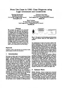
Figure 1. Multiple uses-relation between use cases
An example is given in Figure 1. Use case A has 4 subordinate use cases, each indicated with a (numeric) label. These components are A[1], A[7], A[3] and A[12]. The components lie on a path (a possible sequence) in use case A. Use case B has 3 components, and use case C has 5 components. Use case C is the using use case, and use cases A and B are the used use cases. The uses-relation between use cases is expressed by a list of tuples, in which the first component refers to the used label and the second component to the using label. A label refers to a one-entry one-exit use case component. All labels are assumed to be unique. The use case of the used label is placed onto the use case of the using label. If there is more than one path in a use case then the uses-relation should be defined for each path separately. We assume that interleaving has the following properties: 1. The resultant use case does not depend on the order in which the use cases are being used.
Control-Flow Semantics of Use Cases
page 10
2. The uses-relation between use cases preserves the order of the use cases involved, i.e. the order of components in the resulting use case corresponds to the order of the components in the using use cases and the used use cases. There are two conditions to be satisfied to obtain this order preserving interleaving of use cases: 1. The used labels in the uses-relation must lie on a path in the used use case; in other words they are a subsequence of the labels in the used case. 2. The using labels in the uses-relation must lie on a path in the using use case; in other words they are a subsequence of the labels in the using case. Furthermore, the using labels in the uses-relations must be unique, i.e. no using use case can use another use case more than once. The subsequence-condition can be shown in the expanded view on the uses-relation as given in Figure 2. In the view this condition means that uses-lines between using use case and used use cases should not cross. The resulting use case consists of A[7], C[10], B[2], A[3], B[5]. The two conditions are fulfilled and the order of components of all use cases involved is preserved.
C[9]
C[10]
C[4]
C[11]
C[6]
[3 on 11] [2 on 4]
[5 on 6]
[7 on 9]
A[1]
A[7]
A[3]
A[12]
B[2]
B[8]
B[5]
Figure 2. Expanded view on multiple uses-relation between use cases from Figure 1
4.
Control-flow in sequence diagrams
The flow of control in use cases can be displayed in interaction diagrams, especially the sequence diagrams. However, with branching the flow of control is not always obvious. We model branching through objects with auxiliary lifelines. Once the condition is not anymore
Control-Flow Semantics of Use Cases
page 11
determinative, the auxiliary lifeline is joined with the main lifeline. The values of the conditions are displayed at each branching point. The flow of control can be read quite easily now from the sequence diagrams as shown in Figure 3 and Figure 4. x : ClassX
entry
x’ : ClassX
c( )
begin of branching on condition c with two lifelines of x
[c = true] n1( ) n2( )
[c = false] n3( )
n4( ) end of branching on condition c
join lifelines
exit
Figure 3. Branching in a sequence diagram with auxiliary lifeline
In Figure 3 the value of condition c is established. If c is true then message n1 is sent to object x followed by sending n2, otherwise message n3 is sent to x followed by n4. In order to visualise these branches, object x’ is introduced. This object x’ is the same as object x, however with an own auxiliary lifeline. After sending n2 the flow of control is going back to the main lifeline of the object x. At sending n3 to object x, on the lifeline of x, there is an (implicit) assumption that condition c is false. We can map this sequence diagram onto flowgraphs. The corresponding flowgraph in this case is: x.c( ); IF(c,(x.n1( ); x.n2( )), (x.n3( ); x.n4)). Now, there are three types of arrows being used in sequence diagrams: with a message sent to the target object, a return value to the target object, and – as introduced above – solely the transfer of control to the target object (which is also implicit with the other arrows). Each of the arrows may have additionally a guard showing the condition on the flow of control. It is recommended to indicate the type of arrow being used in the diagrams (by adding the message name, return or join/merge/transfer respectively). Also other objects may be involved in branching. In Figure 4, again the value of condition c is established. If c is true then message m1 is sent to object y otherwise message m2 is sent to y.
Control-Flow Semantics of Use Cases
page 12
In order to visualise these branches, object y’ is introduced with an auxiliary lifeline. After sending m2 and m4 the flow of control is going back from the auxiliary lifeline to the main lifeline of object y. The corresponding flowgraph for this sequence diagram is: x.c( ); IF(c, (y.m1( ); y.m3( )), (y.m2( ); y.m4( ))). In this example, the flow of control ends at object y, which provides the exit point of the (partial) sequence diagram.
x : ClassX entry
begin of branching on condition c control transferred to object y with two lifelines
y : ClassY
y’ : ClassY
c( )
[c = true] m1( ) [c = false] m2( ) m4( ) m3( )
end of branching on condition c
join lifelines
exit
Figure 4. Branching in a sequence diagram to other object with auxiliary lifeline
4.1. Extension points in sequence diagrams In the use cases presented in the previous sections there are extension points for relations with other use cases. Usually, an extension point has to be added to a use case once the need for a relation with another use case becomes apparent. An extension point z in a sequence diagram may be modelled by some message sent to a (dummy) object z. If there is a condition on the relation then this will be indicated on the branches. It must be clear which part of the use case is involved in the extension as part of the branching. An example is given in Figure 5. The original use case just contains one message m sent to object x, being the ’normal’ course in the use case (part a of the figure). The extension of this use case in z is subject to condition c. The use case can be adapted for the extension with the branching IF c THEN z ELSE x.m( ) END (part b of the figure). The sequence diagram of the extending use case can be inserted on the extension point z (part c of the figure). In terms of flowgraphs, this is a nesting of the flowgraph of the extending use case onto the flowgraph of the original use case.
Control-Flow Semantics of Use Cases
x : ClassX
x : ClassX
entry
entry
page 13
x : ClassX
z:
entry
[c = true]
[c = true]
entry entry
[c = false ]
[c = false ] m( )
m( )
m( )
extending use case exit
exit
exit
part a
exit
part c
part b
Figure 5. A sequence diagram with a conditional extension point
The flow of control in use cases may also be described with UML-activity diagrams [2],[14]. The semantics of activity diagrams can be described in terms of control-flow graphs in a similar way as shown above for sequence diagrams. The rules for nesting and sequencing activity diagrams are the same as for control-flow graphs. An example activity diagram is given in Figure 6 for the sequence diagram in Figure 4.
x.c( )
test c
[ c = true ]
[ c = false ]
y.m1( )
y.m2( )
y.m3( )
y.m4( )
Figure 6. Activity diagram corresponding to sequence diagram in Figure 4
Control-Flow Semantics of Use Cases
5.
page 14
Conclusion and Guidelines
The control-flow semantics of use cases can be described in the well-established model of control-flow graphs. A prerequisite is that use cases have the one-entry one-exit property. If not then one may obtain unstructured use cases with an ill-defined flow of control, as the use of goto-statements in conventional programming may result in spaghetti-code. The control-flow of the extends-relation and uses-relation between use cases has been described in terms of nesting of flowgraphs; the precedes-relation is given as a sequencing of flowgraphs. It is shown that the uses-relation is semantically equivalent with an unconditional extends-relation. Parallel execution of use cases cannot be mapped onto standard flowgraphs.
use case
relation
control-flow semantics
•
common
uses
behaviour is inserted unconditionally
•
component
•
variant
extends
behaviour is inserted conditionally
•
specialised
•
ordered
precedes
behaviour is appended unconditionally
Table 4. Five kinds of use cases with their control-flow semantics
In Table 4 a summary is given of the control-flow semantics for the five kinds of use cases described in the first part of this paper. Both common use cases and component use cases have the control-flow semantics of the uses-relation between use cases, whereas variant uses cases and specialised use cases have the semantics of the extends-relation. Ordered use cases have the control-flow semantics of a precedes-relation in which behaviour is of one use case is sequenced (appended) to the behaviour of the preceding use case. Furthermore, we have augmented the notation for branching in sequence diagrams with auxiliary lifelines to visualise the flow of control. With the mapping of use cases onto flowgraphs, the corresponding theory of flowgraphs can be applied to the analysis of use case diagrams, among others with metrics for structuredness, complexity and testability.
Use cases may be used for deriving tests for the resulting software. The mapping onto flowgraphs allows the use of testability metrics for a number of test strategies: all-path testing,
Control-Flow Semantics of Use Cases
page 15
visit-each loop path testing, simple path testing, branch testing and statement testing. For structured flowgraphs the set can be derived from the component flowgraphs and the flowgraphs onto which they are nested [13]. For the analysis of flowgraphs there are several tools available, such as Prometrix and Qualms (for references, see Fenton & Pfleeger [13]). Metric values can be obtained with these tools. These static analysers need a front-end in which a flowgraph representation is derived, in this case from the sequence diagrams of use cases. Without such analysers, we have to derive tests based on the flow of control in use cases directly from sequence diagrams, for example in the Rational Rose tool. Then, such a tool should support conditional behaviour with branching or UML-defined activity diagrams.
From the analysis of use cases with flowgraphs given in this paper, seven guidelines are derived, which - once followed - facilitate reasoning about the flow of control in use cases and related sequence diagrams: •
Define for each use case and its sequence diagram both the entry point and the exit point. These points are prerequisites for a well-defined flow of control in use cases with usesrelationships and extends-relationships.
•
Give for each used use case (in a uses-relation) the precise extension point in the using use case.
•
Provide for each extending use case (in an extends-relation) an explicit if-then(-else) construct in the extended use case, together with the extension condition and the extension point, and - if applicable - the component in the normal use case for which the extension is an alternative.
•
Do not use precedence-forks from use cases (a use case followed by more than one use cases in a precedes-relation), unless explicit parallelism is required. If used then the related join use case should be provided.
•
Provide an if-then-else construct in the superordinate use case for selection of alternative component use cases, and a while construct for repetition of a component use case.
•
Model branching in sequence diagrams with auxiliary objects with their own temporary lifeline.
•
Label arrows between objects in sequence diagrams with either a message, a return or a join/merge.
Control-Flow Semantics of Use Cases
page 16
Acknowledgement This paper has been written during the first author’s sabbatical leave in the Department of Computer Science at the University of Sheffield, where the authors had many discussions on object-oriented modelling issues. The authors would like to thank Pim van den Broek for his comments on earlier versions of this paper. The paper also improved through the comments of the anonymous referees.
References [1] Jacobson, I., Christerson, M. Jonsson, P. & Övergaard, G. (1992). Object-Oriented Software Engineering, A Use Case Driven Approach. Addison-Wesley, Wokingham [2] Rational (1997). UML Summary, Semantics, Notation Guide, Version 1.1, Rational Software Corporation [3] Jacobson, I, Griss, M. & Jonsson, P. (1997). Software Reuse. Architecture, Process and Organization for Business Success. Addison Wesley Longman [4] Berard, E.V. (1996). Be Careful With “Use Cases”. http://www.tao.com/pub/html/use_case.html [5] Cockburn, A. & Fowler, M. (1998). Question Time! about Use Cases. OOPSLA’98. ACM Sigplan Notices 33(10) 226-229. [6] Bergner, K., Raush, A. & Sihling, M. (1998). A Critical Look upon UML 1.0. In: Schader & Korthaus (Eds.) (1998). The Unified Modeling Language. Physica-Verlag, 92-97. [7] Övergaard, G. & Palmkvist, K. (1998). A Formal Approach to Use Cases and their Relationships. Workshop ' 98. http://www.it.kth.se/~gunnaro/www/index.html [8] Hsia, P.H., Samuel, J., Gao, J., Kung, D., Toyoshima, Y. & Chen, C. (1994). Formal Approach to Scenario Analysis. IEEE Software 11(2), March 1994, pp. 33-41 [9] Regnell, B., Andersson, M. & Bergstrand, J. (1996). A Hierarchical Use Case Model with Graphical Representation. Proceedings ECBS' 96, IEEE International Symposium and Workshop on Engineering of Computer-Based Systems. [10] Fenton, N.E. & Whitty, R.W. (1986). Axiomatic approach to software metrication through program decomposition, Computer Journal, vol. 29, no. 4, pp.329-339 [11] Graham, I. (1995). Migrating to Object Technology. Addison-Wesley, Wokingham
Control-Flow Semantics of Use Cases
page 17
[12] Firesmith, D., Henderson-Sellers, B. & Graham, I. (1997). OPEN Modeling Language (OML) Reference Manual. Sigs, New York [13] Fenton, N.E. & Pfleeger, S.L. (1996), Software Metrics, A Rigorous & Practical Approach. 2nd edition. Thomson, London [14] Fowler, M. & Scott, K. (1997). UML Distilled. Applying the Standard Object Modeling Language. Addison-Wesley, Reading. [15] Booch, G. Rumbaugh, J. & Jacobson, I. (1999). The Unified Modeling Language User Guide. Addison Wesley Longman
Appendix In the emerging version of UML 1.2 and 1.3 some major changes are expected with respect to use cases. Rational profoundly changed the description of the relations between Use Cases in UML version 1.2 (and 1.3) as compared to version 1.1. The new description can be found in Booch et al. [15], pp. 226/8. In UML version 1.1 (as described in this paper): 1. The relation between use cases was described as specialisation but was actually modelling variant behaviour 2. The generalisation relation was abused for both the and the relation between use cases 3. There was no (proper) specialisation relation between use cases
In the new UML version 1.2 / 1.3: 1. The old is now replaced by . It models common behaviour. It is denoted by a dependency relation between use cases with the arrowhead pointing to the included use case (compare the OML invokes) 2. The new is now used to model variant behaviour. It is denoted by a dependency relation between use cases with the arrowhead pointing to the extended use case 3. There is a (proper) specialisation relation between use cases denoted by the generalisation relation with the (open) arrowhead pointing to the general use case.
The new situation leads to Table 5 (the revision of Table 4 presented in this paper)
Control-Flow Semantics of Use Cases
page 18
use case
relation
control-flow semantics
•
common
includes
behaviour is inserted unconditionally
•
component
•
variant
extends
behaviour is inserted conditionally
•
specialised
generalisation
behaviour is replaced conditionally
•
ordered
precedes
behaviour is appended unconditionally
Table 5. Five kinds of use cases with their control-flow semantics (from UML 1.2/1.3)