6 Internat onal Workshop on Advanced Mot on Control
COMMAND GE NE RAT I ON WI T H SL I DI NG MODE CONT ROL F OR F L E XI B L E SYST E MS Erika A. Ooten
William Singhose
Department of Mechanical Engineering Georgia Institute of Technology Atlanta, GA 30332 USA
[email protected]
Department of Mechanical Engineering Georgia Institute of Technology Atlanta, GA 30332 USA
[email protected]
Abstract
arbitrary point away from the sliding manifold, it will always move toward it. As a result, if the system is not on the desired trajectory, the system will always move towards the desired trajectory. First order systems are fundamentally easier to control; therefore, the basis of a sliding mode controller is to replace nth-order systems with an equivalent first-order system. Mathematically, the sliding manifold, or sliding surface, is characterized by the variable, s , and is defined as:
Modeling inaccuracies can have adverse affects on a control system of a system, especially when there are significant flexible dynamics. Sliding mode control can provide good trajectory tracking of such systems, even in the presence of disturbances. Command generation has proven beneficial for eliminating residual vibration from motioninduced dynamics. In an attempt to utilize the best aspects of these two control methods, this paper proposes a control scheme that combines command generation and sliding mode control.
1. Introduction Modeling inaccuracies can have adverse affects on the control of a flexible system. Many control schemes have been proposed to deal with the unwanted dynamic response arising from both intended motion and unintended disturbances. Sliding mode control has received much attention for its ability to reject disturbances while tracking a desired trajectory. Command generation methods have recently become popular due to their ability to cancel motion-induced vibration in a simple way. This paper suggests the approach of adding a command generator to a sliding mode controller. The main purpose of sliding mode control is to reject disturbances and to remain insensitive to parameter perturbations [1]. According to [2], sliding mode control can produce perfect trajectory tracking even in the presence of parameter uncertainties. The price for perfect trajectory tracking is high actuator effort. In order to keep the system response along the desired trajectory, the actuator is forced to rapidly switch directions resulting in chatter. The chattering of the actuator may excite some unmodeled high frequencies in the system. There have been many proposed solutions to compensate for the excitation of these modes [3]. Among these solutions is a piece-wise continuous approximation of the discontinuous control law. Instead of jumping directly across the manifold, the discontinuous control law is replaced by one that moves smoothly across a boundary layer of the sliding manifold boundary. Often times a linear approximation of the jump discontinuity is used [1]. The sliding manifold is defined as the manifold of the state-space of system along which the sliding mode occurs [1]. It has been proven that if the system trajectories point towards the sliding manifold, the system will move toward the sliding manifold. Once on the manifold, ideally the system will remain on the manifold for all time. The initial conditions of the system, and the desired trajectory must lie on the sliding manifold; therefore, if the system starts at any
n −1 d s( x;t ) = + λ x˜ dt
(1)
where,
x˜ = x − x d (2) x = states of system xd = desired states λ = arbitrary positive constant n = number of states The scalar variable s represents a measure of the tracking performance of the system. The problem of forcing the system to track a specific trajectory is mathematically stated as keeping s(t) = 0 for all time. This is achieved by choosing a control law u, such that when the system is off the sliding manifold 1 d 2 s ≤ −ηs 2 dt
(3)
where η is an arbitrary positive constant. Equation (3) is the sliding condition. The sliding condition states that the squared distance from the system’s states to the sliding manifold must decrease along any of the of the system’s trajectories. Satisfying (3) makes the sliding manifold an invariant set. Defining the trajectories of the system from (1), and satisfying the sliding condition, makes the solution of tracking the desired trajectory an invariant set. This allows us to replace an nth-order system with a scalar firstorder system. The mathematics of the nth order system are reduced to keeping the scalar quantity s equal to zero for all t>0 [2]. As a result, the control law, u, is found by solving the following equation s˙ ≡ 0 (4) The expression for u is called the equivalent control law and is composed of a continuous control law approximation, û, and a discontinuous term, ksgn(s): u = uˆ − ksgn(s) (5) The implementation of a sliding mode controller gets progressively more difficult as the number states increases. It is further complicated when these additional states are
H
H
0
Time Original Command
*
0
∆
0
Input Shaper
∆
Time
Shaped Command
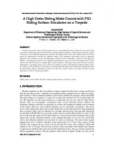
Figure 1: Input Shaping a Step Input. associated with uncertain flexible modes. To improve the performance under these conditions, a command generator can be added to a simplified sliding mode control scheme. Command generation attempts to eliminate the detrimental effects of flexibility by producing a command profile that negates the unwanted dynamics. Input shaping is one type of command generation that has proven successful on many types of applications. Input shaping is implemented by convolving a sequence of impulses, called the input shaper, with a desired system command. The convolved signal is then used as the reference command. Figure 1 demonstrates this process starting with an unshaped command that is a step input and then convolving it with an input shaper that contains three positive impulses. The resulting shaped input is a three-step staircase command. If the impulse sequence causes no residual vibration when applied to the system, then the shaped input will also cause no residual vibration [4]. In general, only a simple system model consisting of estimates of the natural frequencies and damping ratios is used to design input shapers. The engineering challenge is to design an input shaper so that a desired set of performance specifications is achieved. Note in Figure 1 that the shaping process increases the command rise-time by the duration of the shaper, ∆. Therefore, making the shaper as short as possible is often an important design consideration. A shaper can be significantly shortened, while still maintaining the desired vibration reduction, by allowing the shaper to contain negative impulses [5]. An early form of input shaping, known as posicast control, was developed in the 1950’s [6-8]. Unfortunately, posicast control is sensitive to modeling errors; small modeling errors lead to significant levels of residual vibration. Input shaping became a useful tool for many real systems when a method for incorporating robustness was developed [4]. Input shaping has been implemented on a variety of systems. Residual vibrations of long-reach manipulators [9, 10], cranes [11-15], and silicon-handling machines [16, 17] were decreased with input shaping. Furthermore, the performance of coordinate measuring machines was improved with input shaping [18-20]. Shaping was combined with a post-maneuver damping controller to improve large angle slewing [21]. Although input shaping was developed to reduce residual vibration, it has also proven beneficial for trajectory following applications [22, 23]. Given these trajectory following results, it seems natural to combine input shaping with a sliding mode controller. This paper shows preliminary results that indicate such a control architecture provides very good performance. The
x1(t) u(t) m1
k1 b
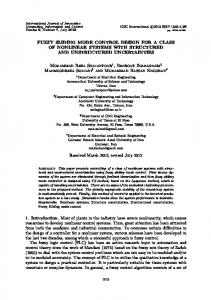
Figure 2: Spring-Mass-Damper System. next section describes the model that is used to demonstrate the control scheme. Section 3 presents simulation results and Section 4 makes conclusions based on the simulation results.
2. Model Description The model that the sliding mode is based on is a single mass spring damper system shown in Figure 2. The dynamics of the system can be described by two states and can be represented as:
x˙ 1 1 0 x˙ = m −k 1 2 1
1 x1 0 + u −b x 2 1
(6)
Following equation (1), the sliding manifold for the system shown in Figure 2 is calculated as:
s˙ = ˙˙ x˜ 1 + λx˜˙ 1
(7)
Using equation (5), the equivalent control law, u, is
u = k1x1 + bx˙ 1 + m1˙˙ x1d − λm1x˜ 1 − ksgn s
(8) The sliding condition that is used as the basis for determining the discontinuous part of the control law is [2]: k=F+η (9) where F is the estimation error of the system. The desired motion of the system is chosen to be a ramp-rest-return trajectory. The system moves to the desired new location, waits a specified amount of time, and then returns to the original location. Figure 3 shows the response of the secondorder system tracking the desired ramp-rest-return trajectory. The system follows the desired trajectory with little error. It is important to note that λ equals 50 for this case. Referring to (8), it can be seen that the price for better trajectory tracking, is an increase in actuator effort. The error was calculated as follows error = x − x d (10)
5
4
4
Position
Position
5 3 2 System Response
1
0
Desired Trajectory
0
0
2
4
6
8
-1
10
Time (sec)
λ=5 λ = 10 λ = 25 λ = 50
2
1
-1
0
2
0.2
0
-0.1 -0.2 2
4
6
6
8
10
Figure 5: System Response as a function of λ.
2 1.5 1 0.5 0 -0.5 -1 -1.5 -2
λ=5 λ = 10 λ = 25 λ = 50
Error
0.1
0
4
Time (sec)
Figure 3: Response of Example System under Sliding Mode Control.
Error
3
8
10
Time (sec)
0
2
3. Simulation of Sliding Mode Control with Command Generation Figure 7 shows the system used in simulations. The system is the same spring-mass-damper system as in the previous example; however, an additional mass and spring
6
8
10
Figure 6: Tracking Error for Different Values of λ.
Figure 4: Tracking Error for the Example System under Sliding Mode Control. Figure 4 shows the error for the system response. It can be seen that the sliding mode controller does eventually reach the desired trajectory. There are several different parameters that can affect how well the system tracks the desired trajectory. One of the parameters that has a significant impact in trajectory tracking error, is the arbitrary positive constant λ. Figure 5 shows how the response of the example system is affected by changing the value of λ. The smaller the value of λ, the greater the tracking error. As λ decreases, the system responds slower to a change in the desired trajectory, and eventually, the system response will no longer reach the desired trajectory. This trend can be seen in Figure 5. As λ decreases in value, the difference between the system response and the desired trajectory increases. The control law is based on the systems response, and the difference between the actual and desired velocity. When the desired trajectory is in the rest period, the desired velocity is zero. The sliding mode controller forces the systems velocity to zero before the system reaches the desired position; consequently, the system never reaches the desired position. The change in tracking error as a function of λ is shown in Figure 6. The next section discusses the response of the example system when a disturbance is introduced.
4
Time (sec)
x1(t)
x2(t)
u(t) k1
m1
k2
m1
b Figure 7: Flexible Example System Table 1: Example System Parameters Parameter Value m1 5 m2 2 k1 100 k2 78.96 b 0 λ 10 η 0.1 F 0.1 were added in order to introduce more complicated dynamics. The sliding mode controller developed in the previous section is used to control this more complicated system. The frequency of the additional mode is 1 Hz. Table 1 lists the baseline parameter values used in the simulations. The first simulation used only the sliding mode as the control input to the system. The desired trajectory for X1(t)
3
4
2
3
1
Error
Position
5
2 1
System Response
0
Desired Trajectory
-1
0
2
4
-2 6
8
10
0
2
4
10
5
1
4
Position
0.5 0
-0.5 -1 0
2
4
6
8
3 2 1
System Response
0
Shaped Trajectory
-1
10
0
2
4
Time (sec)
1.5
4
Error
λ=5 λ = 10 λ = 25 λ = 50
1
10
λ=5 λ = 10 λ = 25 λ = 50
1
2
8
Figure 12: Flexible System Response to Shaped Trajectory.
5 3
6
Time (sec)
Figure 9: Tracking Error for Flexible System Using Only Sliding Mode Control.
Position
8
Figure 11: Tracking Error as a Function of λ.
1.5
0.5 0
-0.5 -1
0 -1
6
Time (sec)
Figure 8: Flexible System Response Using Only Sliding Mode Control.
Error
0 -1
Time (sec)
-1.5
λ=5 λ = 10 λ = 25 λ = 50
0
2
4
6
8
10
Time (sec)
-1.5
0
2
4
6
8
10
Time (sec)
Figure 10: System Response as a Function of λ.
Figure 13: Shaped Trajectory Error as a Function of λ.
was the same ramp-rest-return path used in the preceding section. Figure 8 shows the response of the system. It can be seen that the system oscillates at a frequency of 1 Hz resulting from the additional flexible mode introduced into the system. The tracking error for the system response can be seen in Figure 9. The error for the flexible system is significantly larger than the error for the simpler system for the same value of λ. Increasing the λ does has a reducing effect on the tracking error for the system. It does not; however, eliminate the oscillations as seen in Figure 10. As stated earlier, the higher the λ, the higher the actuation effort. Figure 11 shows the decrease in the error corresponding to the higher values of λ. A Zero Vibration [4-6] input shaper was designed to eliminate the oscillations resulting from the additional flexible mode. The desired trajectory of the system was then
convolved with the shaper to produce a shaped trajectory. Instead of following the unshaped trajectory, the system was given the shaped path to follow. Figure 12 shows the response of the system following the shaped trajectory. By comparing Figure 10 to Figure 12 it can be seen that the shaped trajectory cancels out the oscillations resulting from the addition mass and spring. The price for the canceling out the residual vibration is a slight increase in the move time. As with the system response following the unshaped trajectory, the shaped trajectory tracking error can be improved by increasing the value of λ. Figure 13 shows the tracking error corresponding to changes in λ. Figure 14 compares the unshaped trajectory tracking error to the shaped trajectory tracking error. The error corresponding to the shaped trajectory is smaller than for the unshaped case.
Unshaped Error
0.4
Shaped Error
Error
0.2 0
-0.2 -0.4 0
2
4
6
8
10
Time (sec) Figure 14: Shaped vs. Unshaped Tracking Error A smaller overall error corresponds to a decrease in actuator effort, since the control law is based on the difference between the actual and desired velocities.
4. Conclusions It has been shown in this paper that a control scheme that incorporates an input shaper with a sliding mode controller can increase the tracking performance of a system with flexible dynamics. The overall error for the system following the shaped path is much smaller than for the same system following an unshaped path. The price for improving the tracking performance is an increase in the rise time of the system. However, when the rise time of the system is very small compared to the entire maneuver length, then the increase in rise time may be insignificant. The increase in the rise time is directly dependent on the type of shaper used. It may appear that tracking errors can be improved when using only a sliding mode controller by simply increasing the value of λ. However, the improvement in performance comes at the cost of increased actuator effort. The increase in actuator effort is not readily apparent from the response of the system, and care must be taken in order to avoid actuator saturation. The improvement in trajectory tracking that occurs when implementing both a sliding mode controller and an input shaper does not require an increase in actuator effort.
References (1) Young, K.D., V.I. Utkin, and U. Ozguner, A Control Engineer's Guide to Sliding Mode Control. IEEE Transactions on Control Systems Technology, 1999. 7(3): p. 328-342. (2) Slotine, J.J. and W. Li, Applied Nonlinear Control. 1991, Englewood Cliffs, NJ: Prentice-Hall, Inc. (3) Slotine, J.-J. and S.S. Sastry, Tracking Control of NonLinear Systems Using Sliding Surfaces, with Applications to Robot Manipulators. Int. J. of Control, 1983. 38(2): p. 465492. (4) Singer, N.C. and W.P. Seering, Preshaping Command Inputs to Reduce System Vibration. J. of Dynamic Sys., Measurement, and Control, 1990. 112(March): p. 76-82. (5) Singhose, W., N. Singer, and W. Seering, T i m eOptimal Negative Input Shapers. J. of Dynamic Systems, Measurement, and Control, 1997. 119(June): p. 198-205. (6) Smith, O.J.M., Posicast Control of Damped Oscillatory Systems. Proceedings of the IRE, 1957. 4 5(September): p. 1249-1255.
(7) Smith, O.J.M., Feedback Control Systems. 1958, New York: McGraw-Hill Book Co., Inc. 331-345. (8) Tallman, G.H. and O.J.M. Smith, Analog Study of Dead-Beat Posicast Control. IRE Transactions on Automatic Control, 1958(March): p. 14-21. (9) Jansen, J.F., Control and Analysis of a Single-Link Flexible Beam with Experimental Verification, . 1992, Oak Ridge National Laboratory. (10) Magee, D.P. and W.J. Book. Filtering MicroManipulator Wrist Commands to Prevent Flexible Base Motion. in American Control Conf. 1995. Seattle, WA. (11) Feddema, J.T. Digital Filter Control of Remotely Operated Flexible Robotic Structures. in American Control Conf. 1993. San Francisco, CA: ACC. (12) Kress, R.L., J.F. Jansen, and M.W. Noakes. Experimental Implementation of a Robust DampedOscillation Control Algorithm on a Full Sized, Two-DOF, AC Induction Motor-Driven Crane. in 5th ISRAM. 1994. Maui, HA. (13) Singer, N., W. Singhose, and E. Kriikku. An Input Shaping Controller Enabling Cranes to Move Without Sway. in ANS 7th Topical Meeting on Robotics and Remote Systems. 1997. Augusta, GA. (14) Noakes, M.W. and J.F. Jansen, Generalized Inputs for Damped-Vibration Control of Suspended Payloads. Robotics and Autonomous Systems, 1992. 10 (2): p. 199-205. (15) Kennison, M. and W. Singhose. Input Shaper Design for Double-Pendulum Planar Gantry Cranes. in IEEE Conference on Control Applications. 1999. Hawaii. (16) Rappole, B.W., N.C. Singer, and W.P. Seering. Multiple-Mode Impulse Shaping Sequences for Reducing Residual Vibrations. in 23rd Biennial Mechanisms Conference. 1994. Minneapolis, MN. (17) Roover, D.d., F.B. Sperling, and O.H. Bosgra. Point-toPoint Control of a MIMO Servomechanism. in American Control Conference. 1998. Philadelphia, PA. (18) Jones, S.D. and A.G. Ulsoy. Control Input Shaping for Coordinate Measuring Machines. in American Control Conf. 1994. Baltimore, MD: ACC. (19) Seth, N., K. Rattan, and R. Brandstetter. Vibration Control of a Coordinate Measuring Machine. in IEEE Conf. on Control Apps. 1993. Dayton, OH. (20) Singhose, W., N. Singer, and W. Seering, Improving Repeatability of Coordinate Measuring Machines with Shaped Command Signals. Precision Engineering, 1996. 18 (April): p. 138-146. (21) Hillsley, K.L. and S. Yurkovich, Vibration Control of a Two-Link Flexible Robot Arm. J. of Dynamics and Control, 1993. 3 : p. 261-280. (22) Drapeau, V. and D. Wang. Verification of a Closedloop Shaped-input Controller for a Five-bar-linkage Manipulator. in IEEE Int. Conf. on Robotics and Automation. 1993. Atlanta, GA: IEEE. (23) Singhose, W. and N. Singer, Effects of Input Shaping on Two-Dimensional Trajectory Following. IEEE Trans. on Robotics and Automation, 1996. 12(6): p. 881-887.