functional unit input or output is connected by a dedicated bus to a dedicated ... nect inside the register files with explicit interconnect managed by the compiler.
Communication Scheduling Peter Mattson, William J. Dally, Scott Rixner, Ujval J. Kapasi, John D. Owens Computer Systems Laboratory Stanford University Stanford, CA 94305
{pmattson, billd, rixner, ujk, jowens} @ cva.stanford.edu ABSTRACT The high arithmetic rates of media processing applications require architectures with tens to hundreds of functional units, multiple register files, and explicit interconnect between functional units and register files. Communication scheduling enables scheduling to these emerging architectures, including those that use shared buses and register file ports. Scheduling to these shared interconnect architectures is difficult because it requires simultaneously allocating functional units to operations and buses and register file ports to the communications between operations. Prior VLIW scheduling algorithms are limited to clustered register file architectures with no shared buses or register file ports. Communication scheduling extends the range of target architectures by making each communication explicit and decomposing it into three components: a write stub, zero or more copy operations, and a read stub. Communication scheduling allows media processing kernels to achieve 98% of the performance of a central register file architecture on a distributed register file architecture with only 9% of the area, 6% of the power consumption, and 37% of the access delay, and 120% of the performance of a clustered register file architecture on a distributed register file architecture with 56% of the area and 50% of the power consumption.
FIGURE 1. Central register file
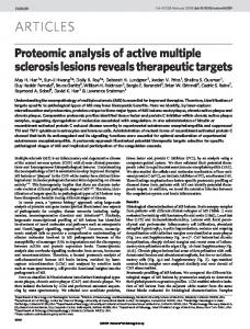
FIGURE 2. Clustered register files shared buses
shared buses
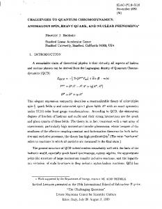
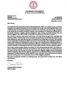
1. INTRODUCTION Media processing applications, such as video compression and decompression, image synthesis, and image understanding, demand very high arithmetic rates. Currently, these applications demand from 1010 to 1011 operations per second [5]. As these applications become more sophisticated, even higher rates are expected. To achieve these high arithmetic rates, processor architectures with tens to hundreds of functional units are required. The dominant cost in such an architecture is interconnect between functional units, not computation or storage. Traditionally, every functional unit input or output is connected by a dedicated bus to a dedicated register file port of a central register file as shown in Figure1. The central register file scales poorly with large numbers of functional units [1][2][11] because each register contains an implicit interconnect from every functional unit output to every functional unit input. For N functional units, the area of a central register file grows as N3 , the power dissipation as N3 , and the access delay as N3/2 [15].
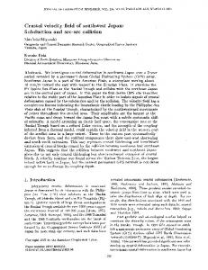
FIGURE 3. Multiple register files with shared interconnect To build an efficient architecture with tens to hundreds of functional units, the implicit interconnect of a central register file needs to be replaced with multiple register files and external interconnect managed by the compiler. A clustered register file architecture, which divides the functional units into clusters and provides each cluster with its own register file as shown in Figure2, is one step in this direction. However, each functional unit input or output is still connected by a dedicated bus and register file port to the cluster register file, which contains implicit interconnect between all functional units in the cluster. The compiler must insert copy operations to move values between cluster register files across a set of global buses. The non-zero latency of these copy operations decreases performance. In the most efficient multiple register file architectures, functional unit inputs and/or outputs are connected directly to multiple register files using shared buses and register file ports as shown in Figure3. These architectures replace most or all implicit interconnect inside the register files with explicit interconnect managed by the compiler. Since functional units can read from and/or write to multiple register files directly, the performance impact of copying values between register files is significantly reduced. Scheduling to these shared interconnect architectures is difficult because the compiler must simultaneously allocate many interdependent resources: the functional units on which the operations take place, the register file(s) to stage intermediate values through, and the shared interconnect to transfer the values between functional units and register files. Each of these resource allocation
Most prior VLIW scheduling algorithms [1][4][6][12][13] are restricted to architectures in which each functional unit input or output is connected by a dedicated bus and register file port to one register file. All operations scheduled on the functional unit must read values from and write values to that register file. The compiler can schedule operations without allocating shared interconnect, then insert copy operations that take place on dedicated copy units to move values between register files. Some VLIW scheduling algorithms [3][7][14][17] target specific architectures that allow limited access to multiple register files by overprovisioning interconnect to avoid resource conflicts. Communication scheduling is a new component of VLIW scheduling that enables scheduling to a large class of architectures in which each functional unit input or output is connected to multiple registers files by shared buses and register file ports. Communication scheduling selects register files and allocates interconnect incrementally as each operation is scheduled. When the first of two communicating operations is scheduled, communication scheduling tentatively allocates interconnect to write the value to or read the value from a register file. Communication scheduling may change the initial allocation as other operations are scheduled. When the second operation is scheduled, communication scheduling selects a register file to stage the value through and allocates all shared interconnect. In particular, communication scheduling enables scheduling to a distributed register file architecture that offers better performance and lower area, power consumption, and register file access delay than a clustered register file architecture. In a distributed register file architecture each functional unit input is connected to the single read port of a dedicated register file and all functional unit outputs are connected by shared buses to the single shared write port of each register file. Such an architecture with N arithmetic units has area that grows as N2, power dissipation that grows as N2 , and delay that grows as N [15]. For a distributed register file architecture with 12 functional units, communication scheduling allows media processing kernels to achieve 120% of the performance of a clustered register file architecture with the same twelve functional units, or 98% of the performance of a central register file architecture. However, the distributed register file architecture requires only 56% as much area and 50% as much power as the clustered register file architecture, or 9% as much area and 6% as much power as a central register file architecture. This paper describes how communication scheduling enables scheduling for shared interconnect architectures. Section2 presents a motivating example. Section3 presents an overview of communication scheduling. Section4 describes communication scheduling in detail. Section5 presents and discusses our results. Section6 and Section7 discuss prior and future work, respectively. Section8 summarizes our conclusions.
interconnect that require communication scheduling. Each adder output and the load/store unit output is connected by a shared bus to two register files. Both of the shared buses can drive the shared write port of the center register file.
1: 2: 3: 4: 5:
a = b = c = ... ...
load ... ... + ... ... + ... = a + b = a + c
FIGURE 4. Example code fragment
ADD0
L/S
either output can drive shared bus
ADD1
output can drive either or both buses
either bus can drive shared port
FIGURE 5. Example architecture Figure6 shows an incomplete and incorrect schedule1 produced by a conventional scheduler that does not allocate shared interconnect. The schedule in Figure6 is incomplete because it does not specify which output drives each shared bus or which bus drives the shared register file port on each cycle. It is incorrect because operation 1 and operation 2 both need to write to the same register file using the same bus in order to allow operation 4 to occur on the next cycle. This problem demonstrates that scheduling operations and allocating interconnect cannot be performed independently. Functional Unit ADD0
L/S
ADD1
1
1: b = ... + ...
2: a = load ...
3: c = ... + ...
2
4: ... = a+b
Cycle
steps is dependent on the others. For example, efficiently selecting a register file and allocating interconnect to communicate a value from the operation that computes it to an operation that uses it depends on which functional unit both operations are scheduled on. Thus, the scheduler cannot select a register file or allocate interconnect when scheduling the first of the two communicating operations. However, if the scheduler does not allocate interconnect until scheduling the second operation, other communications may occupy all of the required interconnect during the interim making it impossible to schedule the operation.
5: ... = a+c
FIGURE 6. Schedule without allocation of shared interconnect Figure7 shows a schedule produced by a scheduler that uses communication scheduling to allocate shared interconnect. Constructing the schedule in Figure7 provides examples throughout the rest of this paper.
2. MOTIVATING EXAMPLE Scheduling the code fragment shown in Figure4 to the architecture shown in Figure5 demonstrates that a conventional scheduler cannot schedule to an architecture with shared interconnect. Though simple and purposefully non-optimal, the architecture includes all of the features of a multiple register file architecture with shared
1. For illustrative purposes, all operations have unit latency.
functional unit that uses it, and, if necessary, copy operation(s) to move the value between register files.
Functional Unit ADD0
1
L/S
ADD1
The motivating example contains four communications as shown in Figure9 and four routes, one for each communication, as shown in Figure10. For example, operation 1 computes the value a, which is used by operation 4 and operation 5. There are two communications from operation 1, one to operation 4 and one to operation 5, each of which is assigned to a route.
1: b = ... + ...
2: a = load ...
b
a
a
a= copy a
3: c = ... + ...
Cycle
1: a = load ... 2
3
2: b = ... + ...
1
2
a
a
c
4: ... = a+b
5: ... = a+c
1
A VLIW scheduler assigns each operation to a functional unit and schedules it on a particular cycle; communication scheduling allocates the interconnect resources the operation uses to read its operands and write its result. Communication scheduling allocates resources such that the result of an operation is accessible to all operations that use that result as an operand. To achieve this objective, communication scheduling assigns each communication between operations to a route between the functional units that perform those operations as depicted in Figure8.
write operation
Cycle
3. OVERVIEW
5: ... = a + c
ADD0
Functional Unit L/S
2: b = ... + ...
1: a = load ...
b
a 1
a= 1 copy a
2
ADD1
a
3: c = ... + ... 2
3
3
b 1 a
a
4: ... = a+b
5: ... = a+c
c
4
FIGURE 10. Routes for communications in motivating example
4. COMMUNICATION SCHEDULING
result route
communication
4
FIGURE 9. Communications in motivating example
FIGURE 7. Schedule with allocation of shared interconnect
write operation
3
4: ... = a + b
b
3: c = ... + ...
operand
4.1 Use in a scheduler read operation
read operation
FIGURE 8. Communication scheduling assigns each communication to a route A communication is a scheduler abstraction for the use of the result of one operation as an operand of another operation. A communication exists from the write operation that computes a result to each read operation that could use the result as an operand. If multiple operations could use the result as an operand, or one operation could use the result as multiple operands, then a separate communication exists for each such read operand. If an operation could use one of several results as an operand due to different control flows then a separate communication exists for each such result. A route defines the resources used to transfer a value from a functional unit output to a functional unit input. A route consists of resources to write the value to a register file from the functional unit that computes it, resources to read it from a register to the
A VLIW scheduler with communication scheduling operates by scheduling an operation on a cycle and assigning it to a functional unit, then allowing communication scheduling to accept or reject the placement. Figure11 presents a flow graph of a scheduler that includes communication scheduling. This scheduler is loosely based on the algorithm presented in [13], but communication scheduling can be integrated into other algorithms. The algorithm selects an operation and schedules it on the first possible cycle. It then assigns the operation to an available functional unit and attempts communication scheduling. If communication scheduling succeeds, the operation is scheduled. If communication scheduling fails, the scheduler assigns the operation to a different functional unit, or delays it until a later cycle, until it succeeds.
4.2 Algorithm Communication scheduling composes a route for each communication as shown in Figure12. The write stub consists of the functional unit output, bus, and register file write port allocated to write the result. The write stub is allocated on the cycle that the writing
ADD0
Are there any unscheduled operations? Yes
Functional Unit L/S
ADD1
No
Tentatively schedule operation on first possible cycle
1: a = load ...
1
Select an operation
Tentatively schedule operation on next cycle
write stub
a
Yes
Cycle
Is there an untried available functional unit that can perform the operation? No
copy operation
a= copy a
2
Tentatively assign operation to that functional unit
read stub
a
Attempt communication scheduling
3
4: ... = a+b
Did communication scheduling succeed? Yes
No
Operation is scheduled!
FIGURE 11. Scheduler flow graph operation completes. The read stub consists of the register file read port, bus, and functional unit input allocated to read the operand. The read stub is allocated on the cycle that reading operation issues. If the write stub and read stub access the same register file, they form a route. Otherwise, one or more copy operations are used to move the value from one register file to another to connect the stubs and form a route.
write operation
write operation write stub
output bus
result
route
copy operation(s)
communication
write port
copy operation
FIGURE 13. Composition of route for communication of a from operation 1 to operation 4 first communicating operation is being scheduled, the communication is opening: communication scheduling determines the valid stubs and selects a stub that does not conflict with other stubs on the same cycle. Often, other operations are scheduled before the second operation is scheduled. As each such operation is scheduled, communication scheduling may change the stub assigned to the open communication to allow stubs to be found for other communications. When the second communicating operation is being scheduled, the communication is closing: communication scheduling tries to find a write stub and a read stub that access the same register file to form a route. If necessary, it inserts and schedules copy operations to connect the stubs and form a route. Once a communication has been assigned to a route it is closed and the stubs and any copy operations that compose the route cannot be changed.
current operation
scheduled operation
unscheduled operation
unscheduled operation
opening
open
scheduled operation
scheduled operation
current operation
scheduled operation
closing
closed
read port bus
read stub
operand
input read operation
read operation
FIGURE 12. Composition of a route Figure13 shows the write stub, read stub, and copy operation that compose the route for the communication of a from operation 1 to operation 4 in the motivating example. Communication scheduling composes routes such that stubs on the same cycle do not conflict. Read stubs for different operands or write stubs for different results conflict if they use the same resource, such as a functional unit input or output, bus, or register file port. An operand can only be read from one register file, so two read stubs for the same operand conflict if they are not identical. A result can be written to multiple register files, so two write stubs for the same result only conflict if they write to the same register file using different buses or register file ports. Communication scheduling composes a non-conflicting route for each communication incrementally as each of the two communicating operations are scheduled as shown in Figure14. When the
FIGURE 14. Incremental composition of a route
4.3 Implementation To implement this process, communication scheduling performs the following steps for each operation o, described in detail in the remainder of this section: 1.
determine the valid read stubs for each communication to o and the valid write stubs for each communication from o find a non-conflicting permutation of read stubs for communications to operations on the cycle o issues on find a non-conflicting permutation of write stubs for communications from operations on the cycle o completes on for each closing communication, if the read stub and write stub form a route then assign the communication to that route for each closing communication, if the read stub and write stub do not form a route then insert and attempt to schedule copy operation(s) to connect the stubs
2. 3.
4.
5.
Step 1. Determine valid stubs First, communication scheduling determines the valid read stubs for each communication to the current operation, and the valid write stubs for each communication from the current operation. A read stub connects a read port of a register file to an appropriate input of the functional unit that the current operation is assigned to. A write stub connects the output of the functional unit that the current operation is assigned to the write port of a register file. For a communication from operation o1 to operation o2 , zero or more copy operations can be used to move a value from any register file written to by a valid write stub for o1 to any register file read from by a valid read stub for o2 , regardless of which functional units the operations are assigned to.1 Figure15 shows the valid write stubs, and Figure16 shows the valid read stubs, for the communication of a from operation 1 to operation 4 in the motivating example. Zero or more copy operations can be used to connect any write stub in Figure15 to any read stub in Figure16. ADD0
ADD1
1: a = load ...
1
ADD0
1
L/S
L/S
1: a = load ...
ADD0
ADD0
1
ADD1
1: a = load ...
1
ADD1
L/S
L/S
3
4: ... = a+b
3
4: ... = a+b
FIGURE 16. Valid read stubs
Step 2. Find permutation of read stubs Second, communication scheduling attempts to find a permutation of read stubs for the set of communications to all operations that issue on the same cycle as the current operation, Cto , such that the stubs do not conflict. (Cto includes all communications to the current operation.) Since communication scheduling can't change the read stub assigned to a closed communication, it removes all closed communications from Cto . It eliminates all valid stubs for the remaining communications that conflict with any read stub assigned to a closed communication. Communication scheduling then attempts to find a valid stub for each communication remaining in Cto . It can choose any stub for each open communication, but tries to choose a read stub for each closing communication that forms a route. When selecting a read stub for a closing communication c from a scheduled operation os, communication scheduling also attempts to find a permutation of write stubs for communications to operations that complete on the same cycle as os such that the write stub for c accesses the same register file as the read stub and forms a route.
Step 3. Find permutation of write stubs Third, communication scheduling analogously attempts to find a permutation of write stubs for all communications from operations that complete on the same cycle as the current operation, Cfrom . If communication scheduling cannot find permutation of read stubs or a permutation of write stubs, the current operation must be rescheduled. In the motivating example, communication scheduling finds different permutations of write stubs for the communications from operations on cycle 1 as each of the first two operations are scheduled. Communication scheduling chooses the permutation of write stubs shown in Figure17 when operation 1 is scheduled, then changes to the permutation shown in Figure18 when operation 2 is scheduled. Operation 3 cannot be scheduled on cycle 1 because a permutation of write stubs cannot be found due to stub conflicts as shown in Figure19.
ADD0
ADD1
L/S
ADD1
1: a = load ...
1
1: a = load ...
FIGURE 15. Valid write stubs FIGURE 17. Permutation of write stubs when scheduling operation 1
Step 4. Assign routes 1. AppendixA describes the class of copy-connected architectures that support this use of copy operations.
Fourth, communication scheduling examines each closing communication and assigns a route if possible. If the read stub and write
Step 5. Insert copy operations ADD0
1
L/S
2: b = ... + ...
ADD1
Fifth, communication scheduling inserts and attempts to schedule a copy operation to connect the stubs and form a route for each remaining closing communication. Inserting a copy operation is equivalent to the code transformation shown in Figure21.
1: a = load ...
x = ... ... ... = x ... FIGURE 18. Permutation of write stubs when scheduling operation 2
1
ADD0
L/S
ADD1
2: b = ... + ...
1: a = load ...
3: c = ... + ...
x = ... x’ = copy x ... ... = x’ ...
FIGURE 21. Copy operation code transformation Effectively, this transformation splits the original communication into two communications, one from the write operation to the copy operation, and one from the copy operation to the read operation as shown in Figure22. Communication scheduling then calls on the scheduler to schedule the copy operation.
When scheduling operation 4 in the motivating example, the write stub and a read stub form a route for the closing communication of b from operation 2, so communication scheduling immediately assigns it to that route as shown in Figure20. The stubs for the closing communication of a from operation 1 do not form a route.
Functional Unit
1
ADD0
L/S
2: b = ... + ...
1: a = load ...
ADD1
b
Cycle
stubs form a route
3: c = ... + ...
2
write operation two communications
FIGURE 19. Operation 3 cannot be scheduled due to stub conflicts stub access the same register file and form a route, communication scheduling immediately assigns the communication to that route.
original communication
write operation
copy operation
read operation
read operation
FIGURE 22. A copy operation effectively splits original communication into two communications The copy operation is scheduled just like any other operation, except that it must be scheduled on a cycle in the copy range of the original communication. If the write operation is before the read operation in the same basic block, the copy range is all cycles between the cycle on which the write operation completes and the cycle on which the read operation issues. Otherwise, the copy range is all cycles in the write operation's basic block after the write operation completes. These two cases are shown in Figure23. Multiple operations can compute a result that is used as an operand by the same read operation depending on control flow. Copy operations are conservatively restricted to the write operation’s basic block so that they do not overwrite the result of the other write operations. Basic block 1
Basic block 2
1
b
3
Cycle
4: ... = a+b
Copy range
2 3 4
FIGURE 20. Route for communication of b from operation 2 to operation 4
Basic block 2
read operation
same block
2 3
1 Cycle
5
write operation Copy range
stubs do not form a route
write operation
Cycle
1
2
read operation
different block
FIGURE 23. Copy ranges based on location of read operation
Communication scheduling treats the copy operation just like any other operation, so communication scheduling can recursively insert additional copy operations as needed. Returning to the motivating example, the stubs for the closing communication of a from operation 2 to operation 4 do not form a route, so communication scheduling inserts and attempts to schedule a copy operation as shown in Figure24.
1 copy operation completes route
ADD0
Functional Unit L/S
2: b = ... + ...
1: a = load ...
b
a
ADD1
on which it issues and completes, even if only by scheduling no additional operations on those cycles. One search algorithm that meets these requirements orders the communications, then finds the first stub for each communication that does not conflict with the stub found for a previous communication. If all stubs for a communication conflict with stubs found for a previous communications, the search falls backs to the first such communication and chooses a new stub. The search terminates when a stub has been found for each communication or after an arbitrary, relatively large, number of partial permutations have been tried. With this algorithm, the order of communications is important. If the stub required to form a route for a closing communication conflicts with the stub found for a previous communication then that stub will not be chosen and a route will not be formed. Thus, all closing communications are ordered before all open or opening communications. Closing communications are ordered by smallest copy range first, so that the communications with the fewest of cycles to schedule copy operations on have preference in choosing stubs to form routes.
Cycle
4.5 Algorithm Completion a= copy a
2
3: c = ... + ...
b a
3
4: ... = a+b
FIGURE 24. Route for communication of a from operation 1 to operation 4 Communication scheduling succeeds if it finds a permutation of write stubs and a permutation of read stubs, and assigns each closing communication to a route. If communication scheduling fails, any routes assigned to communications to/from the current operation are unassigned, and any copy operations are unscheduled. The scheduler then reschedules the operation and attempts communication scheduling again. Once all operations have been scheduled successfully, communication scheduling has assigned all communications to routes.
4.4 Stub Permutation Search The number of permutations of valid stubs for a set of communications is exponential with the number of communications. However, the permutation search does not need to examine all permutations. The search is sufficient if:
• •
It can find a read/write stub for all communications to/ from an operation in the absence of other communications
It can always find a permutation of stubs for a given set of communications if it ever finds a permutation of stubs for that set of communications (i.e. it is repeatable) The first requirement ensures that an operation can always be scheduled, even if only by scheduling it to issue and complete on cycles without any other scheduled operations. The second requirement ensures that, once an operation has been scheduled it will remain possible to find a permutation of stubs for the cycles
Communication scheduling always completes, but requires backtracking to handle a rare special case. The requirements placed on the stub permutation search guarantee that a stub can be found for each communication, but do not guarantee that a pair of stubs can be found that access the same register file. One or more copy operations may be required to move the communicated value between register files. In most cases, delaying the second communicating operation to be scheduled will cause the copy range for the troublesome communication to grow. Eventually, it will be possible to schedule the copy operation(s). However, if the write operation is in a different basic block than the read operation then the copy range is equal to the cycles in that basic block after the write operation. If the write operation is scheduled first, the read operation can be delayed indefinitely without increasing the copy range. If it proves impossible to schedule the required copy operations regardless of how the read operation is scheduled, the scheduler must backtrack to the write operation’s basic block and force the write operation to be scheduled earlier to increase the copy range.
4.6 Scheduler Optimizations The scheduler influences the efficiency of communication scheduling. The order in which the operations are scheduled determines the order in which communication scheduling assigns communications to routes, and thus controls which communications receive preferential allocation of resources. The heuristic the scheduler uses to assign operations to functional units affects how many copy operations are required and the performance impact of those copy operations. The scheduler schedules operations along the critical path first so that communication scheduling assigns communications between those operations to routes early, providing them with preferential allocation of interconnect resources and, if necessary, functional units for performing copy operations. In particular, operations are scheduled in operation order, rather than cycle order. Consider a “critical communication” between two adjacent operations on the critical path, o1and o2. Using cycle order, the scheduler schedules o1 then as many operations as possible on the current cycle before moving on to the next cycle. Those additional operations may occupy the interconnect resources needed to find an efficient route for the critical communication. When attempting to schedule o2 on the next cycle, communication scheduling may be forced to delay it to insert a copy operation. Other operations that can be scheduled on that cycle may occupy all functional units that could perform the copy operation, causing o2 to be delayed even further. Using operation order, after scheduling o1 the scheduler immedi-
ately schedules o2 on the next cycle and communication scheduling assigns the critical communication to an efficient route.
5. RESULTS AND DISCUSSION Communication scheduling was tested on four variants of the Imagine Stream Processor [16], a high-performance media processor, as shown in Figures 25-27.
The scheduler uses an heuristic that includes low communication cost to assign operations to functional units. Communication cost reflects the likelihood that assigning an operation to a specific functional unit will require copy operations, and the likelihood that those copy operations will increase schedule length. An operation can only induce copy operations for open communications to operations on the cycle it issues and from operations on the cycle it completes. Communication cost is calculated from an estimate of the number of copy operations required and the size of the copy range for each such open communication, as shown in equation 1.
∑
requiredCopies ------------------------------------------co mmunications 1 + copyRange
Each variant has a different register file architecture: central register file shown in Figure25, clustered register file (2 and 4 clusters) shown in Figure26, and distributed register file shown in Figure27. In the distributed register file architecture, each functional unit output can drive any one of ten global buses, and each register file input can be driven by any one of those buses. All four architectures include the same mix of four load/store (l/s) units and twelve functional units: six adders, three multipliers, a divider, a permutation unit (pu), and a scratchpad (sp). For consistency, the clustered architecture is modeled with special “copy units” driving the global buses between register files. All functional units in the distributed register file architecture except the scratchpad unit implement the copy operation.
(1)
Communication scheduling can be used to estimate the number of required copy operations by finding a permutation of stubs for the open and closing communications in Cto and Cfrom as though the operation were assigned to the functional unit in question, then counting the number of stubs that cannot form a route without a copy operation regardless of which functional units the unscheduled operations are assigned to. The copy range for each open communication is estimated by assuming that all unscheduled operations are scheduled on the earliest possible cycle.
Figures 25-27 also depict the area, power, and register file access delay for each of three register file architectures estimated using the methods described in [15]. These figures show that more, smaller register files significantly reduce area, power consumption, and access delay.
Area Power +
+
+
+
+
+
*
*
*
/
pu
sp
l/s
l/s
l/s
l/s
Delay 0
0.25 0.5 0.75
1
0.25 0.5 0.75
1
FIGURE 25. Central register file architecture
Area copy
copy
copy
Power
copy
Delay 0 +
+
*
l/s
+
*
/
+
l/s
+
*
l/s
+
pu
sp
l/s
two cluster division
FIGURE 26. Clustered register file architecture (four clusters shown, with two cluster division)
Area Power Delay 0 +
+
+
+
+
+
*
*
*
/
pu
sp
l/s
l/s
l/s
l/s
FIGURE 27. Distributed register file architecture
0.25 0.5 0.75
1
Table1 presents the graphics, image processing, signal processing, and sorting kernels used to evaluate communication scheduling. All kernels were written in a limited subset of C. Each kernel consists of a short preamble followed by a single software-pipelined [9] loop.
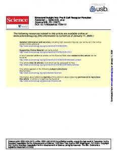
Figure29 shows the overall speedup for the four architectures, calculated by taking the geometric mean of the individual kernel speedups.
1.20
Name
Description
DCT
Discrete Cosine Transform: Transforms an 8x8 matrix of 16-bit fixed-point numbers.
FFT
Fast Fourier Transform: Performs a 1024-point floating-point FFT.
FFT-U4
FFT with the inner loop unrolled four times.
FIR-FP
Finite-Impulse-Response Filter: 56-tap floatingpoint FIR filter.
FIR-INT
FIR with 16-bit integer coefficients and data.
Block Warp
Performs a 3-D perspective transformation used for point-sample rendering [8].
Block Warp-U2
Block Warp with the inner loop unrolled twice.
Triangle Transform
Performs a 3-D perspective transformation on a stream of triangles.
Sort
Sorts 32 elements into an ordered set.
Merge
Merges two streams of sorted elements into a single sorted stream.
Since kernel performance is dominated by the loop, speedup was calculated as the inverse of the schedule length of that loop normalized to the schedule length for the central register file architecture. Figure28 shows the speedup for each kernel on each of the four register file architectures.
FFT-U4 DCT FIR-FP Sort
FFT Merge FIR-INT
Triangle Transform Block Warp-U2 Block Warp
1.00
Kernel Speedup
1.00
0.80
0.60
0.40
0.20
0.00
Central
Clustered (2)
Clustered (4)
Distributed
1.00
0.82
0.82
0.98
Register File Architecture
FIGURE 29. Overall Speedup vs. Register File Architecture These results demonstrate that communication scheduling enables effective scheduling to an architecture in which each functional unit input or output can be connected to multiple register files using shared buses and register file ports. In evaluating these results, it is important to distinguish between the target architecture, the scheduling algorithm, and communication scheduling. The target architecture places an upper bound on performance, reachable with optimal scheduling. This upper bound is determined by the mix of functional units, the number of cycles a functional unit requires to perform an operation, and the limitations of the register file topology. Since this paper evaluates communication scheduling and not register file architectures, the mix of functional units and operation latency (including register file access time) is the same for all architectures. In reality, a multiple register file architecture could support many more functional units with the same area and power. Further, due to lower register file access time, a multiple register file architecture would offer lower operation latency than a central register file architecture. The results given in this paper do not include these advantages. Thus, the upper bound on performance for any multiple register file architecture is equal to or lower than the upper bound for performance on a central register file architecture. The upper bound for each multiple register file architecture depends on limitations of the register file topology. The scheduling algorithm alone determines how close this architectural upper bound is approached on a central register file architecture. Communication scheduling is irrelevant for a central register file architecture, so much of the influence of the scheduling algorithm is factored out by normalizing the result for the scheduling algorithm with communication scheduling on a multiple register file architecture to performance of the same scheduling algorithm on a central register file architecture.
1.20
0.80
0.60
0.40
0.20
0.00
Central
Overall Speedup
TABLE 1. Evaluation kernels
Clustered (2)
Clustered (4)
Distributed
Register File Architecture
FIGURE 28. Kernel Speedup vs. Register File Architecture
Previous scheduling algorithms have incorporated support for clustered register file architectures. However, each standard functional unit in a clustered register file architecture can only read from and write to its own cluster register file. Thus, any intercluster communication requires a copy operation. The results show that these copy operations impact performance. The overall speedup for both clustered architectures is 0.82. Almost all kernels experience some performance degradation, and the minimum speedup is 0.56.
Communication scheduling works for architectures in which each functional unit can read from or write to multiple register files using shared interconnect, such as a distributed register file architecture. The results show that a scheduler with communication scheduling applied to a distributed register file architecture yields performance that is comparable to a single register file architecture. The overall speedup for a distributed register file architecture is 0.98. Seven out of the ten kernels evaluated have the same performance on a distributed register file architecture as on a central register file architecture, and the minimum kernel speedup is 0.91.
use an estimate of the number of registers implicitly allocated in each register file to influence routing decisions.
Communication scheduling does not require backtracking to schedule any of the evaluation kernels on the distributed register file architecture, demonstrating the infrequency of the special case described in Section4.5.
8. CONCLUSIONS
6. RELATED WORK Previous scheduling algorithms have concentrated on scheduling operations on cycles and assigning them to functional units (or clusters). Most scheduling algorithms assign operations to functional units and schedule operations on cycles using separate phases [1][4][6][10][12]. Usually, each operation is first assigned to a functional unit. Operations are then assigned to cycles using a top-down or bottom-up traversal of an acyclic version of the data dependency graph. The earliest cycle each operation can be issued on is the cycle after the last operation it is dependent on completes. However, the multi-phase approach requires that an operation be delayed to a later cycle if an assigned functional unit is occupied, even if another suitable functional unit is available. Unified Assign and Schedule (UAS) [13] assigns operations to functional units and cycles in a single phase. UAS attempts to assign each operation to the earliest possible cycle. If any functional unit that can perform the operation is available on that cycle, UAS provisionally assigns the operation to that functional unit then tries to schedule copy operations. UAS only delays an operation to a later cycle if it is unable to schedule copy operations for all available functional units. Some scheduling algorithms target specific architectures that take incremental steps beyond a clustered register file architecture. Distributed modulo scheduling [7], another single-phase scheduling algorithm, targets a clustered register file architecture that places special communication queue register files between clusters (“distributed” does not refer to a distributed register file architecture). The polycyclic compiler [14] targets an architecture that allows functional units to read from/write to multiple register files, but provides a dedicated register file between every functional unit output and every functional unit input to avoid resource conflicts. The Cydra5 compiler [3] targets an architecture in which each functional unit input can read from multiple register files, but provides each input with a dedicated bus and a dedicated register file port to access each register file. The TMS320C6x compiler [17] targets an architecture with two cluster register files that includes a small number of cross-cluster buses, but it still provides each functional unit input and output with a dedicated bus and register file port to access its cluster register file to guarantee a conflict-free way to read operands and write results.
7. FUTURE WORK The implementation of communication scheduling described in this paper does not consider register allocation. When communication scheduling assigns a communication to a route through a specific register file, it implicitly allocates a register in that register file. Register file overflows can be handled with a post pass that inserts additional copy operations to “spill” values into other register files by copying each value out of the overflowing register file just after it is computed and copying it back in just before use. However, an improved form of communication scheduling would
Communication scheduling supports a very large range of register file architectures, and additional work outside of the scope of this paper is needed to evaluate those architectures. This paper presents a specific distributed register file architecture that demonstrates the effectiveness of communication scheduling, but other architectures may yield even better results.
Communication scheduling enables scheduling to architectures in which functional units are connected to multiple register files by shared buses and register file ports. Scheduling to these shared interconnect architectures is difficult because it requires simultaneously allocating functional units to operations and buses and register file ports to the communications between operations. Communication scheduling solves this problem by making each communication explicit and incrementally composing it from three components: a write stub, zero or more copy operations, and a read stub. When the first operation is scheduled, the first stub is tentatively allocated. When the second operation is scheduled, both stubs are allocated and any required copy operations are scheduled. This composition allows the communicating operations to be scheduled independently while ensuring that the interconnect resources will be available to complete the communication. Communication scheduling is a general technique that can be implemented as part of a variety of scheduling algorithms and applied to a large class of shared of architectures. Communication scheduling can be added to a scheduler simply by allowing communication scheduling to accept or reject each operation placement. Communication scheduling is not architecture specific. It can be used to explore novel register files architectures without implementing a custom compiler for each architecture. Shared interconnect architectures are required to efficiently support the ever-increasing number of functional units demanded by media processing applications. Communication scheduling allows media processing kernels to achieve 98% of the performance they would get with a central register file on a distributed register file architecture that requires only 9% of the area, consumes 6% of the power, and has 37% of the access delay. Clustered register file architectures are a partial solution for smaller numbers of functional units, but distributed register file architectures offer much greater benefits as the number of functional units increases. For the architecture with twelve functional units presented in this paper, a distributed register file architecture requires 56% as much area and 50% as much power as a clustered register file architecture with four clusters. For an architecture with forty-eight functional units, a distributed register file architecture would require 12% as much area and 9% as much power as a clustered register file architecture with four clusters.
Acknowledgements The research described in this paper was supported in part by the Defense Advanced Research Projects Agency under ARPA order E254 and monitored by the Army Intelligence Center under contract DABT63-96-C-0037, and in part by Intel Corporation and Texas Instruments Corporation. Several of the authors are also supported by National Science Foundation and/or Stanford Graduate Fellowships. The authors wish to thank the Imagine team and the many people who helped with this paper.
References: [1]
Capitanio, A., Dutt, N., and Nicolau, A. "Partitioned register files for VLIWs: A preliminary analysis of trade-offs." Proceedings of the 25th Annual International Symposium on Microarchitecture, Dec., 1992, pp. 292-300.
[2]
Colwell, R., Hall, W., Joshi, C., Papworth, D., Rodman, P., and Tornes, J. "Architecture and implementation of a VLIW supercomputer." Proceedings in Supercomputing, Nov., 1990, pp. 910-919.
[3]
Dehnert, J. and Towle, R. "Compiling for the Cydra 5." Journal of Supercomputing, Jan., 1993, 182-227.
[4]
Desoli, G. “Instruction assignment for clustered VLIW DSP compilers: A new approach.” Technical Report HPL98-13, Hewlett-Packard Laboratories, Feb., 1998.
[5]
Diefendorff, K. and Dubey, P. “How multimedia workloads will change processor design.” Computer, Sept., 1997, pp. 43-45.
[6]
Ellis, J., Bulldog: A compiler for VLIW architectures. Cambridge, MA: MIT Press, 1986.
[7]
Fernandes, M., Llosa, J., and Topham, N., "Distributed modulo scheduling." Proceedings of the 5th Annual International Conference on High Performance Computer Architecture, Jan., 1999, pp. 130-134.
[8]
Grossman, J. and Dally, W. "Point sample rendering." Proceedings of the 9th Eurographics Workshop on Rendering, June, 1998, pp. 181-192.
[9]
Lam, M. “Software pipelining: An effective scheduling technique for VLIW machines.” Proceedings of the Conference on Programming Language Design and Implementation, June, 1988, pp. 318-328.
[10]
Lowney, P., Freudenberger, S., Karzes, T., Lichtenstein, W., Nix, R., O’Donnell, J., and Ruttenberg, J. “The Multiflow trace scheduling compiler.” Journal of Supercomputing, Jan., 1993, pp. 51-142.
[11]
Mangione-Smith, W., Abraham, S., and Davidson, E. "Register requirements of pipelined processors." Proceedings of the International Conference on Supercomputing, July, 1992, pp. 260-271.
[12]
[13]
Nystrom, E., and Eichenberger, A. "Effective cluster assignment for modulo scheduling." Proceedings of the 31st Annual International Symposium on Microarchitecture, Dec., 1998, pp. 103 - 114. Ozer, E., Banerjia, S., and Conte, T. "Unified assign and schedule: A new approach to scheduling for clustered register file microarchitectures." Proceedings of the 31st Annual International Symposium on Microarchitecture, Dec., 1998, pp. 308-315.
[16]
Rixner, S., Dally, W. J., Kapasi, U. J., Khailany, B., LopezLagunas, A., Mattson, P., and Owens, J. D. "A bandwidthefficient architecture for media processing", Proceedings of the 31st Annual International Symposium on Microarchitecture, Dec., 1998, pp. 3-13.
[17]
Stotzer, E. and Leiss, E., “Modulo scheduling for the TMS320C6x VLIW DSP architecture,” Proceedings of the ACM SIGPLAN 1999 Workshop on Languages, Compilers, and Tools for Embedded Systems, May, 1999, pp. 28-34.
Appendix A: Copy-connected architectures Communication scheduling works for all multiple register file architectures that are copy-connected. In a copy-connected architecture, if the result of one operation is to be used as an operand of another operation, either operation can be assigned independently to any functional unit that can perform that operation. As long as the result is written into one of a set of register files specific to the reading operation and operand, zero or more copy operations can be used to move the value to a register file from which it can be read as an operand. More formally, an architecture is copy-connected if: For any pair of operations, o1 and o2, and a specific operand of o2, operand, such that the result of o1 can be used as operand of o2, it is possible to find two sets of register files as a function of o2 and operand, RFwrite(o2, operand) and RFread(o2, operand), such that:
•
The output of any functional unit that can perform o1 is connected to at least one register file in RFwrite
•
Every input that can be used to read operand by any functional unit that can perform o2 is connected to at least one register file in RFread
•
Zero or more copy operations can be used to move a value from any register file in RFwrite to any register file in RFread Figure30 graphically depicts this constraint.
functional units that can perform o1
register files in RFwrite (zero or more copy operations to move value from one register file to other)
register files in RFread
functional units that can perform o2
[14]
[15]
Rau, B., Glaeser, C., and Picard, R., “Efficient code generation for horizontal architectures: Compiler techniques and architectural support." Proceedings of the International Symposium on Computer Architecture, July, 1982, pp. 131139. Rixner, S., Dally, W. J., Khailany, B., Mattson, P., Kapasi, U. J., and Owens, J. D. "Register organization for media processing", 6th International Symposium on High-Performance Computer Architecture, Jan., 2000, pp. 375-386.
FIGURE 30. Graphical depiction of copy-connected architecture constraint