Compact and Efficient Encryption/Decryption Module for FPGA ...
Recommend Documents
(1984) 144â146. 2. Feldmeier, D.C. A high speed crypt program (1989) Technical Memo TM-ARH- ... C. John Wiley & Sons, New York (1996). 20. Menezes, A.
Compared with custom- design, modular ... technologies, both in hardware and software, has been .... Each method has its own advantages: the customized.
balancing [2]. The available digital control hardware options include ... architecture of the DC-DC converter system, including the DC-DC ..... Step-Down. 2.1. 1.8.
With the Knowledge of VLSI, we can implement a Project in the field of Voice and Data Communication networks, Digital Signal Processing, Automobiles, Commercial Electronics, and Medical Electronics.
AbstractâWe propose a novel end-to-end framework to customize execution ... based realizations of neural networks is often bounded by the memory access ... a novel end-to-end framework to customize execution of deep neural networks ...... âCompre
School of Engineering, University of Warwick, United Kingdom. â . School of Engineering ... a noticeable proportion of the world's energy budget. One strategy ..... 8GB of on-board memory. It is hosted in an HP ... into a shift register. When a non
level) routing and then we run internal (intra-cluster) rout- ing. With such an approach we aim at reducing the external interconnect (Mesh level) while keeping a ...
way to integrate accelerators in the cloud, since they can be reprogrammed as needs ... Cloud Computing promises shared elastic access to unlim- ited compute ...
20-7 Kiyohara Kogyo Danchi, Utsunomiya, Tochigi, Japan. E-mail address: [email protected]. Abstract: We fabricated an opto-electronic transceiver module ...
custom integrated circuit that can have software downloaded to program it for specific .... They consume more resources than the CIC but this allows tailoring the ...
Jun 28, 2008 - System Generator is a DSP design tool from Xilinx that enables the use of The. MathWorks model-based design environment, Simulink for ...
This paper presents our conceptual design for laser drivers used in Laser Inertial Fusion Energy (LIFE) power plants. Although we have used only modest.
Dec 1, 2004 - The grating is only 13 mm long and 12 mm wide, and the size of the grooves is optimized ... below 1 dB using an inverted lateral taper with a poly- mer overlay. Although this is a good solution to the ... Letter angle u will be 8±.
Dec 4, 2017 - SnowFlake provides a computational efficiency of 91%, and an operating frequency of 250 MHz (best-in class for CNN accelerators on Xilinx.
Power-Efficient Computation Based on Difference Schemes. Kentaro Sanoâ ... governing equations of physics, which are approximated by ap- plying the ...
Introduction. Magnetic Induction Tomography (MIT) is a contactless and non-invasive method to obtain cross-sectional images of the conductivity, permittivity ...
IJCSNS International Journal of Computer Science and Network Security, VOL.9 No.12, December 2009. 16. Manuscript received December 5, 2009.
novel processor architecture is based on a custom datapath that exploits the ... that the implementation of the security services in the mobile applications com-.
the art in compiling high-level programs to FPGAs, and to survey the relevant research work ... flexibility of general-purpose processors and the hardware- based speed of ... but its advantage is that the learning curve is much lower than other desig
stead of former parallel forms of data transmission due to .... recovery (CDR) was used. Digital data .... appear mainly in form of individual corrupted bits caused.
Mar 23, 2008 - work shows that there is actually a large hardware design space of Spiking Neural. Network ...... We will call the time needed to simulate a single ..... 159, German National Research Center for Information Technology (2002).
Oct 13, 2014 - bits to store a prefix code with average codeword length within an ... An instantaneous code assigns a binary code ci to each symbol ai so that.
Efficient, Compact, and Dominant Color Correlogram Descriptors for. Content-based Image Retrieval. Ahmed Talib, Massudi Mahmuddin, Husniza Husni.
Compact and Efficient Encryption/Decryption Module for FPGA ...
Compact and Efficient Encryption/Decryption Module for. FPGA Implementation of the AES Rijndael. Very Well Suited for Small Embedded Applications.
Compact and Efficient Encryption/Decryption Module for FPGA Implementation of the AES Rijndael Very Well Suited for Small Embedded Applications Ga¨el Rouvroy, Franc¸ois-Xavier Standaert, Jean-Jacques Quisquater and Jean-Didier Legat UCL Crypto Group Laboratoire de Micro´electronique Universit´e catholique de Louvain Place du Levant, 3, B-1348 Louvain-la-Neuve, Belgium rouvroy,standaert,quisquater,[email protected] Abstract
systems.
1. Introduction
Hardware implementations of the Advanced Encryption Standard (AES) Rijndael algorithm have recently been the object of an intensive evaluation. Several papers describe efficient architectures for ASICs1 and FPGAs2 . In this context, the highest effort was devoted to high throughput (up to 20 Gbps) encryptiononly designs, fewer works studied low area encryptiononly architectures and only a few papers have investigated low area encryption/decryption structures. However, in practice, only a few applications need throughput up to 20 Gbps while flexible and low cost encryption/decryption solutions are needed to protect sensible data, especially for embedded hardware applications. This paper proposes an efficient solution to combine Rijndael encryption and decryption in one FPGA design, with a strong focus on low area constraints. The proposed design fits into the smallest Xilinx FPGAs3 , deals with data streams of 208 Mbps, uses 163 slices and 3 RAM blocks and improves by 68% the best-known similar designs in terms of ratio T hroughput/Area. We also propose implementations in other FPGA Families (Xilinx Virtex-II) and comparisons with similar DES, triple-DES and AES implementations.
In October 2000, NIST (National Institute of Standards and Technology) selected Rijndael [4] as the new Advanced Encryption Standard (AES), in order to replace the old Data Encryption Standard (DES). The selection process included performance evaluation on both software and hardware platforms and many hardware architectures were proposed. However, most of these architectures simply transcript the algorithm into hardware designs, without relevant optimizations and tradeoffs. Moreover, the throughput and area constraints considered are often unrealistic as shown by the recently published results. First, many very high-speed (≥ 10 Gbps) cipher hardware implementations have been published in the literature. These designs consists of FPGA implementations of a complete unrolled and pipelined cipher. The best such DES implementation is an encryptor/decryptor based on a new mathematical description. It can achieve data rates of 21.3 Gbps in Virtex-II FPGAs [15]. The encryption/decryption mode can be changed on a cycle-by-cycle basis with no dead cycles. For the AES, the best similar RAM-based solution unrolls the 10 cipher rounds and pipelines them in an encryption-only process. This implementation in a Virtex-E FPGA produces a throughput of 11.8 Gbps [17, 18] and allows the key to be changed at every cycle. This DES implementation reaches higher throughput than the corresponding AES implementation.
Application Specific Integrated Circuit. Field Programmable Gate Array. 3 Xilinx Spartan-3 XC3S50.
2 FPGA:
1
However, these speed efficient designs are not always relevant solutions. Many applications require smaller throughput (wireless communication, digital cinema, pay TV, ...). Sequential designs based on a 1round loop may be judicious and attractive in terms of hardware cost for many embedded applications. Several such implementations have been published in the literature. For DES and triple-DES designs, the most efficient solution [16] encrypts/decrypts in 18 cycles with a fresh key. For AES, the best design based on 1-round loop [17, 18] produces a data rate of 1450 Mbps (Virtex-E) using 542 slices and 10 RAM blocks, but it does not support the decryption mode. Another efficient circuit [20] proposes a compact architecture that combines encryption and decryption. It executes 1 round in four cycles and produces a throughput of 166 Mbps (Spartan-II) using 222 slices and 3 RAM blocks. The design proposed in this paper is also based on a quarter of round loop implementation and improves by 68% (in term of ratio T hroughput/Area) the design detailed in [20]. We investigate a good combination of encryption/decryption and place a strong focus on a very low area constraints. The resulting design fits in the smallest Xilinx devices (e.g. the Spartan3 XC3S50 and Virtex-II XC2V40), achieves a data stream of 208 Mbps (using 163 slices, 3 RAM blocks) and 358 Mbps (using 146 slices, 3 RAM blocks), respectively in Spartan-3 and Virtex-II devices. It attempts to create a bridge between throughput and cost requirements for embedded applications. The paper is organized as follows: section 2 describes the smallest Spartan-3 and Virtex-II devices; the mathematical description of Rijndael is in section 3; section 4 describes our sequential AES encryptor/decryptor; finally, section 5 concludes this paper.
a 4-input LUT, 16 bits of distributed SelectRAM memory, or a 16-bit variable-tap shift register element. The output from the function generator in each slice drives both the slice output and the D input of the storage element.
Figure 1. The Spartan-3 CLB.
Figure 2. The Spartan-3 slice.
2. Spartan-3 and CLB description: the XC3S50 component
A specific feature of the slice is the 16-bit shift register configuration. The write operation is synchronous with a clock input and an optional clock enable. A dynamic read access is performed through the 4-bit address bus. Spartan-3 devices also incorporate 18-Kbit RAM blocks. These ones complement the distributed SelectRAM resources provided by the CLBs. Each RAM block is an 18-Kbit true dual-port RAM with two independently clocked and independently controlled synchronous ports that access a common storage area. Both ports are functionally identical. Virtex-II devices exploit the same architecture as Spartan-3. The XC3S50 and XC2V40 components are, respectively, the smallest Spartan-3 and Virtex-II compo-
The Spartan-3 configurable logic blocks (CLBs) are organized in an array and are used to build combinatorial and synchronous logic designs. Each CLB element is tied to a switch matrix to access the general routing matrix, as shown in Figure 1. A CLB element includes 4 similar slices, with fast local feedback within the CLB. The four slices are split into two columns of two slices with two independent carry logic chains and one common shift chain. Each slice includes two 4-input function generators, carry logic, arithmetic logic gates, multiplexers and two storage elements. As shown in Figure 2, each 4-input function generator is programmable as 2
2. An affine transform over GF (2).
nents. Table 1 illustrates the logic resources available in both components. Component CLB array: row × col. Number of slices Number of flip-flops Number of LUTs Max dist. selectRAM or shift reg. (bits) Number of RAM blocks
XC3S50 16 × 12 768 1, 536 1, 536
XC2V40 8×8 256 512 512
24, 576 4
8, 192 4
The SubByte transformation applied to the State can be represented as follows: SB(Statei ) =
3. The AES algorithm
SB(di15 ) SB(di10 ) SB(di ) 5 SB(di0 )
SB(di3 ) SB(di2 ) SB(di1 ) SB(di0 )
SB(di11 ) SB(di6 ) SB(di1 ) SB(di12 )
SB(di7 ) SB(di2 ) SB(di13 ) SB(di8 )
SB(di3 ) SB(di14 ) SB(di9 ) SB(di4 )
The inverse Shif tRow operation (InvShif tRow (ISR)) is trivial. M ixColumn (M C) operates separately on every column of the State. A column is considered as a polynomial over GF (28 ) and multiplied modulo x4 +1 with the fixed polynomial c(x):
c(x) =0 030 x3 +0 010 x2 +0 010 x +0 020 As an illustration, the multiplication by 0 020 corresponds to a multiplication by two, modulo the irreductible polynomial m(x) = x8 + x4 + x3 + x + 1. This can be represented as a matrix multiplication:
represents the most significant byte of the where data block of the round i. The corresponding Statei is: i i i i di15
d7 di6 di5 di4
SB(di7 ) SB(di6 ) SB(di5 ) SB(di4 )
SR(SB(Statei )) =
The Advanced Encryption Standard (AES, Rijndael) algorithm is a symmetric block cipher that processes data block of 128, 192 and 256 bits using, respectively, keys of the same length. In this paper, only the 128 bit encryption version (AES-128) is considered. The 128-bit data block and key are considered as a byte array, respectively called State and RoundKey, with four rows and four columns. Let a 128-bit data block in the ith round be defined as:
d11 di10 di9 di8
SB(di11 ) SB(di10 ) SB(di9 ) SB(di8 )
The inverse transformation is defined InvSubByte (ISB). Shif tRow (SR) performs a cyclical left shift on the last three rows of the State. The second row is shifted of one byte, the third row is shifted of two bytes and the fourth row is shifted of three bytes. Thus, the Shif tRow transformation proceeds as follows:
Table 1. Resources available in XC3S50 and XC2V40.
AES-128 consists of ten rounds. One AES encryption round includes four transformations: SubByte, Shif tRow, M ixColumn and AddRoundKey. The first and last rounds differ from the other ones. Indeed there is an additional AddRoundKey transformation at the beginning of the first round and no M ixColumn transformation is performed in the last round. This is done to facilitate the decryption process. SubByte (SB) is a non-linear byte substitution. It operates with every byte of the State separately. The substitution box (S-box) is invertible and consists of two transformations:
To achieve the inverse operation (InvM ixColumn (IM C)), every column is transformed by multiplying it with a specific multiplication polynomial d(x), defined by c(x) ⊗ d(x) =0 010 d(x) =0 0B 0 x3 +0 0D0 x2 +0 090 x +0 0E 0 AddRoundKey (AK) performs an addition (bitwise XOR) of the Statei with the RoundKey i :
1. Multiplicative inverse in GF (28 ). The zero element is mapped to itself. 3
i R15 i R AK(Ri ) = 14 i R13 i R12 i i rk15 rk11 i i rk14 rk10 rki i rk 13 9 i rk12 rk8i
i R11 i R10 R9i R8i rk7i rk6i rk5i rk4i
R7i R6i R5i R4i rk3i rk2i rk1i rk0i
4.1. Implementation of ShiftRow and InvShiftRow operations
R3i R2i ⊕ R1i i R0
In our design, the way to access the Statei , for the first quarter of the round, is described in Figure 3. We read di15 ,di10 ,di5 ,di0 in parallel from the input memory, and execute SubByte, M ixColumn and AddRoundKey. Then we write rei+1 i+1 i+1 sults di+1 15 ,d14 ,d13 , d12 to a different output memory. The second, third, and fourth quarters of the round are managed in a similar manner, depending on Shif tRow.
The inverse operation (InvAddRoundKey (IAK)) is trivial. RoundKeys are calculated with the key schedule for every AddRoundKey transformation. In AES128, the original cipher key is the first RoundKey 0 (rk 0 ) used in the additional AddRoundKey at the beginning of the first round. RoundKey i , where 0 < i ≤ 10, is calculated from the previous RoundKey i−1 . Let p(j) (0 ≤ j ≤ 3) be the column j of the RoundKey i−1 and let w(j) be the column j of the RoundKey i . Then the new RoundKey i is calculated as follows: w(0) w(1) w(2)
The best FPGA solution to implement such simultaneous read and write memory accesses is proposed in [20]. The solution is based on a shift register design. As described above, all calculations from the AddRoundKey are written into adjacent locations of the output memory in consecutive cycles. i+1 i+1 i+1 We store first di+1 15 ,d14 ,d13 , d12 in parallel, then i+1 i+1 i+1 i+1 d11 ,d10 ,d9 , d8 in parallel, and so on. Therefore we can store the consecutive round results into shift registers (one shift register per row of the State, four shift registers for four rows). Xilinx FPGAs propose a very space efficient solution to achieve a 16-bit shift register with a dynamic variable access. Four slices can implement an 8-bit wide, 16-bit long shift register. The four dynamic variable accesses are used to read the input memory content at correct positions into the rows. Four 8-bit wide shift register are needed, which corresponds to 16 slices.
Rot is a function that takes a four byte input [a0; a1; a2; a3] and rotates them as [a1; a2; a3; a0]. The function Sub applies the substitution box (S-box) to four bytes. The round constant rconi contains values [(0 020 )i−1 ;0 000 ;0 000 ;0 000 ].
4. Our sequential AES implementations
di15 di14 di 13 di12
Some designs propose an implementation based on one complete round, and iteratively loop data through this round until the entire encryption or decryption is achieved. Only one Statei is processed in one cycle. These designs are suited for feedback and nonfeedback modes of operation. As mentioned in [20], the AES round offers various opportunities of parallelism. The round is composed of 16 S-boxes and four 32-bit M ixColumn operations, working on independent data. Only Shif tRow needs to deal with the entire 128-bit State. Based on this observation, we propose an implementation using four S-boxes and one M ixColumn in order to compact the design. This decreases the area by a factor of four but increases the time of one round to four cycles. In practice, only the time-space tradeoff is modified. A similar approach was proposed in [20].
Figure 3. Memory accesses involved in the first calculation step of the round i. The InvShif tRow operation can be done using the same shift registers modifying the way to access the input memory. 4
4.2. Implementation of SubByte/MixColumn and InvSubbyte/InvMixColumn
Compared to the paper [20], we propose a more efficient combination of SubByte and M ixColumn operations, i.e. we use less resources than separated block implementations. Our solution takes advantage of specific features of the new Xilinx devices and perfectly fits into the Spartan-3 or Virtex-II technologies4 . The Spartan-3 and Virtex-II FPGAs have both dedicated 18-Kbit dual-port RAM blocks5 , that can be used to store tables for the combination of SubByte and M ixColumn. As also mentioned in [4], the consecutive SubByte and M ixColumn operations on the first quarter of the round can be expressed as ei15..12 : 020 010 0 010 0 030
The combination of SubByte M ixColumn can be expressed as: i
0
e15 13
ei12
The size of one Ti table is 8 Kbits for encryption. The corresponding similar table for decryption also takes 8 Kbits (IT0 to IT3 ). It is therefore possible to achieve the complete SubByte/M ixColumn and InvSubByte/InvM icolumn operations using two dual-port 18-Kbit RAM blocks. The proposed solution significantly reduces the resources used in [20].
SB(di15 ) SB(di10 ) SB(di5 ) SB(di0 )
4.3. Encryption/Decryption design choices One of the inconveniences of AES comes from the fact that the AddRoundKey is executed after M ixColumn in the case of encryption and before InvM ixColumn in the case of decryption. Such encryption/decryption implementation will therefore require additional switching logic to select appropriate data paths, which can also affects the time performance. The paper [20] mentions this problem but chooses to design like that anyway. AES decryption algorithm nevertheless allows InvM ixColumn and AddRoundKey to be reordered if we perform an additional InvM ixColumn operation on most of the RoundKeys (except the first and the last RoundKeys). More details about such scheduling of operations can be found in [4, 5]. At first sight, InvM ixColumn could seem to require much more area than the switching logic. This is especially true if the InvM ixColumn of the round is narrowly combined with the InvSubByte in RAM blocks. Nevertheless, the subsection 4.4 proposes a solution using very few additional resources but some extra cycles to generate all inverse Roundkeys (InvRoundKeys). Figure 4 summarizes our design choices concerning the data path round.
is not the case with Spartan-II. Spartan-II has dedicated 4-Kbit dual-port RAM blocks.
5 The
5
CIPHER ENABLE_OUT
tion process takes 48 cycles to generate the complete InvRoundKeys. Due to InvRoundKey 0 and InvRoundKey 10 , tables (T0 to T3 ) need to be changed. InvSubByte has to replace the duplicated SubByte. We define new 16Kbit tables (CT0 to CT3 ) combined with (IT0 to IT3 ). CT0 is illustrated below as an example: 0 0 0 0
The implementation of our AES key schedule is based on precomputing RoundKeys and InvRoundKey in advance and storing them in one RAM block. The difficult computation of the InvRoundkeys on-the-fly6 completely justifies this approach. Our implementation of the key schedule is shown in Figure 5. First, it computes 32-bits of all the RoundKey i per clock cycle. The results are stored in one dual-port block RAM, thanks to the first port. This step takes 44 clock cycles. In the same time, we also store SB(RoundKeys) data in the same RAM, but using the other port. It corresponds to the first step of the calculation process of InvRoundKeys. As mentioned in the subsection 4.3, InvRoundKey i equals to IM C(RoundKey 10−i ), except for the first InvRoundKey 0 and last InvRoundKey 10 , which equal to respectively RoundKey 10 and RoundKey 0 . If we need decryption processes, a second step has to be applied to SB(RoundKeys). Therefore, we start to calculate ISB(SB(RoundKey 10 )) and store it as InvRoundKey 0 . Then, we evaluate the result IM C(ISB(SB(RoundKey 10−i ))) which equals to IM C(RoundKey 10−i ) and we store it as InvRoundKey 1..9 . InvRoundKey 10 is generated as InvRoundKey 0 . This optional decryp6 It
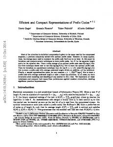
4.5. Implementation and results of our complete AES Our final AES design combines the data path part and the key schedule part. Since the key schedule is done with precomputation, this part does not work simultaneously with the encryption/decryption process. It is therefore possible to share resources between both circuits. Both parts of the circuit were thought to perfectly fuse together without additional slices7 and tristate buffers. This allows reaching higher frequency than in [20]. The global design is shown in Figure 6. We fused the key and plaintext inputs to one register. The input and output registers are packed into IOBs to improve the resources used and the global frequency of the design. 7 Only
Table 2. Comparisons with other sequential block cipher implementations.
Device
INPUTS PLAINT/KEY
CIPHER ENABLE_OUT
LUTs used Registers used Slices used RAM blocks Latency (cycles) Out. every (cycles) Frequency
32
32
Reset_IN 32
ROT
K_RAM
rconi
32
.......
SRL3
SRL16
XC3S50-4 293 126 163 3 46 1/44 71.5 MHz
XC2V40-6 288 113 146 3 46 1/44 123 MHz
.......
15
32 4X4
F5 32
2 RAM blocks
Table 3. Final results of our complete sequential AES.
Rd_ROW1 Rd_ROW2 Rd_ROW3 Rd_ROW4
MODE_DECR
CT0...CT 3 ISB
SB
of three internal RAM blocks. However, 3-DES remains interesting for applications that need to regularly change the key for encryption or decryption. Indeed, our AES design takes 92 cycles, in the worst case, to calculate a new complete InvRoundKeys.
32
ISB+IMC
F5
ADDRA ADDRB
DIA
DIB
1 RAM block RoundKey i or InvRoundKey i
32
K_RAM
Reset_K_RAM
5. Conclusion
Figure 6. Our complete AES design.
In this paper, we propose solutions for a very compact and effective FPGA implementation of the AES. We combine narrowly the non-linear S-boxes and the linear diffusion layer thanks to specific features of recent Xilinx devices. We also propose a low-cost solution to deal with the subkeys computed during the decryption step. In addition, we merge efficiently the key schedule and the data path parts. The resulting implementations fits in a very inexpensive Xilinx Spartan-3 XC3S50 FPGA, for which the cost starts below $10 per unit. This implementation can encrypt and decrypt a throughput up to 208 Mbps, using 163 slices. The design also fits in Xilinx Virtex-II XC2V40 and produces data streams up to 358 Mbps, using 146 slices. In comparison with 3DES, AES is more efficient if we do not care about the use of three internal FPGA RAM blocks. The throughput, low-cost and flexibility of our solution make it perfectly practical for cryptographic em-
The synthesis of our complete design was done using Synpllify Pro 7.2 from Synplicity. The place and route were done using Xilinx ISE 6.1.02i package. The final results are given in Table 3 for Spartan-3 and Virtex-II. As a comparison, we also set up a table with the previous AES [20], DES and 3-DES [16] results. Table 2 shows the results of these compact encryption/decryption circuits. Like others papers, we also define a ratio T hroughput/Area to facilitate comparisons. We finally achieve an implementation of AES which is 68% better in terms of T hroughput/Area assuming that Spartan-II and Spartan-3 are equivalent. In comparison with the most efficient compact 3DES circuits in XC2V40-6, we can conclude that AES is more effective if we do not care about the use 7
bedded applications.
[19] P. Chodowiec and K. Gaj. Comparison of the Hardware Performance of the AES Candidates using Reconfigurable Hardware. The Third Advanced Encryption Standard (AES3) Candidate Conference, April 13-14 2000, New York, USA.
References
[20] K. Gaj and P. Chodowiec. Very Compact FPGA Implementation of the AES Algorithm. In the proceedings of CHES 2003, Lecture Notes in Computer Science, vol 2779, pp. 319-333, Springer-Verlag.
[1] J.M. Rabaey. Digital Integrated Circuits. Prentice Hall, 1996. [2] Xilinx. The Virtex-II field programmable gate arrays data sheet,available from http://www.xilinx.com.
[21] V. Fischer and M. Drutarovsky. Two Methods of RIJNDAEL Implementation in Reconfigurable Hardware. In the proceedings of CHES 2001: The Third International CHES Workshop, Lecture Notes In Computer Science, LNCS2162, pp 65-76, Springer-Verlag.
[3] National Bureau of Standards. FIPS PUB 46, The Data Encryption Standard. U.S. Departement of Commerce, Jan 1977.
[22] A. Rudra et al. Efficient RIJNDAEL Encryption Implementation with Composite Field Arithmetic. In the proceedings of CHES 2001: The Third International CHES Workshop, Lecture Notes In Computer Science, LNCS2162, pp 65-76, Springer-Verlag.
[4] J. Daemen and V. Rijmen. The Block Cipher RIJNDAEL, NIST’s AES home page, available from http://www.nist.gov/aes. [5] P.Baretto, V.Rijmen, The KHAZAD Legacy-Level Block Cipher, Submission to NESSIE project, available from http://www.cosic.esat.kuleuven.ac.be/nessie/
[23] M. McLoone and J.V. McCanny, High Performance Single Ship FPGA RIJNDAEL Algorithm Implementations. In the proceedings of CHES 2001: The Third International CHES Workshop, Lecture Notes In Computer Science, LNCS2162, pp 65-76, Springer-Verlag.
[6] S. Trimberger, R. Pang and A. Singh. A 12 Gbps DES encryptor/decryptor core in an FPGA. In Proc. of CHES’00, LNCS, pages 156–163. Springer, 2000.
[24] M. McLoone and J.V. McCanny, Single-Chip FPGA Implementation of the Advanced Encryption Standard Algorithm. In the proceedings of FPL 2002: The Field Programmable Logic Conference, Lecture Notes in Computer Science, LNCS 2147, p.152ff.
[7] Xilinx, V. Pasham and S. Trimberger. High-Speed DES and Triple DES Encryptor/Decryptor. available from http://www.xilinx.com/xapp/xapp270.pdf, Aug 2001.
[25] K.U. Jarvinen, M.T. Tommiska and J.O. Skytta A fully Pipelined Memoryless 17.8 Gbps AES-128 Encryptor. In the proceedings of FPGA 2003: Symposium on Field-Programmable Gate Arrays, pp. 207-215, ACM.
[8] Helion Technology. High Performance DES and Triple-DES Core for XILINX FPGA. available from http://www.heliontech.com. [9] CAST, Inc. Triple DES Encryption Core. http://www.cast-inc.com. [10] CAST, Inc. DES Encryption http://www.cast-inc.com.
Core.
[11] inSilicon. X 3 DES Triple DES Cryptoprocessor. http://www.insilicon.com. [12] inSilicon. X DES Cryptoprocessor. http://www.insilicon.com.
[26] N. Weaver and J. Wawrzynek. High Performance Compact AES Implementations in Xilinx FPGAs. available from http://www.cs.berkeley.edu/ nweaver/Rijndael..
available from available
from
available from available
from
[13] P. Chodowiec, K. Gaj, P. Bellows and B. Schott. Experimental Testing of the Gigabit IPSec-Compliant Implementations of RIJNDAEL and Triple DES Using SLAAC-1V FPGA Accelerator Board. In Proc. of ISC 2001: Information Security Workshop, LNCS 2200, pp.220-234, Springer-Verlag. [14] J.P. Kaps and C. Paar. Fast DES Implementations for FPGAs and Its Application to a Universal Key-Search Machine. In Proc. of SAC’98: Selected Areas in Cryptography,LNCS 1556, pp. 234-247, SpringerVerlag. [15] G. Rouvroy, FX. Standaert, JJ. Quisquater, JD. Legat. Efficient Uses of FPGA’s for Implementations of DES and its Experimental Linear Cryptanalysis. In IEEE Transactions on Computers, Special CHES Edition, pp. 473-482, April 2003. [16] G. Rouvroy, FX. Standaert, JJ. Quisquater, JD. Legat. Design Strategies and Modified Descriptions to Optimize Cipher FPGA Implementations: Fast and Compact Results for DES and TripleDES. In the proceedings of FPL 2003, Lecture Notes in Computer Science, vol 2778, pp. 181-193, Springer-Verlag. [17] FX. Standaert, G. Rouvoy, JJ. Quisquater, JD. Legat. A Methodology to Implement Block Ciphers in Reconfigurable Hardware and its Application to Fast and Compact AES Rijndael. In the proceedings of FPGA 2003, pp. 216-224, ACM. [18] FX. Standaert, G. Rouvoy, JJ. Quisquater, JD. Legat. Efficient Implementation of Rijndael Encryption in Reconfigurable Hardware: Improvements and Design Tradeoffs. In the proceedings of CHES 2003, Lecture Notes in Computer Science, vol 2779, pp. 334-350, SpringerVerlag.