IEEE MICROWAVE AND WIRELESS COMPONENTS LETTERS, VOL. 24, NO. 5, MAY 2014
327
Compact Filtering Crossover Using Stub-Loaded Ring Resonator Xiu Yin Zhang, Senior Member, IEEE, Qing-Yi Guo, Kai-Xu Wang, Bin-Jie Hu, and Hong Lin Zhang
Abstract—This letter presents a novel compact crossover with bandpass responses. It consists of a stub-loaded ring and coupling feeding structures. The equivalent circuit of each path between two diagonal ports is a filtering circuit. The stub-loaded ring acts as the resonator in both two paths and thus the size is miniaturized. Meandering feeding structures are utilized to realize transmission zeros to improve the selectivity. To verify the design concept, a compact filtering crossover working at 2 GHz is implemented and the simulated and measured results are presented. Index Terms—Crossover, feeding structure, filtering responses, ring resonator.
I. INTRODUCTION
T
HE CROSSOVER is one of the fundamental components in microwave integrated circuits and is useful in Butler matrix designs. The crossovers can be designed using multilayer configurations [1], [2] . However, they may not be convenient for certain integrated planar circuits where planar crossovers are preferred. Recently, a series of four-port planar crossover circuits have been developed. The crossover based on the doublering design in [3] is a typical example. To expand the bandwidth, a ring and two inner orthogonal sections connecting the diagonal ports are utilized [4]. Branch-line couplers can also be employed in crossover designs [5], [6] . In [7], a fully symmetrical microstrip crossover with single- and dual-band operation is presented. The dual-band ones can also be implemented using two or three branch-line couplers [8], [9] . For passive microwave components including crossovers, miniaturization is an important issue. Integrating two functions in one component is an effective method for size reduction. Recently, some integrated designs have been reported such as the filtering hybrid coupler [10] and filtering power divider [11]. However, there is no literature on filtering crossovers. In this letter, a novel compact crossover integrated with bandpass responses is presented with good isolation performance over a very wide frequency range. As shown in Fig. 1, the filtering crossover can be equivalent to a crossover plus two bandpass filters (BPF). The filtering crossover consists of a stubManuscript received October 14, 2013; revised December 27, 2013; accepted February 10, 2014. Date of publication March 12, 2014; date of current version May 06, 2014. This work was supported by the NSFC under Grant. 61271060 and U1035002, by Guangdong Natural Science Funds for Distinguished Young Scholar under Grant S2013050014593 and the Project of DEGP (2012KJCX0012). The authors are with the School of Electronic and Information Engineering, South China University of Technology, Guangzhou 510641, China (e-mail:
[email protected]). Color versions of one or more of the figures in this letter are available online at http://ieeexplore.ieee.org. Digital Object Identifier 10.1109/LMWC.2014.2309083
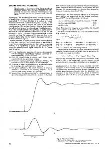
Fig. 1. Schematic of the crossover integrated with bandpass responses.
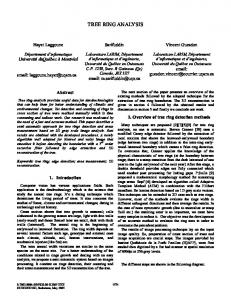
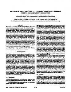
loaded ring and four coupling structures. The equivalent circuit of each path between two diagonal ports is equivalent to a filtering circuit and the ring is shared by the two filtering circuits as a common resonator. Thus, the size can be reduced. The resonant frequencies are theoretically derived and it is found they can be flexibly controlled. By introducing the meandering feeding lines and spur lines, four transmission zeros are generated on both sides of the passband, which can improve the selectivity. For validation, a filtering crossover is implemented. Measurement results are presented and agree well with the simulation data. II. ANALYSIS OF THE STUB-LOADED RING RESONATOR Fig. 2(a) shows the stub-loaded ring resonator. It consists of a ring and four identical open-ended stubs. If even-odd mode citation is applied to ports 3’ and 4’, the symmetrical plane in Fig. 2(a) becomes the perfect magnetic wall and electric wall, respectively. The resulting equivalent odd- and even-mode circuits are shown in Fig. 2(b) and (c). For the odd-mode circuit in Fig. 2(b), the ports 1’ and 2’ are short-circuited and this mode cannot be used. For the even-mode circuit in Fig. 2(c), it is still symmetrical and the even-odd mode analysis can be further utilized. Under the condition of , the two resonant frequencies can be derived as follows [12]: (1) (2) where is the light speed in free space, and denotes the effective dielectric constant of the substrate. For validation, the simulated and of the resonator under weak coupling with different is plotted in Fig. 3. As can be seen, at the frequency , the signals fed from port 1’ can be delivered to port 2’ but cannot be delivered to port 3’. This is because the port 3’ is shorted in the equivalent path of this mode. Therefore, it provides transmission to diagonal ports and isolation to adjacent ports. This mode is suitable for the crossover design.
1531-1309 © 2014 IEEE. Personal use is permitted, but republication/redistribution requires IEEE permission. See http://www.ieee.org/publications_standards/publications/rights/index.html for more information.
328
IEEE MICROWAVE AND WIRELESS COMPONENTS LETTERS, VOL. 24, NO. 5, MAY 2014
Fig. 4. Schematic of the feeding line.
Fig. 2. (a) Structure of the proposed resonator; (b) Odd-mode equivalent circuit; (c) Even-mode equivalent circuit. (d) Odd-mode equivalent circuit of Fig. 2(c). (e) Even-mode equivalent circuit of Fig. 2(c).
Fig. 5. Proposed filtering crossover.
Fig. 3. Simulated while against
and
of the resonator under weak coupling .
At the frequency , the signals fed from port 1’ can be delivered to both ports 2’ and 3’, as shown in Fig. 3. This mode will degrade the isolation performance between the two paths from the diagonal ports. Moreover, it will affect the selectivity because it is close to the operating frequency . To overcome the problems, the two frequencies and should be separated or the mode should be suppressed. The former one can be realized by tuning the length and , as indicated by (1)(2). The latter one can be realized by introducing a transmission zero at , which can be generated by the feeding line shown in Fig. 4. The input admittance can be expressed as (3) where , and denote the characteristic admittance and electrical lengths of the microstrip lines. If ( ), is zero. Thus, the signals cannot be fed into the structure and transmission zeros can be generated to suppress the mode .
III. CIRCUIT DESIGN Fig. 5 shows the proposed microstrip filtering crossover. The cross-shaped stubs are loaded to the ring and the feeding lines can be surrounded on either side of it. The feeding lines can generate a transmission zero at the frequency . To obtain sharp roll-off rate of the lower passband edge, a spur-line with the length of is introduced to create a transmission zero [12]. With this configuration, the circuits of the two transmission paths between two diagonal ports are the same and thus . It is noted that the number of spur lines in various transmission paths between adjacent ports is different. However, the spur line only affects the responses near the transmission zero. Thus, is similar to . The design procedure of the filtering crossover can be summarized as follows: We can determine and using (1) and (2) based on the . Among them, is the wanted operating frequency. In this design, the even mode is suppressed by generating a transmission zero. Then we can use (3) to calculate the electrical length of the feeding line so that a transmission zero can be generated at . The gap , can be determined by the required external quality factor of the filtering circuits between two diagonal ports. The next step is to add spur lines to create the transmission
ZHANG et al.: COMPACT FILTERING CROSSOVER USING STUB-LOADED RING RESONATOR
329
In the measured results, more than 40 dB rejection levels within the upper stopbands are observed. Four transmission zeros are located at 1.1, 1.7, 2.5, and 3.4 GHz. The transmission zero at 1.7 GHz is generated by the spur line. The other three ones are generated due to the feeding lines which fulfill the requirement ( ). Fig. 6(b) shows the simulated and measured result of and . They are nearly the same and below within a wide frequency range, featuring wide isolation bandwidth. Comparison with some prior work is carried out in terms of the 20 dB isolation bandwidth, transmission zeros (TZs), size, and filtering responses, as tabulated in Table I. The proposed crossover has wideband isolation performance and exhibits the extra filtering function. Moreover, the circuit size is comparable to other planar crossovers. It is noted that the filtering function of the crossover is enabled and the crossover is equivalent to a crossover plus two bandpass filters. Thus, the proposed circuit is compact as compared to the combination of a crossover and two filters. IV. CONCLUSION
Fig. 6. Simulated and measured results. (a)
and
. (b)
and
.
TABLE I COMPARISON OF VARIOUS PLANAR CROSSOVER
zeros in the lower stopband. Thus, the initial parameters can be obtained and then a fine tuning is performed. For demonstration, a compact filtering crossover is fabricated on the substrate with a relative dielectric constant of 3.38, a thickness of 0.81 mm and a loss tangent of 0.0027. The dimensions are as follows: , , , , , , , , , , , , , , , , , , . The overall size of the filter is , where represents the guided wavelength at the center frequency. The simulation is carried out using IE3D and the results are measured using the network analyzer Agilent E5071C. Fig. 6(a) shows the simulated and measured results of and . The passband frequency is located at 2.0 GHz, with the 3-dB fractional bandwidth of 9.5%. The measured insertion loss is 1.7 dB.
This letter has presented a novel compact filtering crossover using a stub-loaded ring resonator. The design principle of the circuit has been presented. The crossover achieves wide-band isolation performance and filtering responses. The stub-loaded ring is shared by the equivalent filtering circuits of two paths. Thus, the size is very compact as compared to a crossover plus two filters. With the dual functions, this circuit is useful in wireless applications. REFERENCES [1] A. Abbosh, S. Ibrahim, and M. Karim, “Ultra-wideband crossover using mcrostrip to coplanar waveguide transitions,” IEEE Microw. Wireless Compon. Lett., vol. 22, no. 10, pp. 500–502, Oct. 2012. [2] W. D. Liu, Z. J. Zhang, Z. H. Feng, and M. F. Iskander, “A Compact Wideband Microstrip Crossover,” IEEE Microw. Wireless Compon. Lett., vol. 22, no. 5, pp. 254–256, May 2012. [3] Y. Chen and S. –P. Yeo, “A symmetrical four-port microstrip coupler for crossover application,” IEEE Trans. Microw. Theory Tech., vol. 55, no. 11, pp. 2434–2438, Nov. 2007. [4] Y. C. Chiou, J. T. Kuo, and H. R. Lee, “Design of compact symmetric four-port crossover junction,” IEEE Microw. Wireless Compon. Lett., vol. 19, no. 9, pp. 545–547, Sep. 2009. [5] J. J. Yao, C. Lee, and S. Ping, “Microstrip branch-line couplers for crossover application,” IEEE Trans. Microw. Theory Tech., vol. 59, no. 1, pp. 87–92, Jan. 2011. [6] J. J. Yao, “Nonstandard hybrid and crossover design with branch-line structures,” IEEE Trans. Microw. Theory Tech., vol. 58, no. 12, pp. 3801–3808, Dec. 2010. [7] J. Shao, H. Ren, B. Arigong, C. Z. Li, and H. L. Zhang, “A fully symmetrical crossover and its dual-frequency application,” IEEE Trans. Microw. Theory Tech., vol. 60, no. 8, pp. 2410–2416, Aug. 2012. [8] Z. W. Lee and Y. H. Pang, “Compact planar dual-band crossover using two-section branch-line coupler,” Electron. Lett., vol. 48, no. 21, pp. 1348–1349, Oct. 2012. [9] F. L. Wong and K. K. M. Cheng, “A novel, planar, and compact crossover design for dual-band applications,” IEEE Trans. Microw. Theory Tech., vol. 59, no. 3, pp. 568–573, Mar. 2011. [10] L.-S. Wu, B. Xia, W.-Y. Yin, and J.-F. Mao, “Collaborative design of a new dual-bandpass 180 hybrid coupler,” IEEE Trans. Microw. Theory Tech., vol. 61, no. 3, pp. 1053–1066, Mar. 2013. [11] X. Y. Zhang, K.-X. Wang, and B.-J. Hu, “Compact filtering power divider with enhanced second-harmonic suppression,” IEEE Microw. Wireless Compon. Lett., vol. 23, no. 9, pp. 483–485, Sep. 2013. [12] X. Y. Zhang, J.-X. Chen, Q. Xue, and Li S.-M, “Dual-band bandpass filters using stub-loaded resonators,” IEEE Microw. Wireless Compon. Lett., vol. 17, no. 8, pp. 583–585, Aug. 2007.