Progress In Electromagnetics Research, Vol. 129, 345–363, 2012
COMPARATIVE EVALUATION ON POWER-SPEED DENSITY OF PORTABLE PERMANENT MAGNET GENERATORS FOR AGRICULTURAL APPLICATION M. Norhisam1, * , S. Ridzuan1 , R. N. Firdaus1 , C. V. Aravind1 , H. Wakiwaka2 , and M. Nirei3 1 Department
of Electrical and Electronics, Faculty of Engineering, Universiti Putra Malaysia, Serdang 43400, UPM, Malaysia 2 Faculty
of Engineering, Shinshu University, 4-17-1 Wakasato, Nagano 380-8553, Japan 3 Nagano
National College of Technology, 716 Tokuma, Nagano 3818550, Japan Abstract—The comparative evaluation based on the power speed density of several types of portable Permanent Magnet Generator (PMG) considered for agricultural applications is presented. These generators are purposely designed to be used in agriculture sectors and thereby it should be of lightweight, small in size and ease to use. Six different generator topologies are developed for investigation of such purposes. A number of design parameters are considered to analyze the performance characteristics for each type of developed PMG. Based on the power speed density factor that is used to describe better generator performance, the suitable PMG for the agricultural application is identified through a comprehensive evaluation. 1. INTRODUCTION Recently, the demand for standalone power sources is increasing, in particular such as in agriculture, tourism, construction, landscape decoration, sports and military service. The standalone application requires an electrical supply that depends on the requirement of batteries with its limited power capability and reduced life cycle as with heavy loads. Portable electro-mechanical equipment such as electrical cutter, electrical chopper, electrical grinder and electrical harvester for Received 1 May 2012, Accepted 12 June 2012, Scheduled 26 June 2012 * Corresponding author: Misron Norhisam (
[email protected]).
346
Norhisam et al.
agriculture are few to name. The generator developed and investigated is used for powering mechanical cutter in palm fruit harvesting that require to be portable. Therefore, a portable power supply with a small size and light-weight of Permanent Magnet Generator (PMG) is highly required. A small size portable diesel engine is used as a prime mover in this investigation. Various works have been carried out to analyze and model the characterization and performance of several types of PMG. Most of them usually focus on the design and optimization such as of the PMG for wind turbine application [1–4]. Some of them are determined for loss evaluation and design optimization for direct driven PMG using simulation [5]. Reference [6], presents the optimal design of stator interior PMG with minimized cogging torque for wind power application. In reference [7], a new type of permanent magnet micro-generators is introduced that is suitable for very low power applications such as hand phone, hand watch, and PDA. Most of the papers above only focus on modeling and optimization of its own structure of PMG. Some of them focus on micro-generators where the overall size of PMG determines whether it is intended for high or low power application. The development of PMG that intended to be used in agriculture application where it demand high power capability, small in size and ease of use is much limited in practical applications. In context to that, several topologies of PMG are designed and developed recently [8–18]. However, a perfect evaluation on the best possible of PMG for the desired application is to be investigated further. This paper describes the comparative studies on the power speed density of several types of portable permanent magnet generator for agriculture application that are developed. The nominal rotor speed for PMG is 3000 rpm based on the prime mover. Numerous design parameters are considered for analysis on the performance characteristics to derive the best model that was fabricated earlier [8–14]. The power speed density factor that is used to describe the generator performance suitable for the agricultural application is used as the evaluation parameter. A comprehensive analysis is performed and based on the power speed density factor the choice of PMG for the application of interests is proposed. Although the generators developed are for agricultural applications but this can also be used for small size portable commercial and industrial applications. 2. PORTABLE PERMANENT MAGNET GENERATORS 2.1. Constructional Features of Various PMG Most commonly used commercial permanent magnet generators are of single stator and double stator structure depending upon the torque
Progress In Electromagnetics Research, Vol. 129, 2012
347
and power density requirements. Further there are also slot type and slot-less type depending upon the shape of the permanent magnet structure used. Slot type refers to the stator that is made from ferromagnetic material that keeps the winding in place whereas, slotless type refers to the stator that is made from non-ferromagnetic material that keeps the winding in place [13]. Higher flux density in the air gap is achieved in slot type as the mechanical gap between the rotor and stator slot is small resulting in a higher magnitude of output voltage, but with the increased ripple in the output waveform. Meanwhile, slot-less type ensures a good sinusoidal waveform of output voltage smaller in magnitude with reduced ripple. The generator under investigations is designed as a portable unit that supplies stand alone electrical power used for agricultural application. The generator is designed for single phase operation thus the coil is connected in series to produce the variable AC voltage. The operating principle is based on the electromagnetic induction between the stator and the rotor, with the rotor enclosing the magnet. As the rotor rotates the revolving magnetic flux emulating from the magnet flows towards the slot at the stator. A voltage is induced by the winding coil at the slot due to the rate of flux changes that travels along the other stator core, return to the air gap and completes the flux path through the magnet placed at the other side. For all the generators under considerations the rotor and stator are made from magnetic material such as soft steel (SS400) and the shaft is made from non-ferromagnetic material (SUS403). The rare earth permanent magnets (NdFeB) are used as a permanent magnet. The different types of generators considered for the investigations are presented as below. Table 1 shows the structure of various types of developed PMG in this research. Table 2 shows simulation on the flux distribution of various types of PMG. Different variations on the use and shape of the magnet structure is investigated by other researchers [16–19]. 2.1.1. Single Stator Slot Type Permanent Magnet Generator Single Stator Slot Type Rectangular (SSRPM) permanent magnet generator consists of stator coil and stator teeth [11, 12] is shown in the Table 1. The rotor structure is embedded with the rectangular permanent magnets, the rotor core, and a shaft. This gives an advantage for the rotor to operate at high-speed application with spacing of the permanent magnets at the appropriate spacing. Also, the use of only one PM provides the required flux to interact with each pole on the stator side. The flux lines of permanent magnet in SSRPM flow directly to the stator pole as can be inferred from Table 2. There exists a smaller percentage of flux leakage between permanent
348
Norhisam et al.
magnet poles. The flux density in stator pole is as close to 2.0 T, but well below the saturation limit of 2.2 T. This means that the optimal consideration of stator pole Volume and coil space is achieved with this dimension. Table 1. Structure of various type of developed PMG in this research. stator
Slot
Slot-less
Single
Rectangular PM (SSRPM)
Symmetrically PM (SSLSPM)
Arc PM (DSAPM)
Single Pole PM (SPPM)
#
!
Double
Rectangular PM (DSRPM)
Multiple Pole PM (MPPM)
Progress In Electromagnetics Research, Vol. 129, 2012
349
Table 2. Flux distribution of various type of developed PMG. Slot
Slot-less
Rectangular PM (SSRPM)
Symmetrically PM (SSLSPM)
Stator
Single
Flux lines
Flux density
Arc PM (DSAPM)
Flux lines
Double
Flux density
Rectangular PM (DSRPM)
Flux lines
Flux density
Flux lines
Flux density
Single Pole PM (SPPM)
Flux lines
Flux density
Multiple Pole PM (MPPM)
Flux lines
Flux density
2.1.2. Single Stator Slot-less Permanent Magnet Generator The basic structure of Single Stator Slot-less Symmetrical (SSLSPM) permanent magnet generator comprises coils on the stator without the
350
Norhisam et al.
slot teeth as shown in Table 1 [7, 10, 13]. The coil is wound according to its shape and glued to the yoke. The rotor structure comprises permanent magnets, rotor core, and a shaft. The permanent magnets are of rectangular shape and are placed diametrically in V-shape pattern. This V-shape pattern gives advantage for PMG by providing additional flux density in the air gap even though the mechanical gap is bigger as can be inferred from Table 2. In this topology, the same pole polarity of permanent magnet is kept facing each other. 2.1.3. Double Stator Slot Type Permanent Magnet Generator Double Stator Slot type Arc Permanent Magnet (DSSAPM) as shown in Table 1, has two stators at the outer surface and a single rotor in the inner sides [9]. The arc type permanent magnets are embedded inside the rotor and are magnetized in the circumferential direction. The magnets are placed between the wedges of magnetic material of the pole pieces in the rotor. The stator and rotor are made from magnetic material and non-ferromagnetic material, respectively. The fluxes traverses along the stator core, return across the air gap and then enter the pole of the other permanent magnet. The advantage of the double stator topology is that it increases the output power of the PMG. The implementation of the double stator topology eliminates the flux linkage that increases the output of the PMG as shown in Table 2. The use of inner stator is to optimize the usage of the flux leakage problem that occurs in a single stator generator due to the radial flux direction. Normally, single stator topology produces flux leakage that occurs around the PM. Usually, the magnetic flux passes the air gap, encircles the stator windings and passes the air gap again and back to the rotor, thereby providing the magnet a flux linkage. Even though double stator topology is highly intricate to fabricate, they are finding more suitable applications due its better efficiency. Another double stator type called DSRPM that uses a rectangular type of magnets in the rotor. Similar to DSAPM, the magnet of DSRPM is magnetized in the circumferential direction and is magnets are surface-buried in the rotor. The advantage of using rectangular type of magnet is that it reduces of the size of the magnet and the reduction of the complexity on the rotor fabrication. 2.1.4. Double Stator Slot-less Type Permanent Magnet Generator Table 1 also shows constructed Double Stator Slot-less Single Pole PM (SSPM) [10] and the Double Stator Slot-less Type Multiple Pole Permanent Magnet (MPPM) [9]. In the SSPM type, the outer and inner stator is composed of only coils without the slot teeth. Each coil
Progress In Electromagnetics Research, Vol. 129, 2012
351
is wound according to its shape and glued on to their respective outer and inner stator. The advantage of using an arc permanent magnet is to achieve higher magnetic flux density by utilizing the maximum rotor size as shown in Table 2. However, in comparison with double stator slot type topology this SPPM use the slot-less stator topology that has large air gap, thus the existence of the leakage flux though unavoidable, but can only be minimized. With reference to the SPPM with the arc shape double stator, a Multiple Pole Type Permanent Magnet (MPPM) with rectangular shape is used for the same structure. The advantage of this structure is to reduce the weight and at the same time maintain the output power of PMG. Furthermore, by using rectangular shape PM, the fabrication is easier than arc shape PM. The other part of the generator is similar in structure with SPPM. 2.2. Power Generation Concepts in PMG The internally generated voltage in the generator is based on Faraday’s Law as in (1). Hence, the rotation of the rotor produces rotating magnetic field in the stator. Consequently, the voltage is induced by the winding coil at the air gap due to its rate of change of flux. The generated RMS voltage, EG by the generator for one pole is calculated as in (2). dφ dt = 4.44f N φ
Vemf = N EG
[V]
(1)
[V]
(2)
where Vemf is the induced voltage in [V], N the number of turns, φ the flux through each turns in [Wb], EG the RMS voltage in [V], and f the rotation frequency of the PMG in [Hz]. The generated voltage for a single stator is from the only coil winding at the air gap. However, for a double stator, the coil winding at the outer and inner air gap induces the voltage in the PMG. The maximum current, Ia of the generator when connected to a pure resistance load RL is derived as in (3). EG Ia = q (Ra + RL )2 + (2πf Lc )2
[A]
(3)
where Ra is the armature resistance of the coil winding in [Ω], RL the load resistance in [Ω], and Lc the inductance of the coil winding in [H]. According to this equation, it shows that the current flowing depends on the internal generated voltage and coil inductance. Figure 1 shows the basic electrical equivalent circuit of the generator that is connected to a pure load resistance RL . The
352
Norhisam et al.
Ra
jXs
Ia
Vemf Load
RL
Ea
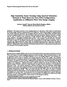
Figure 1. General electrical equivalent circuit. calculation to determine the performance of the generator is based on this circuit. Here, the value of RL is fixed for 95 Ω. This circuit is used as a reference in order to determine the performance of the generator by varying the Ra and Xs value. Here, Ia is the armature current in [A], and Xs is the synchronous reactance of the generator that composed of inductance of coil winding Lc and the armature effect in [Ω]. The machine losses considered includes the losses due to the armature reaction effect, the copper losses, and the iron losses. The general equation to calculate the armature reaction is given in Equation (4). The copper losses and iron losses that include the hysteresis and eddy current is calculated based on Equation (5). dIa Ea = Lc [V] (4) dt Pl = Ia2 Rc + εh f B α + εe f 2 B 2 [W] (5) where Ea is the armature voltage in [V], Pl the total losses power in [W], Rc the coil resistance in [Ω], εh the hysteresis coefficient (2.46 × 10⁻² ), εe the eddy current coefficient (8.55 × 10⁻³ ), α a constant (2.03), and B the flux density of the magnet in [T]. The total output power, Po that is generated by the generator is calculated based on Equation (6). For a single stator, the calculation is simple because it just has one voltage source. Po = (EG − Ea ) Ia − Pl [W] (6) However, for a double stator the calculation is separated between inner and outer voltage source as shown in Equation (7). This means that the calculation for a double stator is for the inner coil winding and outer coil winding. Subsequently, both output power is combined to obtain the total output power generated by the PMG in double stator strategy. Po = [(EGo − Eao ) Iao − Plo ] + [(EGi − Eai ) Iai − Pli ] [W] (7)
Progress In Electromagnetics Research, Vol. 129, 2012
353
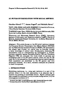
Figure 2. Experimental measurement setup used in this investigation. The input mechanical power that rotates the PMG is calculated using the value of torque as Equation (8). 2π × T × n [W] (8) 60 where Pm is the mechanical power of the machine in (W) that acts as a prime mover, T the torque value in (Nm), and n the rotational speed in (rpm). The value of torque is found through the measurement set-up as shown in Figure 2. The generator (denoted as PMG) is connected to a pure resistive load of 95 Ω. The voltage signal is measured between its terminals while the current is measured using a standard resistance of 1 Ω. The torque sensor is located between the PMG and DC motor that act as its prime mover. Finally, the efficiency, η is calculated as, Pm =
P0 × 100 [%] (9) Pm The torque is measured using the torque sensor and the mechanical power is calculated using Equation (8). The output power is calculated from Equation (6) or (7) depending upon the type as single and double slot topology respectively and the efficiency is calculated by Equation (9). η=
2.3. Characteristics of Various PMG Based on the concept presented in the previous section, a lot of design parameter is studied using Finite Element Method (FEM) and
354
Norhisam et al.
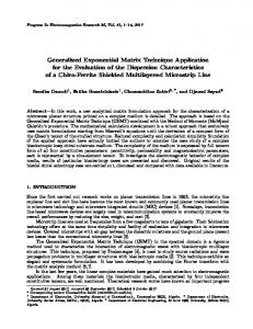
Permeance Analysis Method (PAM) [9–15]. The numerical method used for the analysis of the rectangular permanent magnet slot type of generator is presented in brief. The same method of permeance analysis is used for the analysis of other types of generators used in this invesitgations. Basically, the flux, Φ induced by the permanent magnet is calculated by using PAM. The direction of flux flow is considered based on the software analysis by using Finite Element Method (FEM). The permeance consideration area and its magnetic equivalent circuit are shown in Figure 3. As can be seen in Figure 3(b), there are two permeance areas at the air gap were considered including at the permanent magnet. The permanent magnet is considered as air gap in order to determine the total permeance for the coil. However, to examine the flux produced by the permanent magnet, the permeance at the permanent magnet, Pm is short circuit. P1 is the permeance area between stator teeth and rotor and can be calculated using Equation (10). The magnetic permeance is given by Equation (11). P1 =
µ lθ ³ o ´ ln 1 + rgr
Pm =
µwm l 2hm
[H] [H]
(a)
(10) (11)
(b)
P1
P1
Pm
Pm
(c)
Figure 3. Numerical computation for the rectangular slot type generator. (a) 2D flux direction (FEM). (b) Simplified flux path and permeance area in rectangular model. (c) Magnetic equivalent circuit.
Progress In Electromagnetics Research, Vol. 129, 2012
355
Here, µo is the permeability factor in the air in [H/m], µ the permeability of the material in [H/m], θ the angle of stator teeth in [rad], l the deep length of the PMG in [m], g the air gap between stator teeth and rotor in [m], rr the rotor radius in [m], wm the width of the permanent magnet slot in [m], and hm the height of the PM slot in [m]. Based on the magnetic equivalent circuit in Figure 4, the total permeance, Pt for one pole is calculated by using Equation (12) and calculated cumulatively as the other poles are identical. (µo µwm lθ) 1 ³ ³ ´´ Ptl = [H] (12) 2 (2µ h θ) + (µw ) ln 1 + g o m
m
rr
As mentioned before, the permeance at the magnet is short circuited in order to determine the flux at the magnet. Therefore, the total permeance in order to find the flux of the magnet is given by Ptf =
µ lθ ³o 2 ln 1 +
g rr
´
[H]
(13)
Assume the B-H curve of permanent magnet and permeance line of the PMG shown in Figure 4. The intersection point of these two lines is an operating point of the permanent magnet for the particular permeance model. By solving the intersection of these two straight lines, the permanent magnet operating point can be determined as in Equations (14) until (16).
B(T)
Demagnetization line of Permanent magnet
Br Permeance line
k Bk
αo
H(kA/m) Hc
Hk
Figure 4. B-H curve and operating point of permanent magnet.
356
Norhisam et al.
Ptf Hc hm Br wm l Bk = (− tan α) Hk −Br ´ Hk = ³ Br + tan α Hc
(14)
tan α =
[T] [A/m]
(15) (16)
Here, the operating point of permanent magHc is a coercive force in (kA/m), Br a remnant flux density in [T], Bk a magnetic flux density of the permanent magnet at operating point in [T], and Hk the magnetic field intensity of the permanent magnet at operating point in [A/m]. Consequently, the flux in the PMG can be calculated as: ¡ ¢ µo Br Hc2 hm θ ³ ´´ φ= ³ [Wb] (17) 2Br2 wm ln 1 + rgr + (Hc2 µo hm θ) The inductance Lc and resistance Rc of the coil winding are calculated by using Equations (18) and (19), respectively. These values are necessary in order to identify the characteristic of the PMG especially the maximum current in the circuit. Furthermore, the capability of the generator is limited by the impedance of the stator coil. N2 (µo µwm lθ) ³ ³ ´´ [H] (18) Lc = 2 (2µ h θ) + (µw ) ln 1 + g o m
Rc = N =
N 2 ρl A
c
=
wc hc × dc dc
m
2N 2 ρ (l
+ wy + wc ) wc hc
[Ω]
rr
[Ω]
(19) (20)
Here, N is the number of turns, lc the length of coil winding in [m], A the area of winding slot in [m2 ], ρ the density of copper [8900 kg/m3 ], wy the width of the stator yoke in [m], dc the diameter of the coil, wc the width of the coil slot in [m], and hc the height of the coil slot in [m]. From the initial study, analysis are carried to understand the performance and characteristics of each the generator structure. For each type of the generator, the best model based on the field analysis is chosen for fabrication and are tested experimentally. For all of the generators used here, the outer diameter of stator core and the diameter of the shaft is selected to be kept at 104 mm and 10 mm respectively. The thickness of stator core is fixed at 20 mm. Four different characteristics are evolved from the investigations
Progress In Electromagnetics Research, Vol. 129, 2012
357
namely, the torque-speed characteristic, the mechanical power-speed characteristic, the output power-speed characteristic and the efficiencyspeed characteristic. 2.3.1. Torque-speed Characteristics
Torque, T [Nm]
Mechanical Power, PM [W]
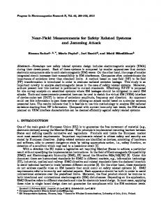
Figure 5(a) shows the torque-speed characteristic to drive the generator. It is inferred that the torque increases linearly and is proportional to the speed of the rotor. DSAPM requires the highest torque characteristic to move the rotor since it has the highest slope compared to the DSRPM, SSPM, MPPM and SSRPM. The low torque characteristic is shown by SSLSPM. It is inferred that the PMG with slot-less topology requires lower torque compared to the slot type. Meanwhile the double stator topology develops higher torque compared to the single stator. This is due to smaller air gap in the slot type that contributes to the higher cogging characteristic compared to slot-less type.
Speed, n [rpm]
Speed, n [rpm]
(b)
Efficiency, η [%]
Output Power, PO [W]
(a)
Speed, n [rpm]
Speed, n [rpm]
(c)
(d)
Figure 5. Characteristics of the various PMG that are fabricated. (a) Torque. (b) Mechanical power. (c) Output power. (d) Efficiency.
358
Norhisam et al.
2.3.2. Mechanical Speed-power Characteristics Figure 5(b) shows the mechanical power-speed characteristic of the prime mover of PMG’s. Similar to the torque characteristic, it is seen that the mechanical power increases as the speed of rotor increases. For instance, at 2000 rpm the output power for DSAPM is 280 W whereas the torque that required to move the rotor at that particular speed is about 1.25 Nm. Meanwhile, the mechanical power that required to produce the same amount of torque by the prime mover at the same speed is 250 W and the efficiency at that particular speed is about 84%. Again, DSAPM has the highest mechanical power characteristic to move the rotor since it has the highest torque compared to DSRPM, SSPM, MPPM and SSRPM. The lowest output power characteristic is shown by SSLSPM. 2.3.3. Output Power-speed Characteristics Figure 5(c) shows the output power vs speed characteristic for each PMG. This output power is determined using the calculation as presented in the previous section. For verification of the calculation, output power for each prototype is measured. However, only few of measurement results are shown in the graph. The calculated results are in good agreement with the measurement result. It is inferred that the output power increases almost proportional to the speed of the rotor. However, DSAPM has the highest output power characteristic since it has the highest slope compared to DSRPM, SSPM, MPPM and SSRPM. The lowest output power characteristic is shown by SSLSPM. DSAPM has the highest output power compared to DSRPM due to the bigger size of PM. Besides, a maximized and constant magnetic flux density along the surface of the arc is achieved due to the constant air gap between stator and rotor compared to DSRPM. Furthermore, it is inferred that the PMG with slot-less topology produce lower output power compared to the slot type. All these values of torque, mechanical power and the output power, the efficiency of all the PMG are then calculated. 2.3.4. Efficiency Characteristics Figure 5(d) illustrates the efficiency of all PMG that are fabricated. It is inferred that the efficiency of SSLSPM increases as the speed is increased until it reached the saturation point at speed 2000 rpm. For the other PMG, there are only small significant changes of the efficiency as the speed is increased. For example, among all PMG the DSAPM
Progress In Electromagnetics Research, Vol. 129, 2012
359
develops highest efficiency of 93% at 1500 rpm. Therefore, it shows that DSAPM is superior to other PMG under investigations. 3. COMPARISON OF VARIOUS PMG In order to evaluate the best suitability of the generator, the ratio of power density of the Volume of the generator is selected as the evaluating parameter. This main reason is that different kind of PMG generate different values of torque, mechanical power, output power and efficiency. Thus, by referring to power density, it shows the best possible PMG that produces the higher output power with the smallest of weight. The power-speed constant, Poc is calculated by finding the slope of output power when running at different speeds of PMG as shown in Figure 6. The Poc is calculated by Equation (21). y2 − y1 Poc = [W/rpm] (21) x2 − x1 The power speed density is then calculated using Equation (22) where the Poc is divided by Volume of the PMG. Pd = Poc /v
[W/rpm/m3 ]
(22)
Output Power, PO [W]
where v: the overall Volume of the PMG [m3 ]. Table 3 shows the comparison of various PMG prototypes that are fabricated based on the desired application. All the values here shown in the Table 3 are based on the measurement at 3000 rpm of the rotor speed. It is inferred that the highest output power is achieved by DSAPM (530 W) where as the lowest output power by SSRPM (194.88 W). The output power for SSLSPM, DSRPM, SPPM and MPPM are 62.26 W, 460 W, 261.8 W and 270.3 W, respectively.
Speed, n [rpm]
Figure 6. Method in determine the power-speed constant.
360
Norhisam et al.
Table 3. Comparitive evaluation of the various PMG prototypes that are fabricated (at 3000 rpm). Double
Single
Item Output Power, Po
[W]
Inductance, L [mH] Weight, m [kg] Volume, v
[m3]
Power Speed Constant, Poc [W/rpm] Power Speed Density , Pd [W/rpm/ m3] Resistance, R [Ω]
Slot
Slot-Less
Slot
SSRPM
SSLSPM
DSRPM
DSAPM
SPPM
Slot-Less
194.88
62.26
460
530
261.8
270.3
75.04
4.24
10.2
10.2
2.32
2.706
MPPM
1 .554
1.452
1.703
1.714
1.523
1.365
1.92 x 10⁻⁷
1.80 x 10⁻⁷
2.16 x 10⁻⁷
2.16 x 10⁻⁷
2.08 x 10⁻⁷
2.08 x 10⁻⁷
0.089 463.54 x 10 15.54
0.047 3
261.11 x 10 6.94
0.201 3
930.55 x 10 9.55
0.225 3
1041.67 x 10 9.55
0.174 3
836.54 x 10 4.05
0.179 3
860.58 x 10³ 4.05
This shows that for the same overall size and speed of generator, DSAPM is superior to other types generator presented. The value of inductance and resistance is higher for single stator especially slot-less type. This is because it encloses coil with bigger width in the stator rather that of the slot type. The highest inductance and resistance for the SSRPM type is 75.84 mH and 15.54 [Ω], respectively. The low inductance and resistance is for the SPPM, about 2.32 mH and 4.05 [Ω], respectively. It is inferred that low values of inductance and resistance contributes bigger output power of the generator. Furthermore, it is seen that the weight of generator is between 1.3 kg to 1.5 kg depending upon its type. The highest weight among the generator investigated is about 1.714 kg for the DSAPM and the smallest weight of 1.365 kg is for the MPPM topology as they use smaller permanent magnets and lower rotor weight. The highest power-speed constant of 0.225 W/rpm is achieved by DSAPM, as it exhibit higher slope of output power followed by DSRPM, MPPM, SPPM, SSRPM, and SSLSPM which are about 0.201 W/rpm, 0.179 W/rpm, 0.174 W/rpm, 0.089 W/rpm and 0.047 W/rpm, respectively. The power density of all the PMG is derived using the ratio of Poc to the overall volume. Based on Table 3, it shows that the highest power density of 1041.67 × 103 W/rpm/m3 achieved by DSAPM compared to other DSRPM (930.55 × 10³ W/rpm/m3 ), MPPM (860.58 × 10³ W/rpm/m3 ), SPPM (836.54 × 10³ W/rpm/m3 ), SSRPM (463.54 × 10³ W/rpm/m3 ) and SSLSPM (261.11 × 10³ W/rpm/m3 ). Based on the above analysis, PMG with DSAPM topology is proposed as the high power density portable PMG for agricultural application. They can however be extended for similar applications in commercial and industrial sectors.
Progress In Electromagnetics Research, Vol. 129, 2012
361
4. CONCLUSION The comparative evaluation of the various types of generator that are developed for a portable electrical generator for agricultural application is presented. The characteristic including the torque, the mechanical power, the output power and the efficiency is presented. In order to differentiate the performance and capability of the generator, the power density, the ratio of power speed constant to overall Volume of the PMG is used as a performance evaluation factor. It is concluded based on the investigations that the DSAPM with its highest power density is the best generator for the desired application of interest as it develops high output power for a smaller size. REFERENCES 1. Jian, L., G. Xu, Y. Gong, J. Song, J. Liang, and M. Chang, “Electromagnetic design and analysis of a novel magnetic-gearintegrated wind power generator using time-stepping finite element method,” Progress In Electromagnetics Research, Vol. 113, 351–367, 2011. 2. Lecointe, J.-P., B. Cassoret, and J.-F. Brudny “Distinction of toothing and saturation effects on magnetic noise of induction motors,” Progress In Electromagnetics Research, Vol. 112, 125– 137, 2011. 3. Hosseini, S. M., M. A. Mirsalim, and M. Mirzaei, “Design, prototyping and analysis of low cost axial flux coreless permanent magnet generator,” IEEE Transactions on Magnetics, Vol. 44, No. 1, 75–80, 2008. 4. Touati, S., R. Ibtiouen, O. Touhami, and A. Djerdir, “Experimental investigation and optimization of permanent magnet motor based on coupling boundary element method with permeances network,” Progress In Electromagnetics Research, Vol. 111, 71–90, 2011. 5. Mahmoudi, N. A. Rahim, and H. W. Ping “Axial-flux permanent-magnet motor design for electric vehicle direct drive using sizing equation and finite element analysis,” Progress In Electromagnetics Research, Vol. 122, 467–496, 2012. 6. Herrault, F., D. P. Arnold, I. Zana, P. Galle, and M. G. Allen, “High temperature operation of multi-watt, axial-flux, permanentmagnet micro-generators,” Sensors and Actuators A, Vol. 148, 299–305, 2008.
362
Norhisam et al.
7. Arnold, D. P., “Review of micro-scale magnetic power generation,” IEEE Transaction of Magnetics, Vol. 43, No. 12, 3940–3951, 2007. 8. Norhisam, M., M. Nirei, M. Norafiza, I. Aris, J. Abdul Razak, and H. Wakiwaka, “Comparison of single and multiple pole permanent magnets in a double stator slot-less permanent magnet generator,” Journal of the Magnetics Society of Japan, Vol. 34, No. 3, 407–410, 2010. 9. Norhisam, M., M. Nirei, M. Norafiza, C. Y. Sia, and H. Wakiwaka, “Basic characteristics of double stator slot-type permanent magnet generator”, Journal of the Magnetics Society of Japan, Vol. 34, No. 3, 385–388, 2010. 10. Norhisam, M., R. Suhairi, M. Norafiza, M. A. M. Radzi, I. Aris, M. Nirei, and H. Wakiwaka, “Comparison on performance of a single phase and three phase double stator type permanent magnet generator,” Proceedings of the 6th Asia Pacific Symposium on Applied Electromagnetics and Mechanics, 231–234, Jul. 2010. 11. Norhisam, M., R. Suhairi, M. Norafiza, M. A. M. Radzi, I. Aris, M. Nirei, and H. Wakiwaka, “Comparison on performance of a single phase and three phase double stator type permanent magnet generator,” Proceedings of the 6th Asia Pacific Symposium on Applied Electromagnetics and Mechanics, 231–234, Jul. 2010. 12. Norhisam, M., M. Norafiza, M. Shafiq, I. Aris, J. Abdul Razak, H. Wakiwaka, and M. Nirei, “Comparison on performance of two types permanent magnet generator,” Journal of the Japan Society of Electromagnetic and Mechanics, Vol. 17, 73–76, Supplement, 2009. 13. Norhisam, M., M. Norafiza, M. Shafiq, I. Aris, M. Nirei, H. Wakiwaka, and J. Abdul Razak, “Design and analysis of slot type embedded permanent magnet generator,” Journal of Industrial Technology, Vol. 18, No. 1, 1–14, 2009. 14. Norhisam, M., M. Norafiza, M. Syafiq, I. Aris, and J. Abdul Razak, “Design and analysis of a single phase slot-less permanent magnet generator,” Proceedings of the 2nd IEEE International Conference on Power and Energy, 1082–1085, Dec. 2009. 15. Schimelman, D., “Tiny pumps drive portable medical devices,” World Pumps, Vol. 2008, No. 503, 22–25, 2008. 16. Ravaud, R. and G. Lemarquand, “Comparison of the Coulombian and Amperian current models for calculating the magnetic field produced by radially magnetized arc-shaped permanent magnets,” Progress In Electromagnetics Research, Vol. 95, 309–327, 2009. 17. Zhao, W., M. Cheng, R. Cao, and J. Ji, “Experimental comparison of remedial single-channel operations for redundant flux-switching
Progress In Electromagnetics Research, Vol. 129, 2012
363
permanent-magnet motor drive,” Progress In Electromagnetics Research, Vol. 123, 189–204, 2012. 18. Mahmoudi, A., S. Kahourzade, N. A. Rahim, and H. W. Ping, “Improvement to performance of solid-rotor-ringed line-start axial-flux permanent-magnet motor,” Progress In Electromagnetics Research, Vol. 124, 383–404, 2012. 19. Ravaud, R., G. Lemarquand, V. Lemarquand, and C. Depollier, “The three exact components of the magnetic field created by a radially magnetized tile permanent magnet,” Progress In Electromagnetics Research, Vol. 88, 307–319, 2008.