Comparison of Boost Chopper and Active Buffer as Single to Three Phase Converter Yoshiya Ohnuma
Jun-ichi Itoh
Student Member, IEEE Nagaoka University of Technology 1603-1 Kamitomioka-machi Nagaoka City Niigata, Japan
[email protected]
Member, IEEE Nagaoka University of Technology 1603-1 Kamitomioka-machi Nagaoka City Niigata, Japan
[email protected] [5]. These circuits add the a few switching devises and energy buffer such as capacitor or reactor to the conventional boost chopper. Certainly, the voltage ripple in the DC part can be reduced by the control of the energy buffer even if the small something capacitor is used in DC part. However, the additional circuit for the power decupling causes increasing the power loss.
Abstract—This paper presents a comparison in terms of efficiency and volume between the single-to-three-phase power factor correction (PFC) converter. A conventional PFC circuit that consists of a boost chopper requires a large boost-up inductor and large smoothing capacitors to decouple the power ripple. The size and efficiency of the converter become a discussion issue recently. On the other hand, a single-to-threephase power converter using an active buffer has been proposed. The active buffer does not require a large inductor and large smoothing capacitors in the DC link part. These two types of converters are designed and simulated to calculate the losses. In addition, a prototype converter has been built and tested. The efficiency achieves 94.6% at 1.5-kW same as the calculated efficiency. Furthermore, the efficiency increases by 1.5% comparing to the conventional converter. In addition, the volume is decreased by approximately 0.7 times then the size of the conventional converter.
I.
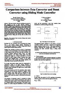
Apparently, a single-to-three-phase power converter with an active buffer (proposed converter) as shown in Fig. 2 has been proposed in [6] in terms of loss reduction of the power decoupling circuit. This converter is based on the concept of an indirect matrix converter that coupled with an active buffer to decouple the power ripple. The converter obtains sinusoidal waveforms on the input and output current. In addition, the size of the converter is reduced because the converter does not require a large smoothing capacitor and a large boost inductor in the DC link part. However, the clarifying of the efficiency and the volume are remained unidentified.
INTRODUCTION
Single-phase to three-phase converters achieve energy saving in the application of home motor appliances. One of the important requirements of the converter is to provide low input current harmonics. Therefore many power factor correction (PFC) converters and control methods have been proposed [1]-[3]. At the same time, studies on the high efficiency and design of the volume are very important subjects in this field. The most common structure of PFC converter is the single-switch boost chopper circuit (conventional converter) as shown in Fig. 1 [1]. This circuit can control the input current easily. However, this converter requires a large boost-up inductor and a large smoothing capacitor to decouple the power ripple, which is a frequency twice of the power supply at the DC link part. In addition, the DC link voltage is always higher than the maximum input voltage because a boost-up converter is used. Therefore the switching loss of this conventional converter becomes high.
This paper demonstrates a comparison on the efficiency and the volume among these converters. At first, the paper discusses the circuit layout and control methods for these single-to-three-phase PFC converters. There are two type of boost up operation modes which are known as the continuous current mode (CCM) and the discontinuous current mode (DCM). Second, each parameter of the passive components is designed and utilized in the simulation analysis in order to compare the losses of these converters.
In order to reduce the volume of the smoothing capacitor, some power decoupling converters have been proposed [4],
978-1-4577-0541-0/11/$26.00 ©2011 IEEE
Fig.1 Conventional converter.
515
Then the size of the heat sink is calculated based on the simulation results. Nevertheless, a prototype of the proposed converter has been built and tested in order to validate the loss analysis. As a result, the efficiency of the proposed converter is 1.5 % higher than the conventional converter with DCM boost chopper. In addition, the total volume of the passive components is approximately decreased by 0.7 times comparing to the conventional converter with CCM boost chopper. II.
Active buffer Dr1
Dr2
L Dp
•
The current of an inductor is either CCM or DCM.
•
Duty ratio of the switch in boost chopper is either constant or variable.
•
Frequency of the switch in boost chopper is either constant or variable.
M
SL
Dr4
Diode rectifier
CIRCUIT CHARACTERISTICS
Cdc
Charge Discharge circuit circuit
Inverter circuit
Fig.2 Proposed converter.
(a) Conventional converter with CCM
The simplest controls such as constant duty ratio, constant frequency or line frequency commutated control can obtain high power factor easily for low power applications. However, the input current remains distorted at low voltage boost ratio. On the other hand, advanced control strategies can control the input current into a clear sinusoidal waveform based on the duty ratio or switching frequency. In this paper, CCM or DCM operation with constant switching frequency and variable duty ratio methods are discussed.
(b) Conventional converter with DCM
(c) Proposed method
Figure 2 shows a single-to-three-phase converter with an active buffer [6]. The active buffer that consists of a discharge circuit and a charge circuit replaces the boost chopper to decouple the power ripple, which the power ripple has a frequency that is twice of the power supply. The discharge circuit consists of a small capacitor and a switch. The charge circuit is similarly to a boost chopper circuit but using a smaller inductance value because the current is controlled based on DCM. The voltage ripple in the DC link part is absorbed to the small capacitor Cdc by controlling its terminal voltage. The terminal voltage of Cdc has large fluctuation according to the energy ripple which comes from the input side.
Fig.3 three different control method diagrams for PFC circuits.
current command and switching period of the switch in boost chopper, respectively. Therefore, for both the conventional converters, the inductor current command il* is obtained by a PI controller. In the proposed control method, the power ripple is compensated by the discharge circuit and the charge circuit. The control method of the charge circuit is based on the DCM. Therefore the duty ratio is determined by (1). It should be note that the charge circuit and the discharge circuit are operating alternately at per quarter cycle of the power grid frequency. Thus, half of the input power is supplied directly to the inverter. Therefore the inductor current command il* is calculated by
Figure 3 shows three different control method diagrams for PFC circuits. The switching duty ratio dl of CCM is obtained by PI controller using the inductor current as shown figure 3 (a). In contrast, DCM can obtain the duty dl using the equation without a current sensor as follows:
*
*
il = I IN sin(ωt ) −
*
2 Lb (vc − vin )il , vin vc Tsw
SC
Input filter Lin Cin
Figure 1 shows a single-to-three-phase converter with a single switch boost converter. The converter consists of a diode rectifier, inverter and boost chopper. There are many control methods can be applied into this PFC [1]-[3]. The point of the control method is as following.
dl =
Dr3
(1)
I IN , 2 sin(ωt )
(2)
where IIN* is the amplitude of the input current command and ω is the input single phase angular frequency In addition, the capacitor voltage is fluctuating in this system. Hence, the power ripple WC which is the electric storage energy is calculated by the maximum capacitor voltage VCmax and
where, Lb, vc, vin, il*and Tsw are inductance of the boost-up inductor, DC link capacitor voltage, input voltage, inductor
516
minimum capacitor voltage VCmin. Therefore IIN* can be expressed by *
I IN =
(
)
2ωWC ωC dc 2 2 = VC max − VC min , VIN V IN
Table 1 Common specification of converters.
(3)
where VIN is the peak value of the input voltage, Cdc is capacitance of the DC link capacitor. Notice that the proposed circuit is not implemented with the PI controller, as a result, the transient response for the control of DC link voltage is fast and stable. III.
DESIGN OF PARAMETERS
This section explains a design example for a 1.5- kW class PFC converter. Table 1 provides the common specification of the converters. A. Input filter The input filter for PFC circuit must have enough ripple attenuation at per switching frequency to satisfy the EMI requirement. In order to satisfy the above requirements, the cut-off frequency is required to be lesser than 1/5 to 1/10 times of the switching frequency. In this case, we design the cut-off frequency fcf sets to 1.5 kHz. Also, in order to control the input power factor closed to unity at the line frequency, the reactance of input filter Lin is set to 1 % of rated impedance of converter. From these specifications, we obtain 200 0.01 % LZ cov 7.5 = 0.85 mH , Lin = = 2πf in 2 ⋅ π ⋅ 50 C in =
(
1
Lin 2πf cf
)
2
=
1
(
0.85 ⋅ 10 −3 2π 10 ⋅ 10 3
IL
)
2
(5)
VIN V − VIN Δt on − C (Tsw − Δton ) Lb Lb
Δt on =
VC − VIN Tsw VC
1/(2fin)
Lb =
V IN (VC − V IN ) , 2VC I L Δ I L f sw
(8)
where fsw is the switching frequency of the chopper. Here, the current ripple ratio rl of the inductor, which is normalized by the peak value IL of average inductor current for one switching period is expressed in Eq.(9).
.
rl =
ΔI L / 2 . IL
(9)
Therefore Eq. (8) can be rewritten as Lb =
V IN (VC − V IN ) . 2VC I L rl f sw
(10)
The required inductance of the boost-up inductor Lb is dominant at the maximum inductance current IL and the ratio of the inductor current ripple rl. Note that in the inductor current, the ratio of the inductor current ripple rl is from 0 to 1 means that the inductor current is a continuous current (CCM). Over than 1 means the inductor current is controlled as a discontinuous current (DCM). Then the peak values of the each current mode are calculated by
(6)
where Δton is turn on time of the switch in the boost chopper and VL is inductor voltage of the boost-up inductor. VL equals vin when the switch is turned on. In contrast, when the switch is turned off, VL equals to vc minus vin. Therefore, we obtain Eq. (7) at the maximum ripple of the inductor current. 0=
VCmin
From Eq. (6) and (7), the required inductance of the boost-up inductor Lb is obtained by
First of all, the ripple of the inductor current is discussed. The inductor current ripple ΔIL is obtained from VL Δt on , Lb
VC
Fig.4 Definition of inductor current and capacitor voltage parameters.
B. Boost-up inductor Lb This section discusses the design of the boost-up inductor. In order to simplify the derivation, we design the inductor value based on the peak value of the input voltage. At the input phase of π/2, the peak value input voltage is VIN and the capacitor voltage is assumed as the average value VC.
ΔI L =
VC
IL
ton Tsw
(4) = 13.2 μF
VCmax
IL_peak
I L _ peak = I Lrl + I L I L _ peak = 2 I L rl
(7)
517
, when
, when
rl < 1 (CCM)
rl ≥ 1 (DCM)
.
(11)
From (11), IL_peak of DCM becomes twice of the IL and more.
Table 2 Design value of parameters
In term of design, we assumed that the ripple ratio of inductor current rl for CCM is lower than 0.1 p.u. For the comparisons, rl parameter for the DCM and proposed converter needs to be 1.1 p.u. From the calculation, the boost-up inductor Lb is obtained as shown in Table 2. Notice that in the proposed circuit, the value of inductor current IL is half of the conventional converters as shown in Eq. (2). C. DC capacitor Cdc In the single-phase to three-phase converter, the electric storage energy required to compensate the power ripple WC is obtained by 1
4 f in 1 WC = VIN I IN ∫ sin (2ωt )dt 0 2 , VIN I IN = 2ω in
(12)
where IIN is the amplitude of the input current and ωin is the input single phase angular frequency. Moreover, the WC in the capacitor is required from the relations between the electric power and the capacitor voltage by (13). 1 1 2 2 WC = CVC max − CVC min , (13) 2 2 where, VCmax is the maximum voltage, and VCmin is the minimum voltage of the buffer capacitor. The electric storage energy used to compensate the power ripple WC is obtained by (12) and (13). Therefore, the minimum capacitance in the buffer circuit is obtained by (14). C dc = =
Fig. 5 Experimental results of proposed converter.
2WC 2
VC max − VC min
2
VIN I IN
(14)
ω (VC max 2 − VC min 2 )
The capacitance Cdc is obtained from the ratio of the capacitor voltage ripple rc which is expressed in (15). The capacitor voltage ripple rc is normalized by the average value Vc of the capacitor voltage for a grid period. rc =
ΔVC / 2 . VC
Fig. 6 comparison efficiency between experiments and simulations.
the proposed converter, the fluctuation of the DC capacitor voltage can be controlled by the active buffer. Therefore the ratio of capacitor voltage ripple rc parameter is set to 14.3%. So, requirements for capacitance Cdc of these converts are obtained as shown in Table 2. However, the selection of the electrolytic capacitor must consider upon its rated ripple current. Therefore, we select the closest capacitor that meet these conditions as shown in Table 2.
(15)
Accordingly, the capacitance Cdc is obtained from C dc = =
WC
ωinVC 2 rc VIN I IN
,
(16)
2
4ωinVC rc
IV.
Therefore the capacitance Cdc depends on the peak-peak voltage ΔVC.
COMPARISON OF LOSSES
This chapter shows the loss analysis using the circuit simulator Piece-wise Linear Electrical Circuit Simulation (PLECS). We assume that each winding resistance of the inductor is same as 0.25 Ω. The motor condition is simulated by ideal current sources. Here, the rated voltage of the motor specification is generally 200 V. However, in the proposed
In the conventional converters, the DC capacitor voltage must be sufficiently higher than the maximum input voltage to control the PI controller stable. Therefore, we assume the ratio of the capacitor voltage ripple rc parameter is 2.5%. In
518
converter, the voltage transfer ratio between the input voltage and the output voltage is less than 0.707 because the principle of the converter is a step-down converter. Therefore the motor rating for the proposed converter is changed to 141 V.
140
110.7 W (93.1 %)
120
93.9 W 100 85.3 W 85.4 W (94.1 %) (94.6 %) (94.6 %) 80
In order to validate the simulation results, the proposed converter has been tested practically. The experimental conditions are the same as the simulation, in Table 1 and 2. Figure 5 shows operation waveforms of the proposed converter. Sinusoidal waveforms are obtained on the singlephase input current and three-phase output current, with a single-phase power factor of over 99 %.
No-load loss Filter inductor loss Inverter loss
60 Boost inductor loss 40 PFC converter loss
20
Rectifier loss 0 Proposed Proposed Conventional Conventional circuit circuit circuit circuit (Experiment) (CCM) (DCM)
Figure 6 shows the comparison of the efficiency between experiments and simulations. The proposed system can achieve efficiency 94.6 % similar to the simulated loss analysis. Moreover, simulation results of the loss can achieve approximately the same efficiency to the experimental results at any range. That is, those experimental results confirmed that the power loss for each converter can be discussed based on loss simulations.
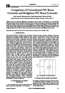
Fig.7 Loss analysis of converters.
Figure 7 shows loss comparisons among the three converters. The total efficiency of the proposed converter is increased by 0.7 % comparing to the CCM. The largest difference shown in the loss is the boost inductor loss. DCM shows the largest in the boost inductor loss because the peak current is the highest among these converters. (Refer to Table 3). In the proposed converter, although the peak current is equal to CCM, the amount of current flows into the boost-up inductor is nearly quarter of the CCM. Figure 8 shows a study on the losses among the boost choppers (conventional circuits) and the active buffer (proposed converter). The loss of the active buffer is decreased by 10 to 20 % in compared with the conventional boost choppers. In particular, even the number of switches is increased in the active buffer, but the current passing through the active buffer is quarter of the input current. Therefore the conduction loss is decreased. V.
DESIGN OF CONVERTER VOLUME
A. Inductor The design of the inductor volume can be calculated by using an area product method [7]. The area product Ap is defined as following Ap = Ae Aw ,
Fig.8 Detail loss analysis of PFC converters.
Ae
(17)
where Ae is the cross-sectional area of magnetic core, Aw is the cross-sectional area of the winding wire as shown Fig. 9. The area product Ap can obtain the volume due to bisect Ae and Aw at right angles. The volume of an inductor can be related to the area product Ap. The relationship is derived according to
D
D
A
B
Aw A C D
Fig.9 Design of core.
519
B
Fig. 11 Simplified thermal model.
Capacitance [ F]
Fig. 10 Relationship between the inductor volume and the area products.
(a)Volume of capacitor versus capacitance
(b) Capacitance versus Rated ripple current
(c)Volume of capacitor versus rated ripple current Fig. 12 Relationship among volume of capacitor, capacitance and rated ripple current. 3
VL = K V A p 4 ,
Figure 10 shows the relationship between the inductor volume and the area products. From (18), (19), the volume of an inductor is proportional to the three-quarters power of the stored energy in the inductor. In this specification, the volume of the boost inductor in the active buffer can be decreased by 70% lower than the standard boost chopper.
(18)
where KV is a constant related to core configuration values. The area product of an inductor is obtained as Ap =
2W m , K u Bm J w
(19)
B. Heat sink Heat sinks are designed by concerning about the power density. At first, we calculate the cooling system performance index (CSPI) [8],[9] as
where Wm, Ku, Bm and Jw are the energy stored in the inductor, the utilization factor, amplitude of a magnetic flax density in the core, and the amplitude in the current density of the winding conductor, respectively.
CSPI =
We designed a magnetic ferrite C-core based on the following parameters as shown in Fig.9: Kv = 19.2 (the rated A : B and C : D is set to 1:3), Ku = 0.5 Bm = 0.8 T and Jw = 4 A/mm2.
1 . RthVF
(20)
Figure 11 shows a simplified thermal model. Parameters of resistance Rth_j-c and Rth_c-f are obtained from the data sheet. Rthf is calculated from (20) with loss analysis data.
520
In this paper, the heat sink is designed to meet the following specifications: CSPI = 5, Junction temperature = 125 °C, ambient temperature = 40 °C.
800 600
C. Capacitor The design of the capacitor volume is difficult to indicate by mathematical expression. Therefore, the capacitor volume is designed based on the available market products. Figure 12 presents three different types of capacitor that can be utilized as a DC capacitor. As can be seen in Fig. 12(a), the volume of these capacitors is proportional to the capacitance. The smallest capacitor for the proposed converter is shown in Fig. 12(a). Notice that the selection of the electrolytic capacitor must consider upon its rated ripple current. Therefore, the large capacitor of conventional converter must select in fig 12(b), and Fig. 12(c).
400
Inductor Capacitor
200
Heat sink
0
Input filter Proposed circuit
Conventional Conventional circuit circuit (CCM) (DCM)
Fig.13 Total volume of passive components Table 3 Comparison of the conventional CCM, DCM and proposed converter.
Figure 13 show the total volume of the passives components implemented in the conventional converters and the proposed converter. The total volume of the proposed converter is shown to decrease by 0.6 times in compared with the conventional converter. In particular, the volume of the active buffer, which includes of the boost inductor and the DC capacitor, can be reduced by approximately 60% than that of the standard boost chopper. Table 3 shows the comparison among these converters. The efficiency of the proposed circuit is higher than the conventional circuits even the amounts of switches are increased in the proposed circuit. In addition, volume of the proposed converter is smaller than conventional circuits due to the decrement on the inductor size. VI.
[3]
Sangsun Kim; Enjeti, P.N.; “Control of multiple single-phase PFC modules with a single low-cost DSP” in Industry Applications, IEEE Transactions, Vol. 39, Issue: 5, 2003 , Page(s): 1379 – 1385. [4] Shimizu, T. Wada, K. Nakamura, N. " Flyback-Type Single-Phase Utility Interactive Inverter With Power Pulsation Decoupling on the DC Input for an AC Photovoltaic Module System " Power Electronics, IEEE Transactions on Issue Date: Sept. 2006 Volume: 21 Issue: 5, pp. 1264 - 1272, (2006) [5] Kuo-Hen Chao; Po-Tai Cheng; Shimizu, T. “New control methods for single phase PWM regenerative rectifier with power decoupling function” Power Electronics and Drive Systems, 2009. PEDS 2009. International Conference on, pp. 1091 - 1096. [6] Y. Ohnuma, J. Itoh; “A control method for a single-to-three-phase power converter with an active buffer and a charge circuit” Energy Conversion Congress and Exposition (ECCE), 2010 IEEE, pp. 1801 1807. [7] C. W.T McLyman, “Magnetic Core Selection for Transformer and Inductors, 2nd Ed., New York, NY: Marcel Dekker, 1997. [8] Kazimierczuk, M.K.; Sekiya, H.; “Design of AC resonant inductors using area product method” Energy Conversion Congress and Exposition, 2009. ECCE 2009. IEEE pp. 994 - 1001. [9] U. Drofenk, G. Laimer, and J. W. Kolar, “Theroretical Converter Power Density Limits for Forced Convection Cooling” in PCIM Europe 2005, pp. 608-619. [10] Kolar, J.W.; Drofenik, U.; Biela, J.; Heldwein, M.L.; Ertl, H.; Friedli, T.; Round, S.D.; “PWM Converter Power Density Barriers” in Power Conversion Conference - Nagoya, 2007. PCC '07, pp. 9 - 29.
CONCLUSION
This paper compares the efficiency and the volume between several single-to-three-phase PFC converters. The efficiency of the proposed converter is highest efficiency and smallest volume of these converters. In particular, the proposed converter is 1.5% higher than the conventional converter with DCM. In addition, the total volume of the proposed converter is reduced by 0.7 times than that of the conventional converter with CCM. Therefore, the converter can achieve downsizing and high-efficiency by using the proposed active buffer. ACKNOWLEDGMENT This study was supported by Industrial Technology Grant Program in 2009 from New Energy and Industrial Technology Development Organization (NEDO) of Japan. REFERENCES [1]
[2]
Zhonghui Bing; Min Chen; Miller, S.K.T.; Nishida, Y.; Jian Sun; “Recent Developments in Single-Phase Power Factor Correction” in Power Conversion Conference - Nagoya, 2007. PCC '07, pp. 1520 1526. Crebier, J.-C.; Revol, B.; Ferrieux, J.P.; “Boost-chopper-derived PFC rectifiers: interest and reality” in Industrial Electronics, IEEE Transactions, Vol. 52, Issue: 1, 2005 , Page(s): 36 – 45.
521