COMPARISON OF CAPABILITIES OF FINITE ELEMENT METHOD AND SPECIALIZED SOFTWARE PROGRAMS IN EVALUATION OF GEARS VACLAVA LASOVA, PETR BERNARDIN, EVA KRONEROVA University of West Bohemia, Faculty of Mechanical Engineering, Department of Machine Design, Pilsen, Czech Republic DOI: 10.17973/MMSJ.2015_06_201515 e-mail:
[email protected] When performing the evaluation of engineering structures, today’s designers fully depend on software tools available to their employer. The choice of a software program for design calculations and evaluation of structural elements is typically dictated by its price. Where the demand for engineering design services involves simple structures, the designers turn to single-purpose programs based on engineering tables or databases, particularly in small companies. Finite element method (FEM)-based tools for structural analysis are much less affordable. Also, the time required for FEM analysis is considerably longer than with other methods. As the available design completion times tend to be short, designers typically have to rely on specialized programs (MITCalc, KISSsoft, Autodesk Inventor or PREV). Consequently, they have no other choice but to accept the information and values obtained from these calculation programs, even without understanding their principles. KEYWORDS gear calculation, mesh, finite element analysis, root safety, flank safety 1. INTRODUCTION The purpose of this study is to present the capabilities of the aforementioned affordable programs, the FEM method and analytical solutions in calculating and evaluating structural elements and mechanisms. One section of this paper is devoted to comparing the programs with respect to materials parameters, loading states, evaluation criteria and results. A detailed comparison was undertaken for a specific spur gear train. The gear strength analysis was carried out using analytical software tools [MITCalc 2003-2013, KISSsoft AG 1998-2014, and PREV 1992] and the finite element method. The results of these various approaches were compared. Different methods (based on applicable standards) may be employed in these calculations. Safety
Units
ČSN ČSN 12050.6 14220.4
Density
ρ
[kg/m3]
7870
Tensile Strength
Rm
[MPa]
640
785
Tensile Strength, Yield
Re
[MPa]
390
588
7870
Tooth Hardness – Core
JHV
[HV]
200
250
Tooth Hardness – Side
VHV
[HV]
0
650
Contact Fatigue Limit
SHlim
[MPa]
520
1270
Bending Fatigue Limit
SFlim
[MPa]
410
700
Young‘s Modulus (Modulus of Elasticity)
E
[GPa]
206
206
Poison‘s Ratio
ν
[–]
0.3
0.3
Table 1. Input parameters for the strength check using the Inventor software, KISSsoft Parameter
Symbol
Unit
Pinion
Wheel
Power
P
[kW]
3
2.971
Speed
n
[min –1]
20
9.5
Number of teeth
z
[–]
20
42
Correction
x1
[–]
0
0
Helix angle
β
[°]
0
Pure-rolling centre distance
aw
[mm]
372 2.1
0
Gear ratio
i
[–]
Module
m
[mm]
12
Gear width
b
[mm]
80
Life
Lh
[hrs]
Material
5000 12050.6
14220.4
Table 2. Input parameters for the strength check using the Inventor software, KISSsoft
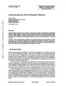
factors may vary, depending on the gear shape, method of manufacture, life, notch sensitivity or load pattern. These factors affect the calculation of the contact fatigue strength, bending fatigue strength and the relevant allowed stress. Their ratios define the pitting sH and bending safety factors sF,. Those are the key parameters in gear design where failures due to pitting induced by the contact between the teeth and due to bending loads at the tooth root must be prevented. The finite element method calculation used here did not include the evaluation step. It was only employed to find the local stresses caused by the bending load at the tooth root and the pressure along the line of contact on the pitch circle. The conclusion compares the safety factors obtained by means of the various software programs. Stress levels calculated using the aforementioned programs and the FEM method are compared as well. Gear Wheel Parameters In order to check the gear wheel design with regard to pitting resistance and bending strength, one has to provide inputs including the wheel size, module, number of teeth, gear width and service load parameters, as shown in Table 2. These parameters were used for developing a 3D model and in calculations using KISSsoft, MITCalc and PREV programs. Detailed materials data for the pinion and the wheel are given in Table 1 which lists relevant materials characteristics. The wheel is made of the CSN 14220.4 steel and the pinion material is the CSN 12050.6 steel. Finite Element Analysis Gearing calculations using the FEM method are not often used when designing gear boxes in practice. In this case the numerical calculation was made as comparative. The contact task considering the linear behaviour of material took on a standard computer 10 minutes, the discretization error of the task, which is dependent on the fineness of the used network, was in normal below 10 %, so the results can be considered to be accurate enough for comparing with analytical calculations. Figure 1 shows the meshes in both gears. For the calculation, it was necessary to define the shaft and its bedding points as infinitely rigid
Figure 1. Mesh generation
610 | 2015 | JUNE |
Symbol
SCIENCE JOURNAL
bodies. The ideal model of the shaft was built of 1D RBE2 elements. At the points of contact between the gears, fine mesh of CHEXA (20) elements was applied. In the tooth interior, CTETRA (10) elements were used. Transition regions between areas with dissimilar elements were built of pyramid elements. The torque is transmitted between the gears through contact areas on their teeth. If more accurate results were required, a non-linear analysis involving a bilinear characteristic of the sub-surface layer on the tooth face and flank would be necessary to use.
[4] Where KF denotes the additional load factor, b is the wheel width, mn denotes the module, and Fo stands for the tangential force [5] Calculation of the bending safety factor sF [6] The Y, Z, K coefficients with relevant indices used in the formulas above are described in detail in Table 3, where their names, symbols and values in individual software programs are given. Safety factors KA
Figure 2. Bending stress at the tooth root in the pinion and the wheel
K Hv
Using the FEM computation, bending stresses (at the tooth root) σF and contact stresses (on the pitch circle)σH were found in the pinion and the wheel. Ideally, these stress levels should be equal to those found by the analytical solution specified in the standard ČSN 01 4686 [4] and corrected with applicable coefficients.
K Hβ KHα K Fβ K Fα
Name
PREV
KISSsoft ISO 6336:2006 Method B
MITCalc ISO 6336
Application factor Dynamic factor Face load factor (contact stress) Transverse load factor (contact stress) Face load factor (root stress) Transverse load factor (root stress)
1
1
1
1.01
1.003
1.005
1.2/1.27
1.158
1.067
1
1.18
1
1.16/1.22
1.107
1.054
1.3/1.57
1.18
1
For pitting safety calculation ZE ZH Zε Zβ ZN
Figure 3. Contact stress on the pitch circle of the pinion and the wheel
ZL
Comparison with Results of Calculations Using KISSsoft, MITCalc and PREV The purpose of this study is to acquire useful knowledge for checking the strength of gear wheels with the aid of affordable software tools. Calculation procedures for the examined programs are based on the CSN 01 4686 standard. This standard uses the Hertz pressure at the pitch point as the contact strength criterion.
ZR Zv ZB ZW
YSa Yβ
where σHO is the nominal contact stress
Yε
[1] Where KH stands for the additional load factor, Fo is the tangential force, bw is the gear train width, d1 is the pitch circle diameter and i stands for the gear ratio [2] Calculation of the pitting safety factor sH [3]
189.8
189.812
189.81
2.495
2.495
2.495
0.89
0.887
0.887
1
1
1
1.6
1.174/1.242
1.236/1.331
1
1.025/1.02
1.213/1.113
1
0.96/0.967
0.84/0.911
1
0.917/0.931
0.877/0.942
1
1.06/1
1.065/1
1
1.051/1
1
For bending safety calculation YFa
The formula expressing the Hertz pressure at the pitch point is
Elasticity factor Zone factor Contact ratio factor Helix angle factor Life factor for contact stress Lubricant factor Roughness factor affecting surface durability Peripheral speed factor Single pair tooth contact factor Work hardening factor
YN YR YX Yδ
Form factor (bending) Stress correction factor Helix angle factor Contact ratio factor Life factor for bending stress Tooth-root surface factor Size factor Notch sensitivity factor
2.8/2.37
1.59/1.37
3.036/2.593
1.48/1.57
1.82/1.99
1.523/1.64
1
1
1
0.69
1
0.707
1/1.01
0.986/1.006
0.926/1.005
0.957
0.957/0.957
0.931/0.969
1
0.958/0.93
0.958/0.93
1.07/1.11
0.972/0.995
0.976/0.992
Table 3. Inpuat parameters for the strength check using the Inventor, KISSsoft, and MITCalc software programs
The formulas for safety factor calculations are identical in all three software programs, as those are based on a single standard. The names of Y, K and Z coefficients (including applicable indices) are the
2015 | JUNE |
SCIENCE JOURNAL | 611
Stresses
FEM
KISSsoft
MITCalc
Discrepancy KISSsoft vs. FEM (%)
Discrepancy MITCalc vs. FEM (%)
Discrepancy MITCalc vs. KISSsoft (%)
σF
64.01 MPa
58.76 MPa
43.1 MPa
8.2
32.66
26.65
σH
560.5 MPa
560 MPa
443.5 MPa
0.08
20.87
20.80
σFG
X
720.4 MPa
330.3 MPa
X
X
54.15
σHG
X
578.19 MPa
574.1 MPa
X
X
37.52
Table 4. Values and discrepancies between stresses in the pinion Stresses
FEM
KISSsoft
MITCalc
Discrepancy KISSsoft vs. FEM (%)
Discrepancy MITCalc vs. FEM (%)
Discrepancy MITCalc vs. KISSsoft (%)
σF
56.15 MPa
55.47 MPa
39.66 MPa
1.21
29.36
28.5
σH
479.9 MPa
526 MPa
416.7 MPa
-9.60
13.16
20.77
σFG
X
1247 MPa
628.91 MPa
49.56
X
49.56
σHG
X
1448 MPa
1615.6 MPa
-11.57
X
-11.57
Table 5. Values and discrepancies between stresses in the wheel Safety factors
KISSsoft
MITCalc
PREV
SF
12.26
7.66
7.55
Discrepancy KISSsoft vs. PREV (%) Discrepancy KISSsoft vs. MITCalc (%) Discrepancy MITCalc vs. PREV (%) 38.41
37.52
1.43
SH
1.03
1.29
1.36
-32.03
-25.24
-5.42
Table 6. Values and discrepancies between pitting and bending safety factors in the pinion Safety factors
KISSsoft
MITCalc
PREV
Discrepancy KISSsoft vs. PREV (%)
Discrepancy KISSsoft vs. MITCalc (%)
Discrepancy MITCalc vs. PREV (%)
SF
22.49
15.86
12.66
43.7
29.47
20.17
SH
2.75
3.88
3.98
-44.72
-41.09
-2.57
Table 7. Values and discrepancies between pitting and bending safety factors in the wheel
same in most cases. Some coefficients, however, may have different names. The differences, for the most part, are only in their symbols or, perhaps, there may be different combinations of coefficients in the various software programs. More substantial differences are encountered in the calculation of allowed stresses – tooth-root stress limit σFG and pitting stress limit σHG. Minor differences can be found in nominal stress calculations. In general, the software programs use identical methods for determining the forces against the teeth but differ in the values of coefficients and, most importantly, in the stress evaluation. Stress results are summarized in Table 4 and 5. The above-listed pitting and bending safety factors given in Tables 6 and 7 are comparable in MITCalc and PREV software tools. The bending safety factor in KISSsoft differs more substantially from those in the other programs. On the other hand, the pitting safety factor is comparable with the others. The differences are due to the YFa – Form factor (bending). It affects the calculation of the YFS coefficient and, in turn, the stress and safety factor magnitudes. Table 3 shows that its value is approximately twice lower in KISSsoft than in MITCalc and PREV. The discrepancies in values of both safety factors are caused by the coefficients defined in particular software programs or by the limitations on the selection of coefficient values. The software programs also recommend certain minimum levels of pitting SHmin and bending SFmin safety factors. In MITCalc and PREV, these limit values are approximately equal. KISSsoft, however, suggests substantially lower values. The minimum safety factor levels are the engineering designer’s choice.
KISSsoft MITCalc PREV
SHmin 1 1.3 1.2
SFmin 1.4 1.6 1.7
Table 8. Recommended minimum factors of safety for pitting and bending in individual software programs
CONCLUSION The merits of the present paper include the comparison of results using different software programs for gearing designs. During stress
612 | 2015 | JUNE |
SCIENCE JOURNAL
calculation at the tooth root σF and on the pitch circle σH the KISSsoft program corresponds to the FEM results. The MITCalc program shows a greater discrepancy, the calculated voltage is lower. For both analytical calculations further allowable stress in contact and bending is defined (σFg and σHg). The largest discrepancies were found between the σFG values. Here, the difference between KISSsoft and MITCalc results is twice as large. This is no random result. A number of followup calculations were carried out. In all cases, identical differences between σFG values obtained with KISSsoft and MITCalc programs were obtained. The question is if it is not just an error in the program. However, this important difference of values has a direct impact on the resulting bending safety factor SF and increases the final dimensions. From this point of view we can say that the differences between the results obtained by analytical calculations are not fundamental. However, using the MitCalc program is conservative and the designed gears using this program are the most robust. ACKNOWLEDGEMENTS The work has been supported by Department of Machine Design (University of West Bohemia). REFERENCES [CNI 1998] Czech Normalization Istitute, CSN 01 4686-3. Strength calculation of helical and bevel gears. The control calculation of helical gears (in Czech), Prague: 1998 [KISSsoft AG1998-2014] KISSsoft, Bubikon: Available at: www.kisssoft.ch/ english/downloads/, 1998-2014. [MITCalc 2003-2013] MITCalc 1.7, Available at: www.mitcalc.com/en/ products.htm, 2003-2013. [PREV 1992] Skoda Machine Tool a.s., PREV (company proprietary software), Pilsen, 1992 CONTACTS Assoc. Prof. Ing. Vaclava Lasova, Ph.D. University of West Bohemia, Department of Machine Design Univerzitni 22, Pilsen, 30614, Czech Republic tel.: + 420 377 638 200, e-mail:
[email protected], www.kks.zcu.cz