International Conference on Renewable Energies and Power Quality (ICREPQ’16) Madrid (Spain), 4th to 6th May, 2016 Renewable Energy and Power Quality Journal (RE&PQJ) ISSN 2172-038 X, No.14 May 2016
Comparison of Fuzzy and Neuro-Fuzzy Controllers for Maximum Power Point Tracking of Photovoltaic Modules Jemaa AYMEN1, Zarrad ONS1, Aurelian CRĂCIUNESCU2 and Mihai POPESCU2 1
L’école Nationale d’ingénieurs de Monastir Université de Monastir Monastir, Tunisia e-mail:
[email protected],
[email protected] 2
Electrical Engineering Faculty University Politehnica of Bucharest Bucharest, Romania
[email protected],
[email protected]
In this paper, intelligent control techniques using fuzzy logic control and neuro-fuzzy logic control are associated to an MPPT controller in order to improve energy conversion efficiency. Simulation and analysis in Matlab/Simulink environment of these control techniques are presented, and its performances are evaluated.
Abstract. The paper make a comparison among two control methods for maximum power point tracking (MPPT) of a photovoltaic (PV) system under varying irradiation and temperature conditions: the fuzzy control method and the neuro-fuzzy control method. Both techniques have been simulated and analyzed by using Matlab/Simulink software. The power transitions at varying irradiation and temperature conditions are observed and the power tracking time realized by the fuzzy logic controller against the neurofuzzy logic controller has been evaluated.
2. THE MODEL AND CHARACTERSITICS OF A PV MODULE The PV cell equivalent electric circuit can be represented as in Fig. 1. It consists in an ideal current source (IPV), an ideal diode, a parallel resistor (RP) a series resistor (RS). The current source IPV is the light generated current which is directly proportional to the solar irradiation G (measured in W/m2). The series and the parallel resistances are representative for the voltage loss on the way to the cell terminals and for the cell’s leakage current, respectively.
Key words Photovoltaic Module; MPPT; Fuzzy Logic Controller; NeuroFuzzy Logic Controller; Matlab/Simulink models.
1. INTRODUCTION Electrical energy generated by Photovoltaic Power Plants is becoming increasingly important due to its advantages: incurring no fuel costs, not being polluting, required little maintenance, and emitting no noise, among others. The photovoltaic current-voltage (I-V) characteristic is nonlinear and changes with irradiation and temperature. There is a point on the I-V characteristic or on the power-voltage (PV) characteristic, called the Maximum Power Point (MPP), at which PV module produces the maximum output power corresponding to the current values of solar irradiation and cells’ module temperature. The state-of-the-art techniques to track the maximum available output powers of PV systems are called the maximum-power point tracking (MPPT). Controlling MPPT for the solar array is essential in a PV system in order to reduce the cost of yielded electrical energy. There are many techniques developed to implement MPPT; these techniques are different in their efficiency, speed, hardware implementation, cost, popularity.
https://doi.org/10.24084/repqj14.465
Fig. 1 Equivalent circuit of a PV cell
For a PV module, with ns cells in series and np cells in parallel, the characteristic I-V is given by the equation (1):
796
RE&PQJ, Vol.1, No.14, May 2016
3. THE MPPT CONTROL STRATEGIES
I n p I PV T npI0 C Tref
3
e
qE g 1 1 ak Tref TC
e
q V IRS akTC nS
V IR S 1 RP
(1)
where I0 is the reverse saturation current of the diode, Eg is the value of the energy band of the diode material, a is the ideality factor of the diode, k is the Boltzmann’s constant, q is the electron charge, and TC is cells’ temperature in Kelvin. The analyzed PV module has the electric specifications given in the TABLE 1. Rated Power Current at Maximum Point Voltage at Maximum Point Short circuit current Short circuit voltage Number of cells in parallel Number of cells in series
TABLE 1: Specific Data of BPMSX60 PV Module 60 W 3.25 A 16.8 V 3.56 A 21.6 V 1 36
In Fig. 3 is shown the block diagram of a PV module with MPPT controller. The controller performs a continuous research of the MPP, according to an appropriate algorithm. During this research, the controller acts on the duty factor d of the DC-DC converter in a manner that allows to the instant load connected to the PV module to extract the maximum power which the PV module is capable of produce at the current solar irradiation G and module cells’ temperature TC. The photovoltaic module operation depends on the load characteristics at which it is connected to. So when connected to load directly, the output of the PV array rarely works at MPP. However, to adapt the load and extract maximum power from a PV module, a DC-DC boost converter is used by adjusting its duty cycle under control of the selected controller (in our case fuzzy and neuro-fuzzy algorithms) based MPPT controller such that the maximum solar panel output power is extracted under all operating conditions. In Fig. 3, DC-DC converter is a step-up power converter. The power flow through DC-DC converter is controlled by varying the duty factor d. The relationship between input and output voltages of DC-DC converter is given by equation (2):
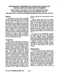
For various values of the solar irradiance G, and cells’ temperature TC, the I-V characteristics of the analyzed PV module are shown in Fig. 2.
VO 1 VI 1 d
(2)
where VO is the output voltage and VI is the input voltage of the boost converter. A. The MPPT Controller With Fuzzy Logic The general structure of a controller algorithm based on fuzzy logic consists of three stages: fuzzification, rule base and defuzzification. During fuzzification, numerical input variables are converted into linguistic variable based on a membership function. For the MPPT controller with fuzzy logic, the inputs are taken as a change in power and voltage as well. There is a block for calculating the error (E) and the change of the error (dE) at sampling instants k: a)
E k
dP Pk Pk 1 dV V k V k 1
dE k E k E k 1
(3) (4)
where P(k) is the power of delivered by PV module and V(k) is the terminal voltage of the module. Value of the error E(k) determines the MPPT controller output according to the sign. By example, if the operating point is located to the left of the MPP of the characteristic (P-V), the sign of the error E(k) is positive and the reported load resistance to the PV terminal have to be increased. As a consequence, the duty factor d has to be decreased. Also, in order to avoid the final oscillations around the MPP, when
b) Fig. 2 The PV module PV characteristics for various values of G, and TC = 25 0C (a) and for G = 1000 W/m2 and various values of TC (b).
https://doi.org/10.24084/repqj14.465
797
RE&PQJ, Vol.1, No.14, May 2016
Fig. 5 Matlab/Simulink window of the Fuzzy Logic Controller
Fig. 3 The block diagram of a PV module with MPPT controller
In Fig. 6 is shown the structure of the fuzzy controller used from Simulink library.
the change of the error dE(k) decreases, the speed of convergence to the operating point has to be reduced. As a consequence, the decreasing increment of the duty factor has to be reduced. This is the way the MPPT controller can decide what will be the variation of the duty cycle that must be impose on the DC-DC boost converter to approach MPP. Once E(k) and dE(k) are calculated and converted to the linguistic variables, the fuzzy logic controller output, which is duty ratio d of the power converter, can be looked up in a rule base table. The linguistic variables assigned to the duty factor d for the different combinations of E(k) and dE(k) was established according to our knowledge.
Fig. 6 Simulink Model of a fuzzy logic controller with Rule viewer
In the defuzzification stage, the fuzzy logic controller output is converted from a linguistic variable to a numerical variable still using a membership function.
1) The Fuzzification: The following linguistic variables have been used for the MPPT fuzzy controller: PG (positive big), PP (Positive Small), ZE (Zero), NP (negative small), NG (large negative).
In Matlab/Simulink environment, there is a Fuzzy Toolbox that allows to the user to manage this structure and formulate fuzzy rules. Using this tool the user can program the command used subsequently in the block Fuzzy Logic Controller with Rule viewer.
The generation of the membership functions of these variables was performed based on user experience. After several tests under different atmospheric conditions, the E(k) and dE(k) variables have been defined for solving continuing problems of maximum power point. The five membership functions are given in Fig.7.
In Fig. 4 is shown the Matlab/Simulink model of a PV module with MPPT fuzzy logic controller, and in Fig. 5 is shown the Fuzzy Logic Matlab/Simulink windows which make up the MPPT controller (its inputs E(k) and dE(k), its output d and different parameters of the fuzzification, involving the aggregation and the defuzzification can be monitorized from this window).
2) The Inference Rules: For the MPPT fuzzy controller it was chosen the Mamdani type inference rules with logical operators MIN and MAX. These rules are introduced into the controller to obtain the right decision for its output d. In the TABLE 2 are shown the selected rules: TABLE 2: The Fuzzy Logic Controller Inference Rules
E NG NP ZE PG PP NG
dE NG PG PG PP NP NG PG
NP PG PP PP NP NP PG
ZE PG PP ZE NP NP PG
PG PG PP NP NP NP PG
Fig. 4 Simulink model of the PV module with MPPT fuzzy logic controller
https://doi.org/10.24084/repqj14.465
798
RE&PQJ, Vol.1, No.14, May 2016
PP PG ZE NP NP ZE PG
TABLE 3: Simulation results of Pmax checking with fuzzy and neuro-fuzzy controllers in comparison with theoretical values. Pmax [W]
Fig. 7 The membership functions of variables E(k) and dE(k)
G [W/m2]
T [°K]
Fuzzy Controller
NeuroFuzzy Controller
Theoretical values
1000 900 800 700 600
300 295 290 285 280
50,261 45,738 40,849 35,614 30,133
50.262 45.736 40.856 35.633 30.156
50,262 45,739 40,874 35,709 30,251
4. SIMULATION RESULTS In TABLE 3 are given the theoretical and simulation results obtained with Fuzzy and Neuro-Fuzzy Controller, in checking the MPP of the analyzed PV module, for various values of solar irradiation G and cells’ temperature T.
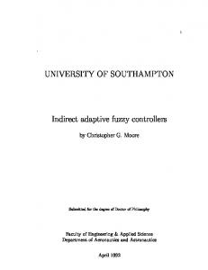
3) The Defuzzification: This operation converts the inferred fuzzy control action into a numerical value at the output by forming the union of the outputs resulting from each rule. The method of the gravity center has been chosen for the defuzzification. In the Fig. 8 is shown the surface output d = f (E, dE) of the MPPT controller.
The Figure 10 and 11 shows the evolution of the power produced by the PV module delivered MPP checking by the considered algorithms, under the solar irradiation G = 1000 W/m2 and PV cells’ temperature TC = 300 0K.
B. The MPPT controller with neuro-fuzzy logic This simulation is based essentially on the Matlab/Simulink toolbox ANFIS that combines in its structure five layers on a Fuzzy Inference System type Sugeno and, also, the possibility of introducing a learning table to take the advantage of the neuron network approach when passing from one layer to another. In order to implement the MPPT neuro-fuzzy controller, for each of the two inputs E and dE were chosen five membership functions and was created a knowledge base. After the learning table has been loaded, for each input pair (E, dE) adequate
Fig. 9 Surface Rule Viewer of Neuro-Fuzzy controller
Fig. 8 The surface d = f (E, dE) of the MPPT controller output.
output d = f (E, dE) were described, and file created in the fuzzy toolbox has been made, the neuronal structure was obtained. At this stage the Fuzzy and the learning table are loaded, and one can start learning to get the outputs generated by the ANFIS. In the Figure 9 is shown the surface of the MPPT neuro-fuzzy controller output d based on the appropriate entries.
https://doi.org/10.24084/repqj14.465
Fig. 10 The power evolution during MPP checking by the fuzzy algorithm.
799
RE&PQJ, Vol.1, No.14, May 2016
[8]
[9]
[10]
Fig. 11 The power evolution during MPP checking by the neuro-fuzzy algorithm.
5. Conclusion
[11]
Two MPPT control strategies based on Fuzzy Logic and Neuro-Fuzzy logic have been compared. It is found that the control of the DC / DC by the Neuro-Fuzzy approach more reliable than the other approach as it combines fuzzy logic and neural networks to extract the maximum power point, taking advantage of the flexibility of the first and the learning capacity of the second.
[12]
[13]
Acknowledgement [14]
This work was realized through the Partnership program in priority domains - PN II, developed with support from ANCS CNDI - UEFISCDI, project no. PN-II-PT-PCCA-2011-3.21670.
[15]
References [1]
[2]
[3]
[4]
[5]
[6]
[7]
[16]
Y. T. Hsiao; C. H. Chen; "Maximum power tracking for photovoltaic power system," Industry Applications Conference, vol.2, pp. 10351040, 2002. V. Salas, E. Ol´ıas, A. Barrado, and A. L´azaro, “Review of the maximum power point tracking algorithms for stand-alone photovoltaic systems,” Solar Energy Materials and Solar Cells, vol. 90, no. 11, pp. 1555–1578, 2006. Kottas, T.L.; Boutalis, Y.S.; Karlis, A.D.; "New maximum power point tracker for PV arrays using fuzzy controller in close cooperation with fuzzy cognitive networks," IEEE Transactions on Energy Conversion, , vol.21, no.3, pp.793-803, Sept. 2006. T. Esram, P. L. Chapman, ”Comparison of Photovoltaic Array Maximum Power Point Tracking Techniques”, IEEE Transactions on Energy Conversion, vol.22, no.2, pp.439-449, June 2007. A. Dolara, R. Faranda, S. Leva., ”Energy Comparison of Seven MPPT Techniques for PV Systems”, Journal of Electromagnetic Analysis and Applications, vol.1, no.3, pp.152-162, Sep 2009. M.Hatti, IEEE Member, A. Meharrar, M.Tioursi; "Novel Approach of Maximum Power Point Tracking for Photovoltaic Module Neural Network based",2-4 November 2010, Ghardaïa, Algeria. Revankar, P.S.; Gandhare, W.Z.; Thosar, A.G.; "Maximum Power Point Tracking for PV Systems Using MATALAB/SIMULINK," Second
https://doi.org/10.24084/repqj14.465
[17]
[18]
[19]
[20]
800
International Conference on Machine Learning and Computing (ICMLC), pp.8-11, 9-11 Feb. 2010. H. N. Zainudin and S. Mekhilef, “Comparison study of maximum power point tracker techniques for PV systems,” in Proceedings of the 14th International Middle East Power Systems Conference (MEPCON ’10), Cairo, Egypt, 2010. Seok-Il Go, Seon-Ju Ahn, Joon-Ho Choi, Won-Wook Jung, Sang-Yun Yun, Il-Keun Song, "Simulation and Analysis of Existing MPPT Control Methods in a PV Generation System", Journal of International Council on Electrical Engineering vol.1, no.4, pp.446-451, Oct 2011. Seok-Il Go, Seon-Ju Ahn, Joon-Ho Choi, Won-Wook Jung, Sang-Yun Yun, Il-Keun Song, "Simulation and Analysis of Existing MPPT Control Methods in a PV Generation System", Journal of International Council on Electrical Engineering vol.1, no.4, pp.446-451, Oct 2011. A. Panda ,M.K.Pathak, S.P.Srivastava, “Fuzzy Intelligent Controller for the Maximum Power Point Tracking of a Photovoltaic Module at Varying Atmospheric Conditions”, Journal of Energy Technologies and Policy, www.iiste.org, ISSN 2224-3232 (Paper) ISSN 2225-0573 (Online), Vol.1, No.2, 2011. C. Ben Salah, M. Ouali, "Comparison of Fuzzy Logic and Neural Network in Maximum Power Point Tracker for PV Systems", Elsevier, Electric Power Systems Research, vol.81, pp.43-50, July 2011. M. Salhi, R. El-Bachtri, "Maximum Power Point Tracker Using Fuzzy Control for Photovoltaic System", International Journal of Research and Reviews in Electrical and Computer Engineering, vol.1, no.2, pp.69-75, June 2011. H.E.A. Ibrahim, M. Ibrahim, “Comparison Between Fuzzy and P&O Control for MPPT for Photovoltaic System Using Boost Converter”, Journal of Energy Technologies and Policy www.iiste.org, ISSN 22243232 (Paper) ISSN 2225-0573 (Online), Vol.2, No.6, 2012. M. M. Algazar, H. Al-Monier, H. A. El-Halim, and M. E. E. K. Salem, “Maximum power point tracking using fuzzy logic control,” International Journal of Electrical Power and Energy Systems, vol. 39, no. 1, pp. 21–28, 2012. H.E.A. Ibrahim, "Comparison Between Fuzzy and P&O Control for MPPT for Photovoltaic System Using Boost Converter", Journal of Energy Technologies and Policy, Vol.2, No.6, 2012, ISSN 2224-3232 (Paper). M. F. Ansari, S. Chatterji, and A. Iqbal, “Fuzzy logic-based MPPT controllers for three-phase grid-connected inverters,” International Journal of Sustainable Energy, vol. 32, no. 3, 2013. S. Shamshul Haq, B. Wilson Shyamsunder, G. Mohammad Zameer, "Design and simulation of MPPT algorithm of photovoltaic system using intelligent controller", International Journal of Advanced Scientific and Technical Research, Issue 3 volume 6, Nov.-Dec. 2013 ISSN 2249-9954. Y. H. Liu, C. L. Liu, J. W. Huang, J. H. Chen, “Neural-network-based maximum power point tracking methods for photovoltaic systems operating under fast changing environments”, Solar Energy 89, (2013), 42-53. H. Mahamudul, M. Saad and M. I. Henk, “Photovoltaic System Modeling with Fuzzy Logic Based Maximum Power Point Tracking Algorithm”, International Journal of Photoenergy, Vol. 2013, ID 762946, http://dx.doi.org/10.1155/2013/762946.
RE&PQJ, Vol.1, No.14, May 2016