In this paper, the proposed ... factors in the past decades, there is still no effective solution. Most of the ... explanation or simply given some rough idea to guide the choice .... the constant gain blocks are used as scaling factors GE, GCE and.
©2010 International Journal of Computer Applications (0975 – 8887) Volume 1 – No. 11
Fuzzy Adaptive Controllers for Speed Control of PMSM Drive N. J. Patil
Dr. R. H. Chile
Dr. L. M. Waghmare
Assistant Professor D. N. Patel College of Engineering, Shahada, Maharashtra, India
Assistant Professor S. G. G. S. Institute of Engineering & Technology, Nanded, India
Professor S. G. G. S. Institute of Engineering & Technology, Nanded, India
ABSTRACT The objective of the Fuzzy Adaptive Control (FAC) is to tune the scaling factors of the direct fuzzy logic controller (FLC). In this novel approach output scaling factor of Fuzzy controller is tuned through adaptation mechanism. The idea is to have a control system that will be able to achieve improvement in tracking set point change and rejection of load disturbance. In this paper, the proposed Fuzzy Adaptive Controller is applied to a permanent magnet synchronous motor drive (PMSM). High performances and robustness have been achieved by using the FAC. This will be illustrated by simulation results and comparisons with other controllers such as PI; classical and fuzzy adaptive controller based on tuning of input and output scaling factors. The performance criteria selected is quadratic performance criteria in terms of Rise Time (RT), Settling Time (ST), Integral of square error (ISE) and Integral of absolute error (IAE).
Categories and Subject Descriptors J.7 [Computers in Other Systems] (C.3)
General Terms Algorithms, Design and Experimentation.
Keywords Fuzzy Logic, Adaptive Control, PMSM Drive, PI Controller.
1. INTRODUCTION As results of the progress in power electronics, software engineering, and materials, the PMSM, based on modern rare earth variety, becomes serious competitor to the induction motor and conventional wound rotor synchronous motor. PMSM drives are used in many applications. They are receiving increased attention because of their high torque density, high efficiency, and small size. The PMSM is preferred, in industrial servo applications, to the DC motor due to considerations of the cost, size, low maintenance, maximum speed capability, and simplicity of design. Fuzzy logic can be considered as a mathematical theory combining multi-valued logic, probability theory, and artificial intelligence to simulate the human approach in the solution of various problems by using an approximate reasoning to relate different data sets and to make decisions. In this paper, the adaptive control of fuzzy logic controller for a vector controlled PMSM is investigated. First FLC principle is presented and its application to the speed control is considered [1].
It has been reported that fuzzy controllers are more robust to plant parameter changes than classical PI or PID controllers and have better noise rejection capabilities. The proposed scheme exploits the simplicity of the Mamdani type fuzzy systems that are used in the design of the controller and adaptation mechanism. The fuzzy adaptive strategies are closer to the experts, reflecting their knowledge and experience. As the modern conventional control strategies grow in complexity, the fuzzy controllers are very competitive in high performance applications. As a result, the performance/complexity ratio is generally higher for adaptive fuzzy controllers [2]. There are many types of adaptive control techniques that exist today to assist control designers to develop adaptive speed controllers. Among them are the plant model- based Model Referencing Adaptive Control (MRAC) and Sliding Mode Control techniques as well as AI-based techniques such as Fuzzy and Neural Control [8]. Recent literature has paid much attention to the potential of fuzzy control in machine drive applications [56]. This is because it has the advantages of providing robust performance for both linear and nonlinear plant functions, and convenience as it does not require knowledge of the plant’s mathematical model [1-2, 10]. However, the qualitative design of the fuzzy logic controller (FLC) is entirely heuristic, and thus difficult to obtain a systematic design as it is based on one’s experiences and expert knowledge about the process being controlled [5]. Besides that, its input and output scaling gains are determined by trial and error, and has to be varied to tune the FLC for the desired performance, which altogether makes its design a time- consuming task [4-5]. To make the FLC self-adapting towards varying operating conditions, papers such as [6] and [9] have proposed that an additional FLC be included into the control algorithm. This entails more rules and instructions, and thus requiring more memory and time to execute. There is a lot of literature concerning fuzzy PI type controller to design its parameters and how to systematically determine those parameters. Among those efforts towards the parameter design, the Fuzzy Neural Network approach by Kwong [9] was one of the practical and successful methods to derive fuzzy rules and MFs. Although much effort has been devoted to the fuzzy scaling factors in the past decades, there is still no effective solution. Most of the research works on FLC have either neglected this issue by directly applying a set of scaling factors (SFs) without explanation or simply given some rough idea to guide the choice of the SFs to a specific problem, their adopted solutions are 91
©2010 International Journal of Computer Applications (0975 – 8887) Volume 1 – No. 11 essentially empirical and with the trial-and-error nature [8]. Different types of adaptive FLC’s such as self-tuning and selforganizing controllers have also been developed [9-12] and implemented for various practical processes. Of the various tunable parameters, SF’s have the highest priority due to their global effect on the control performance. However, relative importance of the input and output SF’s to the performance of a fuzzy logic control system is yet to be fully established [18]. An alternative approach in traditional adaptive control, which needs a rather accurate model of the system, is the FLC. A standard FLC is usually defined by a set of fuzzy parameters which specifies which control action to take for a given process state. It has been proved that the FLC can provide any nonlinear control action with proper choice of the parameters. In this way, the key issue to design an FLC is to well define its parameters such as the knowledge base and scaling factors. However, the optimal setting of parameters varies under different working conditions. When the parameters are fixed, ideal performance cannot be achieved in all cases. A solution to this problem is addressed by the adaptive FLC, whose aim is to maintain consistent performance of a system by adjusting the controller parameters adapting to varying conditions [2, 3]. A Fuzzy Adaptive Scheme is proposed in which the Adaptation mechanism is executed by fuzzy logic based on the error and change of error measured between the motor speed and the reference signal. The control performance of the adaptive fuzzy controller is evaluated by simulation for various operating conditions. A comparison between modified FAC using Output Scaling Factor, Input Scaling Factor, classical FLC, and fixed gain PI controller is presented by simulation results that verify appropriateness of the approach under various operating situations and provide the fast and robust control. This paper is organized as follows. In present section short introduction along with literature survey is done. In section 2 mathematical model of PMSM Drive is explained. In section 3 classical fuzzy logic controller is discussed. Fuzzy Adaptive Controller through tuning of input scaling factors is discussed in section 4. In section 5 Fuzzy Adaptive Controller (FAC) using output scaling is considered. In section 6 results are compared and conclusions are given to show impact of AFC to improve the results of PMSM Drive.
2. SYSTEM MODEL The well-established dq model of the wound rotor synchronous machine is easily adapted to study the performance of PMSM given in [17]. There is no difference between the back e.m.f. produced by a permanent magnet and that produced by an excited coil. Hence, the mathematical model of a PMSM is similar to that of the wound rotor synchronous machine. The stator dq equations in the rotor reference frame of the PMSM are:
Vd Vq
Rs
Id Iq
d dt
d
q r
q
(1)
d
The dq axis stator flux linkages are: d q
Ld 0
0 Lq
Id Iq
f
0
The model is nonlinear, because it contains product terms such as speed with id or iq which are stator variables.
Ld 0
0 d Id Lq dt I q
Vd Vq
Rs r Ld
Lq
Rs
Id Iq
0 r
f
(3) The dynamic behavior and electromagnetic torque equations are expressed by:
J d r p dt
f p
r
C em C st
(4)
(5) The dq model of PMSM has been used to examine the transient behavior of a high performances vector controlled PMSM servo drive. The direct or‘d’ axis is aligned with permanent magnet flux linkage phasor f, so that the quadrate or ‘q’ axis is orthogonally aligned with the resulting back e.m.f. phasor. If Id is forced to be zero, then: d
f
q
Lq I q
(6)
For constant flux operation, the electromagnetic torque is:
Cem
3 p 2
f
Iq
(7)
Torque equation for PMSM resembles that of the regular DC motor. Therefore, it may facilitate very efficiently the control of the machine. The motor currents are decomposed into Id and Iq components in the rotor based dq coordinates system. The maximum torque is obtained with Id = 0 which corresponds to the case when the rotor and stator fluxes are perpendicular. The operation of the drive is then similar to that of armature current controlled DC motor. The drive behavior can be described by a simplified model expressed in equation (7). The two term proportional integral (PI) controller account for more than 95% of installed automatic feedback controller. PI controller gave optimal control for 1st order system without delays. In their work Pillai and Krishnan [14] shown that PI controller is sufficient for control of PMSM Drive for given reference signal. The PI controller used in this work has the general form:
U (t ) K p e(t ) K I e(t ) dt (2)
r
(8)
The variable e(t) represents the tracking error, the difference between the desired value (r) and the actual output (y). PID controller will use this error signal. PID will take appropriate action according to the law and pass the signal (u) to the plant to 92
©2010 International Journal of Computer Applications (0975 – 8887) Volume 1 – No. 11 adjust the appropriate manipulated variable. For PMSM Drive we use gains Kp = 3.15, Ki = 0.4 The output of PMSM Drive with PI controller is illustrated in Fig.8 and Fig.9. The PI controller needs to be fine tuned to give the expected output from process for given set point and when a change in set point is applied.
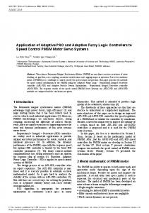
3. FUZZY LOGIC CONTROLLER Fig. 1 shows a block diagram of a speed control system using a FLC. The FLC has two inputs speed error e( k) and change in speed error de(k) and one output u(k) which represents the change in quadrature reference current Iq(k) .
e(k 1) y sp
y p (k 1)
(a) Input MF
(9)
de(k 1) e(k 1) e(k ) Fuzzy controller Inference mechanism
Reference input r(t)
Inputs u(t)
Process
outputs y(t)
Fig.3 Membership functions of the FLC
Rule-base
In the second stage of the FLC, the fuzzy variables E and dE are processed by an inference engine that executes a set of control rules contained in (7 7) rule bases. The control rules are formulated using the knowledge of the PMSM behavior. Each rule shown in Table 1 is expressed in the form
Figure 1. Block Diagram of Fuzzy Logic Controller To obtain normalized inputs and output for fuzzy logic controller, the constant gain blocks are used as scaling factors G E, GCE and GU as shown in Fig. 2.
E (k dE ( k U (k
1) 1) 1)
GE e( k
1)
GCE de( k Gu u ( k
1)
(10)
1)
The FLC consists of three stages: the fuzzification, rule execution, and defuzzification. In the first stage, the crisp variables e(k) and de( k) are converted into fuzzy variables E( k) and dE( k) using the triangular membership functions shown in Fig. 3. G
E
e
Fuzzy Logic Controller FLC
ce
(b) Output MF
G
U
U
u
Fuzzy
Fuzzy
G
CE
Figure 2. Scaling Factors Each universe of discourse is divided into five fuzzy sets: NB (negative big), NM (negative medium), NS (negative small), ZE (zero), PS (positive small), PM (positive medium) and PB (positive big). Each fuzzy variable is a member of the subsets with a degree of membership varying between [-1, 1].
Rule1 : IF x is A AND Y is B THEN Z is C Table 1 gives rules of fuzzy logic controller. Table 1 Rule Base for Fuzzy Logic Controller NB NM NS ZE PS PM
PB CE E NB NB NB NB NB NM NS ZE NM NB NB NB NM NS ZE PS NS NB NB NM NS ZE PS PM ZE NB NM NS ZE PS PM PB PS NM NS ZE PS PM PB PB PM NS ZE PS PM PB PB PB PB ZE PS PM PB PB PB PB Different inference algorithms can be used to produce the fuzzy set values for the output fuzzy variable uFuzzy. In this paper, the max-min inference algorithm is used, in which the membership degree is equal to the maximum of the product of E and dE membership degree. The inference engine output variable is converted into a crisp value UFUZZY in the defuzzification stage. Various defuzzification algorithms have been proposed in the literature. In this paper, the centroid defuzzification algorithm is used, in which the crisp value is calculated as the centre of gravity of the membership function. The definition of the spread of each partition, or conversely the width and symmetry of the membership functions, is generally a compromise between dynamic and steady state accuracy. Equally spaced partitions and consequently symmetrical triangles are a very reasonable choice. The universe of discourse is normalized over the interval [-1, 1]. So, we need to multiply the controller
93
©2010 International Journal of Computer Applications (0975 – 8887) Volume 1 – No. 11
Rule Base for
e
YSP
E
GE
d ce dt
CE
Fuzzy Rule Base
U
u GU
1 S
U
Y Process
GCE
Rule Base for
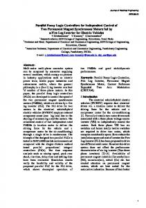
Figure 4. Fuzzy Adaptive Controller using Input Scaling Factors input and output variables by adjusting gains in order to accommodate these variables into the normalized intervals [3,4].
4. FUZZY ADAPTIVE CONTROLLER USING INPUT SCALING FACTORS
Thus the input gains of the auto tuning FLC does not remain fixed while the controller is in operating condition, infect it is updating at each sample by updating factors and .
4.2 Membership Functions
In fuzzy adaptive controllers the fuzzy controller parameters are continuously tuned. Two types of adaptation mechanism can be used. One method is to tune the rule base of the fuzzy controller, which has been done in our previous work. The other method is to tune the scaling factors. Now there are three scaling factors two input and one output. In this paper we can consider input scaling factor adaptation i.e. GE and GCE. The researchers have done lot of work on tuning of scaling factors but no exact methodology is available for selection of scaling factors. The method available is based on trial and error proposed and used by Seema Chopra and Kumar [15, 16] for input scaling factors and tested successfully up to second order system using transfer function approach. In this work the selected scaling factors are continuously tuned as per requirement of the fuzzy controller to produce the output for controlling PMSM Drive. Fig. 4 shows block diagram of Fuzzy Adaptive Controller using Input Scaling Factors.
Membership functions (MFs) for controller inputs (i.e., e and ce) and incremental change in controller output (i.e., cu) are defined on the common normalized domain [-1, 1] and are same as shown in Fig. 3. The MFs for are defined on the range [-1, 1] but with two fuzzy sets small and big and the MFs of corresponding to the singleton fuzzy sets and varies from [0, 1] as shown in Figure 5 (a) and 5 (b). It is assumed that is in the prescribed range and the appropriate range is determined by simulations.
4.1 Input Scaling Factors As per the above discussion FLC is proposed for the tuning of input scaling factors by developing the adjustment rules defined in terms of e and ce for updating the scaling factors, in dependence on the performance of the closed loop system. Auto tuning mechanism simply means that the self-tuning of input gains based on error and change in error. Based on this mechanism, the incremental change in e and ce is obtained by following equation.
(a) Membership Function for
(11) and where and are the updating factors for incremental change in e and ce which are computed online based on fuzzy logic reasoning using the error and change in error at each sampling time.
(b) Membership Function for Figure 5. Membership Functions for Fuzzy Adaptive Controller using Input Scaling Factors
94
©2010 International Journal of Computer Applications (0975 – 8887) Volume 1 – No. 11
4.3 Rule Base The rule base used for control output u is same as for the conventional fuzzy controller. In this method of updating factors and , we derive the rules experimentally based on the step response of the process. The evaluation performances measures are peak overshoot (OV), Rise time (RT) and settling time (ST), ISE and IAE. For example, if the system response is slower than desired, i.e. RT is positive, and then it really needs to increase the effect of error on the system and decrease the effect of derivative error. If e is +ve (PB, PM or PS) and ce is –ve (NB, NM or NS) then is B and is S. Then input scaling factors GE increases and GCE decreases. Similarly, if the overshoot or amplitude of oscillation is higher, then decrease the effect of error and increase the effect of derivative of error on the controller. If e is NB and CE is ZE then is S and is VB. Thus the input-scaling factor GCE is increased in this case. The other rules could be explained similarly. The effectiveness of tuning based on scaling factors is sometimes bounded by the contradictory requirements in these factors resulting from different performance measures. Table 2 Rule Base for CE E NB NM NS ZE PS PM PB
NB
NM
NS
ZE
PS
PM
PB
B S S S S S B
B B S S S B B
B B B S B B B
B B B B B B B
B B B S B B B
B B S S S B B
B S S S S S B
Table 3 Rule Base for CE E NB NM NS ZE PS PM PB
change in error. Many such controllers have been discussed in literature [11], [12]. The Adaptive Fuzzy controller that we investigated was first proposed by Mudi, and Pal [13]. The output gain (GU) of this controller is adjusted online depending on the present values of error and error derivative.
5.1 Input Scaling Factors The proposed controller is of self-tuning type. For the conventional fuzzy controller the controller output is mapped to the respective actual output by the output gain GU. On the other hand in the self-tuning fuzzy controller the actual output is obtained by multiplying the controller output with GU. The gain-updating factor α is calculated on-line using a model independent fuzzy rule base which has e and ce as inputs. The governing equations for this self-tuning fuzzy controller are given below. (12)
5.2 Membership Functions The membership functions for controller inputs (error and error derivative) and output are defined on the common interval [-1 1] and are same as shown in Fig. 3. The membership functions for gain updating factor ( ) are defined on [0, 1]. These membership functions are shown in Fig. 6. The membership functions considered are very big (VB), big (B), medium big (MB), small big (SB), small(S), very small (VS) and zero (ZE).
Figure 6. Membership functions for gain updating factor ( )
NB
NM
NS
ZE
PS
PM
PB
S M B VB B M S
S M M B M M S
S S M M M S S
S S S M S S S
S S M M M S S
S M M B M M S
S M B VB B M S
5.3 Rule Base
For example if change in OV and RT are both negative, then rules say that input scaling factor GCE( ) should be PB or NB. Such type of conflicts can be resolved by effective a correction based on the relative firing strengths of the conflicting rules. The rule base for and is shown in table 2 and table 3.
5. FUZZY ADAPTIVE CONTROLLER USING OUTPUT SCALING FACTOR Fuzzy Adaptive Controller is modified by tuning output scaling factor instead of the input scaling factors which is related to the
The Fuzzy controller used the rule base and membership functions as discussed in previous section. The gain updating part of the controller produces output based on rules of the form if e is NM and ce is NS then Ө is MB.The complete rule base used for updating is shown in table 4. Table 4 Rule Base for E CE ↓ NB NM NS ZE PS PM PB
NB
NM
NS
ZE
PS
PM
PB
VB VB VB S VS VS ZE
VB VB MB SB S S S
VB B B MB VS MB SB
B B VB ZE VB B B
SB MB VS MB B B VB
S S S SB MB VB VB
ZE VS VS S VB VB VB
95
©2010 International Journal of Computer Applications (0975 – 8887) Volume 1 – No. 11
Rule Base for
e
YSP
GE
d ce dt
E
CE
Fuz y Rule Base
u
u
GU
U
1 S
Y
U Process
GCE
Figure 7. Modified Fuzzy Adaptive Controller using Output Scaling Factor The parameter is independent of any manipulator parameter and depends only on current system states. Thus the self-tuning scheme is largely independent of the process being controlled. The following steps were used for tuning the controller. The block diagram of the modified fuzzy adaptive controller using output scaling factor is shown in Fig. 7. Assuming =1, we first adjust the value of GE so that the normalized error covers the entire domain [0, 1] to make efficient use of rule base. We then adjust the values of GCE and GU to make the output as acceptable as possible. This process is done through trial and error for any one trajectory.
6. RESULTS AND CONCLUSIONS The implementation of the FLC algorithms has been carried out using MATLAB. The performance of PMSM speed control using FLC is compared to a conventional PI controller by extensive simulation for various operating conditions. The PMSM parameters are given in table 5. Table 5 PMSM Drive Parameters
Parameter Ld, d axis inductance Lq, q axis inductance f ,Flux induced by magnets P, no. of poles Ce , Electromagnetic Torque J, Inertia Iqn, maximum current fr, combined viscous friction R, resistance
Value 1.4 mH 2.8 mH 0.12 wb 4 10 Nm 1.1 10-3 kgm2 20 A 1.4 10-3 Nm / rad /s 2.875
This work proposes efficient modified adaptive fuzzy control method, where the adaptation mechanism is a fuzzy logic system.
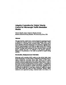
The objective of the FAC is to tune the scaling factors in the FLC, according to the comparison between a reference signal and the system output. So, the adaptation algorithm defines the output linguistic values for each rule of the controller rule base table, based on a desired trajectory. Simulation results have been obtained for the test where a repetitive step change in the load torque (from 0 to 700 and then back to500) was applied during the movement. In Fig. 7, the transient response of the two AFC schemes is relatively short and robust compared with the PI controller, simple FLC. The efficiency of the FAC controllers is evaluated and compared using a two different speed profiles as the command input. A repetitive step change in the load inertia (from Jn to 3Jn and back to Jn) was applied during the movement. Fig. 8 shows that the systems output tracks very closely the reference model in spite of the disturbance. The proposed adaptive fuzzy controller is simple does not require complex mathematical operations. The performance criteria used shows that there is improvement in set point tracking as the ISE is reduced with two FAC schemes than the PI and simple FLC. It is illustrated in table 6. From the results obtained in our simulation it can concluded that the FAC was able to track set point change and reject the uncertainties resulting from external disturbances and plant model mismatches. The responses were somehow sluggish in the faces of external disturbances but give no oscillatory behaviors. For PI controller, the performance deteriorated for set point changes and under the influence of external disturbances. A Modified approach to FAC using output scaling factor has been studied for the control of a vector controlled PMSM drive. In the proposed scheme, the adaptation mechanism produces a compensation signal, which is added to the output signal of the direct fuzzy controller to force the system to behave like the model. The simulation results have confirmed the efficiency of the proposed fuzzy adaptive scheme for changing load torque. 96
©2010 International Journal of Computer Applications (0975 – 8887) Volume 1 – No. 11 1000
900 Reference Input PI
800
800
700
700
600
600
Speed Output
Speed Output
Reference Input PI(1:17941,1:2)(:,2)
900
500 400
500 400
300 300
200 200
100 100
0 0
-100
0
2000
4000
6000
8000
10000 Time
12000
14000
16000
0
5000
15000
(a) PI
(a) PI 900
1000
FLC Reference Input
800
Reference Input FLC
900
700
800
600
700
500
600
Speed Output
Speed Output
10000 Time
18000
400 300
500 400 300
200
200
100 100
0 0
-100
0
2000
4000
6000
8000
10000 Time
12000
14000
16000
0
5000
10000
15000
Time
18000
(b) FLC
(b) FLC 900
FAC Reference Input
1000 800
FAC Reference Input
900
700
800 600
Speed Output RPM
Speed Output
700 600 500 400
400 300 200
300
100
200
0
100 0
500
-100
0
5000
10000
15000
Time seconds
0
1000
2000
3000
4000
5000 Time
6000
7000
8000
9000
10000
(c) FLC Tuned using Input Scaling Factor
(c) FLC Tuned using Input Scaling Factor 900
1000 Modiefied FAC Reference Input
800
Reference Input Modified FAC
900
700
800
600
Speed Output
Speed Output RPM
700 500 400 300
600 500 400
200
300
100
200
0 -100
100 0
5000
10000
15000
Time sec
0
0
5000
10000
15000
Time
(d) FLC Tuned using Output Scaling factor Figure 8. Step Response of Load Torque.
(d) FLC Tuned using Output Scaling factor Figure 9. Step Response for repetitive step change in load inertia. 97
©2010 International Journal of Computer Applications (0975 – 8887) Volume 1 – No. 11 The presented FAC has proved to be very efficient when applied in motion control. The improved algorithm demands little, although reasonable, modifications in the original mechanism based on the fuzzy inverse model approach. At each sample instant the FAC will affect only the active rules, taking into account its weight in the control signal.
[4] J.L. Silva Neto, and H. Le Huy 1998 An improvement fuzzy learning algorithm for motion control applications, Proc. of the IEE, Vol. 1, pp. 1-5.
Table 6 Comparison of Controller Performance
[6] D.S. Reay, and M.W. Dunniganu 1997 Learning issues in model reference based fuzzy control, Proc. of the IEE Control Theory Application, Vol. 144, No. 6.
Controller
Set Point
PI
Given 700
FLC
Change in Set Point from 0-700500 Given 700
AFC using Input Scaling Factors
AFC using Output Scaling Factor
Change in Set Point from 0-700500 Given 700 Change in Set Point from 0-700500 Given 700 Change in Set Point from 0-700500
OV %
RT sec
ST sec
ISE
5.2
33
325
1.19
15.7
36
332
1.26
IAE
[5] M. Kadjoudj, R. Abdessemed, M.E. Benbouzid, and C. Ghennai 2000 Current control of PMSM fed by two and three levels VSI, in Proc. of EPE/PEMC, Tuke (Slovakia), Vol. 7,pp. 69-74.
2.511
[7] M.A Henson, and D.E. Seborg 1990 Input- Output linearization of general non-linear processes, AIChE Journal, Vol.36, pp.1753-1757.
3.116
[8] W. A. Kwong, and K. Passino 1994 Fuzzy learning systems for aircraft control law reconfiguration, in Proc. IEEE Int. Symp. Intell. Contr., Columbus, OH, Aug. 16–18, pp. 333–338. [9] W. A. Kwong, K. M. Passino, E. G. Lauknonen, and S. Yurkovich, 1995 Expert supervision of fuzzy learning systems for fault tolerant aircraft control, Proc. IEEE, Spec. Issue Fuzzy Logic Engg. Application, vol. 83, pp. 466–483.
2.6
31
220
1.13
2.369
9.3
32
235
1.16
2.956
[10] D.S. Reay, and M.W. Dunniganu 1997 Learning issues in model reference based fuzzy control, Proc. of the IEE Control Theory Application, Vol. 144, No. 6. [11] J.T. Spooner, R. Ordonez and K.M. Passino1996 Stable direct adaptive control of a class of discrete time non-linear systems, Proc. of the 13th IFAC world congress, San Francisco, pp. 343-348.
0.4
30
135
1.13
2.342
0.7
30
155
1.19
2.931
[12] N. J. Patil, R.H. Chile and L. M. Waghmare 2007 Model Reference Adaptive Fuzzy Controller, Proc. of the International Conference on Information and Communication Technology in Electrical Sciences, ICTES 2007, Vol. 1, pp.100-104. [13] K. Pal, R.K.Mudi and N.R.Pal 2002 A new scheme for fuzzy rule-based system identification and its application to self-tuning fuzzy controllers, IEEE trans. on Systems Man and Cybernetics vol.32, pp. 470-482.
0.4
30
133
1.13
2.375
[14] P. Pillay and R. Krishnan 1987 Application characteristics of PM Synchronous and BLDC servo drives, Conf. Record, IEEE IAS Annual meeting, Atlanta, pp. 380-390.
0.7
31
152
1.16
2.610
[15] Seema Chopra, R. Mitra and Vijay Kumar 2008 Auto Tuning of Fuzzy PI Type Controller Using Fuzzy Logic , International Journal of Computational Cognitin, Vol. 6, No. 1, pp 12-18.
7. REFERENCES [1] M. Kadjoudj, M.E. Benbouzid, C. Ghennai, and D. Diallo, 2004 A Robust hybrid current control for PMSM drives, IEEE trans. on Energy Conv. Vol. 19, No. 1, pp. 109-115. [2] J.M. Mendel, 1995 Fuzzy logic systems for engineering, A tutorial, Proc. of the IEEE, Vol. 83 No. 3, pp. 345-377. [3] L. Zhen, and L. Xu, 2000 Fuzzy learning enhanced speed control of an indirect field oriented control induction machine drive, IEEE Trans. on Control Systems Technology, Vol. 8, No. 2, pp. 270-278.
[16] Seema Chopra, R. Mitra and Vijay Kumar 2006 Analysis of Fuzzy PI and PD type controllers using subtractive clustering, International Journal on Computational Cognition, Vol 4, No. 2, pp 30-34. [17] Mohamed Kadjoudj1, Noureddine Golea1, Mohamed El Hachemi Benbouzid 2007, Fuzzy Rule – Based Model Reference Adaptive Control for PMSM Drives, Serbian Journal of Electrical Engineering Vol. 4, No. 1, 13-22. [18] Seema Chopra, R. Mitra and Vijay Kumar 2005 Fuzzy Controller: Choosing an Appropriate and Smallest Rule Set , International Journal on Computational Cognition, Vol 2, No. 4, pp 73-79.
98