SNR gain vs. cyclic delay for 2TX-antenna CDD systems at a BER of 10â4 ... [1] V. Tarokh, N. Seshadri, and A. R. Calderbank, âSpace-time codes for high data ...
Comparison of Space-Time Block Coding and Cyclic Delay Diversity for a Broadband Mobile Radio Air Interface Armin Dammann, Ronald Raulefs
Gunther Auer, Gerhard Bauch
German Aerospace Center (DLR) Institute of Communications and Navigation P.O.Box 1116 82234 Oberpfaffenhofen, Germany Email: {Armin.Dammann, Ronald.Raulefs}@DLR.de
DoCoMo Communications Laboratories Europe GmbH Landsberger Straße 312 80687 Munich, Germany
Abstract— In this paper, we apply two different types of space-time block codes (STBC) in the downlink of a broadband mobile radio air interface based on MCCDMA, which is a promising candidate for a 4th generation mobile radio system. The first type are ”STBCs from orthogonal designs”. For 2 TX-antennas, this is the wellknown ”Alamouti”-scheme. These STBCs are compared to a different type, called cyclic delay diversity (CDD), which can be considered as STBC. Compared to STBCs of the first type, CDD can be applied with an arbitrary number of TX-antennas. Furthermore, no modification at the receiver is necessary, if the number of TX-antennas is changed. Simulations show the bit error performance of different TX/RX-antenna configurations for both STBC approaches, where, in fact, CDD performs mostly worse than STBCs from orthogonal designs, but with explicit complexity advantages.
I. I NTRODUCTION Future mobile radio systems are expected to provide and serve a wide range of applications, which inherently enforces high data rates. Currently, data rates of up to 100 Mbps and a bandwidth allocation of about 100 MHz are under discussion for mobile communication systems of the 4th generation. Multicarrier (MC) based systems, are approved candidates for providing the demanded data rates in a wide range of multipath fading environments with reasonable complexity. For further increase of the capacity and performance of such communication systems, multiple antenna (MIMO) techniques at both receiver and transmitter can be applied. One approach is the usage of antenna arrays with beamforming, often referred to as smart antennas. Space-time coding [1], which is a further MIMO approach, uses sets of independent and often omnidirectional antennas, why this method — in contradiction to smart antennas — is sometimes called dumb antennas [2]. In [3] Wittneben proposed a low complex TX-antenna delay diversity scheme, which was modified in [4] for the usage with OFDM systems by exploiting the properties of the discrete Fourier transform.
In this paper we compare two ’space-time block codes (STBC) from orthogonal designs’ [5] — including the well-known Alamouti-scheme — and cyclic delay diversity (CDD) as MIMO techniques for a mobile radio air interface based on MC-CDMA [6]. In the following sections, we first introduce the STBCs under investigation. Then, the simulation system layout and the channel model is described. Finally, simulation results show the performance of both STBCs from orthogonal designs and CDD in comparison to a single-TX-antenna reference system.
II. S PACE -T IME B LOCK C ODES U NDER I NVESTIGATION A. Space-Time Block Codes From Orthogonal Designs In this section, we focus on STBCs from orthogonal designs [5]. These codes are based on the theory of (generalized) orthogonal designs for both real and complex valued signal constellations. The complex valued STBCs, can be described by a matrix ← space → ··· b0,S−1 ↑ .. .. B = time , . . ↓ bn−1,0 · · · bn−1,S−1
b0,0 .. .
(1)
where n and S is the STBC length and the number of TX-antennas respectively. The STBCs, used for simulations, are the well-known Alamouti code [7] � B=
x0 −x∗1
x1 x∗0
� (2)
and a STBC with length n = 8 and dimension k = 4 for 3 TX-antennas1 [8] with x0 x1 x2 −x1 x0 −x3 −x2 x3 x0 −x3 −x2 x1 . B= ∗ (3) ∗ x∗2 x0∗ x1∗ ∗ −x x0 −x3 1 −x∗2 x∗3 x∗0 −x∗3 −x∗2 x∗1 If the rows of a STBC-matrix B exclusively contains either information symbols ±xi or their conjugate complex (±x∗i ), the relationship between the information symbols and the received signal y(r) at RX-antenna r can be described by a matrix multiplication y(r) = H(r) · x + n(r) ,
(4)
where the elements of the n×k matrix H(r) are complex valued fading coefficients h(s,r) , which describe the fading from TX-antenna s to RX-antenna r and n(r) describes complex valued white Gaussian noise at RXantenna r. The vector x = (x0 . . . xk−1 )T contains the information symbols of the STBC codeword. Hence for the 3x4x8-scheme we can write (r) y0 y (r) 1 (r) y2 (r) y (r) 3 y = y (r)∗ = 4 (r)∗ y5 (r)∗ y6 (r)∗ y7 (0,r) h h(1,r) h(2,r) 0 h(1,r) −h(0,r) 0 −h(2,r) (2,r) (0,r) h 0 −h h(1,r) 0 h(2,r) −h(1,r) −h(0,r) · = (0,r)∗ h(1,r)∗ h(2,r)∗ 0 h (2,r)∗ h(1,r)∗ −h(0,r)∗ 0 −h h(2,r)∗ 0 −h(0,r)∗ h(1,r)∗ 0
h(3,r)∗
·
−h(1,r)∗ −h(0,r)∗ (r) n0 n(r) 1 (r) n2 x0 (r) x1 n3 + (r)∗ . (5) x2 n4 (r)∗ x3 n5 (r)∗ n6 (r)∗ n7
1 we
refer to it as ”3x4x8”-code
The respective assignment for the Alamouti-STBC is ! (r) y0 (r) y = = (r)∗ y1 ! � (0,r) � � � (r) h h(1,r) n0 x0 = + · (r)∗ x1 h(1,r)∗ −h(0,r)∗ n1 (6) Note, that y(r) is an auxiliary construct, since it is (r) obtained from the received complex values yi or their (r)∗ conjugate complex yi at the receiver. At the receiver, the vector y(r) is multiplied from left by the Hermitean of matrix H(r) . Assuming a quasi static channel fading, i.e. the fading coefficients remain constant for the duration of a STBC codeword, we obtain the (weighted) STBC information symbols x ˆ = H(r)H · y(r) = H(r)H · H(r) x + H(r)H · n (7) � P1 (i,r) 2 |h | , Alamouti i=0 P2 = H(r)H · n + x · 2 · i=0 |h(i,r) |2 , 3x4x8, corrupted by noise. For STBCs from orthogonal designs, MIMO channel estimation at the receiver is mandatory, i.e. h(s,r) , s = 0 . . . S − 1, r = 0 . . . R − 1 must be estimated. Since the correlation of the subcarrier fading coefficients in time direction is decreasing with increasing Doppler spread — i.e. the quasi stationarity assumption of the fading is incrementally violated — the performance of this STBC class will suffer from higher Doppler frequencies. B. Cyclic Delay Diversity Subsequently, we briefly introduce the application of cyclic delay diversity (CDD) to OFDM systems as described in detail in [4], [9]. In [10] it is shown that CDD can be viewed as space-time block coding method. Fig. 1 shows the block diagram of a S-antenna CDD OFDM transmitter front-end. The OFDM modulated signal is transmitted over S antennas, whereas the particular signals only differ in an antenna specific cyclic shift. The signal after OFDM modulation is normalized such that the average transmitted power is independent of the number of TX-antennas S. After cyclic shifting, a cyclic prefix is inserted to avoid intersymbol interference and maintain subcarrier orthogonality for multipath channels. δcy s , s = 1, . . . , S − 1, denote cyclic shifts of the OFDM symbol in the time domain. Without loss of generality, we can set δcy 0 = 0. A cyclic delay δcy s , applied at TX-antenna s, corresponds to the multiplication of a phase factor −j N 2π
φ` = e
FFT
δcy s ·`
,
(8)
whose phase is linearly increasing with the subcarrier index `. This phase shift and the normalization factor
Source
Interleaver
Encoder
Mapper
M U . X M
ΣU
Spreader
1 K
1
+TG
Interleaver
X
M
Σ
Spreader
M
c(1)
(L)
dM
+
spreader
c(L)
converter
1 Nc
L
(Kmax)
+
spreader
c(L)
(K
-L+1)
d M max
spreader
c(1)
)
+
1
d M max
spreader
Fig. 3.
MC-CDMA part of a 1-TX transmitter
c(L)
1
1 L
...
(K
(1)
d (Ml )
...
c
d1
1
spreader
...
(Kmax -L+1)
d1
1
...
user group Q
spreader
...
The simulation layout can be divided in an user specific coding/modulation part and a MC-CDMA part. Fig. 2 shows the user specific part. After encoding of the user information bits by a rate 1/2 convolutional encoder, the codebits are interleaved randomly. The resulting bit stream is assigned to symbols of a 4-QAM constellation
(1)
dM
1
L
...
A. Simulation Layout
c(L)
...
III. S YSTEM OVERVIEW
{ {
+
spreader
...
is observed. Hence, CDD can be described as a transformation of a multi-TX-antenna system operating in (s,r) an MIMO channel environment with CTFs h` into a single TX-antenna system with a superposition channel (r) described by the CTF h` . Note, that CDD does not necessarily need MIMO/MISO channel estimation. If SIMO/SISO channel estimation is used, it must be kept in mind that the algorithms have to cope with an increased observable maximum channel delay spread of τ˜max = τmax + maxs [δcy s ]. Due to the construction of CDD, however, the OFDM guard interval length has to cover only the maximum component-channel delay spread τmax (not τ˜max ). A further advantage of CDD compared to STBCs from orthogonal designs is the flexibility in the choice of the number of TX-antennas S. In general, it is also possible to implement CDD at the receiver side (see e.g. [4]). However, the RX-antenna combining using CDD is not optimal unlike maximum ratio combining.
d (Ml )
OFDM + cyclic extension
user group 1
(s,r)
where h` denotes the complex valued fading coefficient at subcarrier ` from TX-antenna s to RX-antenna r. At RX-antenna r, the superposition of S modified CTFs S−1 1 X (s,r) (r) h` = √ · h` · φ` (10) S s=0
{ {
d1
...
(9)
(L)
d1
...
˜ (s,r) = h(s,r) · φ` , h ` `
c(1)
...
can be formally assigned to the channel, which results in a modified channel transfer function (CTF)
{ {
1
spreader
...
Front-end of a CDD OFDM transmitter
(1)
d1
...
Fig. 1.
cyclic extension
. . .( l )
L
Nc
Nc
OFDM + cyclic extension
δcy S-1
Source
Symbol Mapper
frequency interleaver
. . .
Nc
Encoder
d1( l )
. . Codebit Symbol Channel Fig. 2. User specific data encoding and signal processing . Encoder Interleaver Mapper 1-st data symbol per user
δcy 1
M-th data symbol per user
S
cyclic extension
1-st data symbol per user
1
cyclic extension
M-th data symbol per user
. . .
OFDM
Source δcy S-1
Codebit Interleaver
Channel
serial-to-parallel converter
extension
serial-to-parallel converter
cyclic δcy 1
serial-to-parallel converter
OFDM
cyclic extension
serial-to-parallel converter
1
STBC
cyclic extension
serial-to-parallel serial-to-parallel converter
K
S
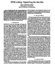
using Gray mapping. These user symbols are serial-toparallel converted and fed into the MC-CDMA part, which is depicted in Fig.3. Here, the data symbols are spread by a user-specific Walsh-Hadamard (WH) sequence. The resulting chips are superposed by the spreading results (chips) of other (up to L − 1) active users. and mapped to M ·L subcarriers of a MC-system. The same signal processing is done for up to L · (Q − 1) other users. The total number of possible users in the system is L · Q and the total number of used subcarriers is L · Q · M . As shown in Fig. 3, the L chips of a WH sequence are distributed over the whole bandwidth by a blockinterleaver. The L × M · Q interleaver matrix is read in column wise and read out row by row. The following STBC entity provides the TX-antenna specific subcarrier symbols, which are finally OFDM modulated and transmitted. The signal for each TX-antenna is normalized to the number of TX-antennas, which keeps the average transmission power constant with respect to
0
FFT-length # subcarriers Bandwidth Subcarrier spacing OFDM symbol duration Sampling time Spreading code Spreading length User symbols per OFDM symbol Active users User groups Guard interval length Modulation Detection
NFFT Nc B ∆fsc TOFDM Ts
L M KQ Q
Coding
Channel fDmax
Doppler spread Channel estimation
1024 768 100 MHz B/Nc = 130.2 kHz 1/∆fsc = 7.68 µs TOFDM /NFFT = 7.5 ns Walsh-Hadamard 16 16 1,16 3 22 samples (≡ 165 ns) 4-QAM MMSE (KQ = 16), MRC (KQ = 1) (133,171) convolutional code, rate 1/2, MLViterbi decoding 12-tap, exp. power decay, τmax = 165 ns 20 Hz (≡ 6 m/s @ 1 GHz) perfect
the number of TX-antennas. In case of STBCs from orthogonal designs, the STBC entity is determined by the STBC matrix B, described in Sec. II-A. Space-time block coding is applied to each (data) subcarrier, e.g. one 3x4x8-STBC codeword spans 8 OFDM symbols. For CDD, the STBC block inserts TX-antenna and subcarrier specific phase shifts as explained in Sec. II-B. Table I shows the main parameters of the simulation system. B. Channel For simulations, a MIMO channel model for S TXantennas and R RX-antennas is used. The S · R statistically independent component channels describe the signal transmission from each TX-antenna s, 0, . . . , S − 1 to each RX-antenna r, 0, . . . , R − 1. Each component channel is determined by a 12-tap delay line model with statistically independent Rayleigh fading characteristics for each tap. Fig. 4 shows the average relative power delay spectrum for the component channels. The maximum component channel delay spread is τmax = 22 samples (≡ 165 ns). The Doppler characteristic of each tap is of Jakes form with a maximum Doppler spread of 20 Hz, which is equivalent to a mobile velocity of 6 m/s at a carrier frequency of 1 GHz. IV. S IMULATION R ESULTS Fig. 5 shows the bit error performance vs. the signalto-noise ratio (SNR) for CDD systems compared to a single-TX-antenna system for different antenna configurations. The TX-antenna specific cyclic delays are
relative average tap power [dB]
TABLE I M AIN S YSTEM PARAMETERS
-2 -4 -6 -8 -10 -12
Fig. 4.
0
2
4
6
8 10 12 14 delay [samples]
16
18
20
22
Power-delay spectrum of the component channels
chosen according to δcy s = s · δcy ,
s = 0, . . . , S − 1,
(11)
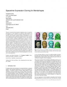
where the cyclic delay increment δcy = 40 samples. It can be seen that SNR gains of up to 2 dB and 1.3 dB are achieved for 1-RX- respectively 2-RXreceivers. Similarly, Fig. 6 compares the BER of the Alamouti- and 3x4x8-scheme. For comparison, the 3TX CDD results are plotted again. Both figures show the BER of fully loaded systems, using MMSE detection (dashed lines), and the respective single user bound, using MRC detection at the receiver (solid lines) for one resp. two RX-antennas. Comparing 3-TX CDD and Alamouti-STBC, one can observe that 3-TX CDD slightly outperforms the Alamouti-scheme for the single user bounds. However, for fully loaded systems using MMSE detection, CDD performs worse. Generally, it can be stated, that STBCs from orthogonal designs transfer a multipath fading scenario towards an AWGN channel, whereas the application of CDD reduces the correlations between fading coefficients in frequency direction. The SNR is specified as Eb /N0 at one TX-antenna, i.e. the average received signal power is not normalized to the number of RX-antennas R. As mentioned in Sec. III-A, the average transmission power does not depend on the number of TX-antennas. If more than 1 RX-antenna is used, the signals of different RX-antenna branches are optimally combined for each subcarrier by means of maximum ratio combining. The achievable SNR gains at a BER of 10−4 vs. the cyclic delay for 2-TX CDD compared to the respective single-TX-antenna systems can be seen from Fig. 7. First of all, it is remarkable that the graphs are oscillating for low cyclic delays. This behavior results from the regular structure of the power delay spectrum of the component channel. For even valued cyclic delays lower than 22 samples, i.e. δcy = 2, 4, 6, . . . , 22, channel propagation paths from different TX-antennas are overlapping, which causes a reduction in the overall number of observable propagation paths and yields a loss in
2.0
-1
1TX/1RX, MMSE 1TX/1RX, MRC 1TX/2RX, MMSE 1TX/2RX, MRC CDD 2TX/1RX, MMSE CDD 2TX/1RX, MRC CDD 2TX/2RX, MMSE CDD 2TX/2RX, MRC CDD 3TX/1RX, MMSE CDD 3TX/1RX, MRC CDD 3TX/2RX, MMSE CDD 3TX/2RX, MRC
-2
10
-3
BER
10
-4
10
-6
1.0
0.5
-5
10
10 -1
1.5
SNR-gain [dB]
10
CDD 2TX/1RX, MMSE CDD 2TX/1RX, MRC CDD 2TX/2RX, MMSE CDD 2TX/2RX, MRC
0
1
2
3
4
5
6
7
8
9
10
11
12
13
14
0.0
Eb/N0 [dB]
Fig. 5. Bit error performance of single TX-antenna and 2 TX-antenna CDD systems -1
10
CDD 3TX/1RX, MMSE CDD 3TX/1RX, MRC CDD 3TX/2RX, MMSE CDD 3TX/2RX, MRC Alamouti 1RX, MMSE Alamouti 1RX, MRC Alamouti 2RX, MMSE Alamouti 2RX, MRC 3x4x8, 1RX, MMSE 3x4x8, 1RX, MRC 3x4x8, 2RX, MMSE 3x4x8, 2RX, MRC
-2
10
-3
BER
10
5
10
15
20
25
cyclic delay δcy [samples]
30
35
40
Fig. 7. SNR gain vs. cyclic delay for 2TX-antenna CDD systems at a BER of 10−4 compared to single-TX-antenna systems
•
• •
-4
10
0
•
No necessity of MIMO channel estimation, therefore lower receiver complexity. The number of TX-antennas is arbitrary. Low implementation complexity, due to simple cyclic shifts in the time domain. No quasi stationarity fading assumptions.
-5
10
-6
10 -1
R EFERENCES 0
1
2
3
4
5
6
7
8
9
10
11
12
Eb/N0 [dB]
Fig. 6. Bit error performance of Alamouti and 3x4x8 STBC systems
diversity. E.g. for a 2-TX antenna system with δcy = 1, 24 different paths are observable, whereas for δcy = 2 only 13 different paths are obtained. For higher cyclic delays, the achievable gains reach a saturation. Note, that STBCs from orthogonal designs with quadratic encoding matrix does only exist for 2 TXantennas. Therefore codes with more than 2 TXantennas yield a loss in the spectral efficiency (compare e.g. Eqs. (2) and (3)). V. C ONCLUSIONS In this paper we compared two different space-time block coding techniques. For the class of STBCs from orthogonal designs, we have exemplarily chosen the well-known Alamouti-scheme and a 3 TX antenna rate 1/2 STBC. The competing approach was a standard compatible TX-antenna diversity technique called cyclic delay diversity (CDD). For comparison, a single-TXantenna system was implemented. Simulation results have shown that STBCs from orthogonal designs outperform CDD for most of the simulation scenarios. On the other hand, there are several advantages of CDD compared to STBCs from orthogonal designs: • Standard compatibility, i.e. CDD can be applied without changing the receiver.
[1] V. Tarokh, N. Seshadri, and A. R. Calderbank, “Space-time codes for high data rate wireless communication: Performance criterion and code construction,” IEEE Transactions on Information Theory, vol. 44, no. 2, pp. 744–764, March 1998. [2] G. Bauch and J. Hagenauer, “Smart versus dumb antennas — capacities and FEC performance,” IEEE Communications Letters, vol. 6, no. 2, pp. 55–57, February 2002. [3] A. Wittneben, “A new bandwidth efficient transmit antenna modulation diversity scheme for linear digital modulation,” in Proceedings IEEE International Conference on Communications (ICC 1993), May 1993, pp. 1630–1634. [4] A. Dammann and S. Kaiser, “Standard conformable antenna diversity techniques for OFDM and its application to the DVBT system,” in Proceedings IEEE Global Telecommunications Conference (GLOBECOM 2001), November 2001, pp. 3100– 3105. [5] V. Tarokh, H. Jafarkhani, and A. R. Calderbank, “Space-time block codes from orthogonal designs,” IEEE Transactions on Information Theory, vol. 45, no. 5, pp. 1456–1467, July 1999. [6] S. Kaiser, “Multi-carrier CDMA mobile radio systems - analysis and optimization of detection, decoding, and channel estimation,” Ph.D. dissertation, University of Kaiserslautern, Germany, 1998, VDI-Verlag, Fortschrittberichte VDI, Series 10, No. 531, ISBN 3-18-353110-0. [7] S. M. Alamouti, “A simple transmit diversity technique for wireless communications,” IEEE Journal on Selected Areas in Communications, vol. 16, no. 8, pp. 1451–1458, October 1998. [8] G. Bauch, “Turbo-Entzerrung und Sendeantennendiversit¨at mit Space-Time Codes im Mobilfunk,” Ph.D. dissertation, Munich University of Technology, 2001, in German. [9] A. Dammann and S. Kaiser, “Transmit/receive antenna diversity techniques for OFDM systems,” European Transactions on Telecommunications, vol. 13, no. 5, pp. 531–538, September/October 2002. [10] A. Dammann, P. Lusina, and M. Bossert, “On the equivalence of space-time block coding with multipath propagation and/or cyclic delay diversity in OFDM,” in Proceedings European Wireless 2002, Florence, Italy, vol. 2, February 2002, pp. 847– 851.