[1] and the ISO Transport Protocol class 4 (TP4) [2] ap- ... services up to the network level, TCP and TP4 remain .... a connectionless network service. The service ...
1
Comparison of TP4, TCP and XTP - Part 1: Connection Management Mechanisms (*) Yves Baguette (**) , André Danthine Université de Liège, Service de Systèmes et Automatique, Institut d'Electricité Montefiore B28, B-4000 Liège (Sart Tilman), Belgium
Abstract. This paper is the first part of a comparative study of the transport mechanisms of three protocols: ISO TP4, XTP and, to a lesser extent, DARPA TCP. This first part focuses exclusively on the connection management (i.e. connection set-up and release) mechanisms. The mechanisms used during the phase of data transfer over a connection will be analysed in the companion paper. The goal of the comparison of the connection management mechanisms is to determine the suitability of each of the three protocols assuming that they operate in HSLANs environments characterized by high performance but also, possibly, by a wide range of application requirements as regards the types of communications to provide. This paper takes account of the very last Revision 3.6 of XTP and of the upgraded version of the ISO Transport Protocol which has been circulated for ballot as Draft International Standard (DIS) 8073. Keywords. Transport Protocols, High Performance, High-Speed LANs, TP4, TCP, XTP, OSI 95, CIO.
1 . Introduction The DARPA Transmission Control Protocol (TCP) [1] and the ISO Transport Protocol class 4 (TP4) [2] appeared while the common communication infrastructure was still made of switched lines, leased lines and also packet switching WANs based on the telephone technology and on low-performance computer switching nodes. The medium bandwidth with its rather high error rate, the node buffer space and the node processing power were then the major critical resources. The design of TCP and TP4 was conditioned by the concern of obtaining an error-free service in such environments. Even though the network technology is now considerably different in the LANs with their connectionless services up to the network level, TCP and TP4 remain the two currently most used connection-oriented transport protocols in these LANs environments. Today, at least in the LANs, the existence of appreciable throughputs is generally recognized. However, in order to keep high throughputs at the transport service interface, the processing delays and latencies in the transport layer have to be strictly controlled. Besides the evolution towards more and more efficient network infrastructures, there is an evolution towards the diversification of the application needs as regards the
communications over the networks, due in particular to the advent of distributed systems. Furthermore, the advent of multimedia services is offering new possibilities to the users but are also requesting new services from the transport layer. Since the transport layer is a “key” layer which is intended to serve as a junction between the application needs and the possibilities offered by the networks, the aforementioned evolutions suggest that the design criteria adopted for the transport protocols in the early '80s should be revisited. A protocol always implies several mechanisms to perform the set of requested functions, a syntax which describes the Protocol Data Unit (PDU) format and at last an implementation. It is claimed by some people that the implementation is very often responsible for poor performance. It is true that a poor implementation gives rise to poor performance, but even good implementations are not able to correct the influence of poorly designed mechanisms and to cope in the most efficient way with badly designed PDU formats. Among the new protocols at the transport level, the Xpress Transfer Protocol (XTP) [3] represents a novel approach to protocol design. In reality, XTP is not just a transport protocol. XTP is called a transfer protocol because it has not only a transport part but also, with a view to attempting to improve the congestion control, a
_______________________________________ (*) This paper results from work that was carried out within the framework of the ESPRIT II Project "OSI 95" (Project no. 5341) and more recently of the RACE Project "CIO" (Project no. 2060). (**) Research assistant of the Belgian National Fund for Scientific Research (F.N.R.S.). VOL. 3 - N. 5 SEPT.-OCT. 1992
###
2
Yves Baguette - André Danthine
routing part which belongs to the OSI layer 3. XTP has been designed within the framework of the Protocol Engine (PE) project. This project is currently developing circuits that implement protocols located in the OSI layers 3 and 4 and that also implement the host and data link level interfaces. The design choices in XTP aim at meeting the performance goals [4]. The subject of this paper and of the companion paper [5] is a thorough comparison of the transport mechanisms of TP4, XTP and, to a lesser extend, TCP. The comparative analysis of these three protocols will focus on their mechanisms exclusively, and especially from a qualitative rather than quantitative point of view, so that all the aspects regarding the syntax or the implementation will simply be left apart. The mechanisms of TP4 will be examined in detail to highlight all their limitations and drawbacks with respect to their applicability in the high-bandwidth low-error-rate area. An in-depth analysis of the transport mechanisms of XTP will be carried out in parallel in order to clearly identify how it contributes to the improvement of the past situation. In other words, every major transport mechanism of XTP, in addition to being described, will be compared with the equivalent one of TP4 (if it exists!). It means that the mechanisms of TP4 will be utilized as points of reference for the study of the transport mechanisms of XTP. Whenever it turns out that they bring further information into the discussion, the mechanisms supplied in TCP will also be described and compared with those of TP4 and/or XTP. This paper is entirely dedicated to the connection management mechanisms whereas its companion paper [5] is dedicated to the mechanisms used during the phase of data transfer over a connection. The design of XTP, which has been a 5-year process so far, has already led to the issue of roughly ten distinct revisions of the protocol. Since the Revision 3.4 [6], there has been an effort to stabilize the design, with increasing periods between the successive revisions. Our work in this paper will be based on the very last Revision 3.6 [7], issued on January 1992. Moreover, our comparative study will take account of the upgraded version of the ISO Transport Protocol which has been circulated for ballot as DIS 8073 [8]. This upgraded version is an attempt to adapt the ISO Transport Protocol to the new high-speed environments. It offers selective acknowledgements and allows the sending side to request immediate acknowledgements. This upgraded version has of course the constraint of preserving the interoperability with today's standard. In section 2 of this paper, the basis for the comparative study is defined. Then, after some generalities about connection management in section 3, the connection setup and release mechanisms of TP4, TCP and XTP are compared in section 4, with conclusions in section 5.
2 . Basis for the comparative study
2 . 1 . TP4 in the LANs Originally, the possibility of making the standard ISO TP4 [2] operate above a connectionless network service was not specified in the norms of ISO. An addendum [9] was issued later on to deal with TP4 operation above a connectionless network service. The service assumed from the network layer is then the standard ISO ConnectionLess Network Service (CLNS) [10] provided by the standard ISO ConnectionLess Network Protocol (CLNP) [11]. CLNP is an internet protocol which offers the standard ISO CLNS by relying on the standard ISO connectionless SubNetwork Service. CO Transport Service
4
TP4
Transport
Internet
3 SubNetwork LLC
2 MAC
CL Network Service CLNP or proper subset CL SubNetwork Service SNDCFs (=> no protocol) LLC Type 1 Service LLC Type 1 Protocol MAC Service MAC Protocol
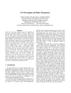
Fig. 2-1 ISO protocol stack for layers 2 to 4 in LANs environments
In LANs environments, this standard ISO connectionless SubNetwork Service can be provided by applying SubNetwork Dependent Convergence Functions (SNDCFs) [12] directly above the standard connectionless LLC Type 1 Service [13], as illustrated in Figure 2-1. The presence of a LLC protocol is mandatory in the ISO protocol suite. The SNDCFs are simply local mapping functions. No protocol is required in the subnetwork sublayer to “fill the gap” between the LLC Type 1 Service and the SubNetwork Service. Throughout this paper, the term ‘router’ will refer to an interconnecting gateway that performs a relay function in the internet sublayer. In case of interconnected LANs implying routers, the full CLNP protocol (or at least a proper subset of CLNP which is referred to as the NonSegmenting Protocol Subset) must be used. In case of an isolated LAN or of a set of LANs interconnected only by bridges that perform a relay function at the MAC level, the full CLNP protocol may be replaced by another proper subset, the Inactive Network Layer Protocol Subset, which is nothing else than a null-function subset. 2 . 2 . TCP in the LANs
Here we are interested in making TP4, TCP and XTP operate in LANs environments. We assume therefore that the whole network either is an isolated LAN or is made up of a set of interconnected LANs. ###
In the DARPA (or DoD) protocol stack, the transport-level TCP [1] is associated with the underlying
ETT
Comparison of TP4, TCP and XTP - Part 1: Connection Management Mechanisms
Internet Protocol (IP) [14] and Internet Control Message Protocol (ICMP) [15]. Normally, TCP cannot run without IP. That is why the normal way to proceed is to systematically install the whole TCP/IP combination in all systems, irrespective of the presence of routers between LANs in the network.
4
follows the guidelines established in [17-18], which use the non-OSI SubNetwork Access Protocol (SNAP) for identifying public and/or private protocols that want to have access to the LLC Type 1 Service. Figure 2-3 illustrates the LLC encapsulation of IP packets as currently specified. MAC Header
LLC Header(3)
SNAP Header(5)
DSAP(1) SSAP(1) control(1) org code(3) Internet
170
2 MAC
type(2)
IP & ICMP
3 LLC
IP packet
TCP
Transport
SubNetwork
3
170
3
0
ox0800
Empty sublayer Empty sublayer MAC Service MAC Protocol (Ethernet-DIX)
(a)
170 (decimal) is the reserved LSAP address attributed to the SNAP LSAP, i.e. the LSAP on which public and/or private protocols can be multiplexed by means of SNAP, 3 (decimal) is the type code for an Unnumbered Information LPDU, 0 is the organization code assigned to Xerox Corporation, ox0800 (hexadecimal) is the type code (the same as for Ethernet-DIX) to identify IP as the protocol occupying the upper layer Fig. 2-3 LLC encapsulation of IP packets by using SNAP
4
TCP
Transport
Internet
IP & ICMP
3 SubNetwork LLC
2 MAC
SNAP Protocol LLC Type 1 Service LLC Type 1 Protocol MAC Service MAC Protocol (ISO 8802-x series or FDDI)
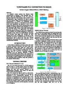
(b) Fig. 2-2 DARPA protocol stack for layers 2 to 4 in LANs environments when TCP/IP is used (a) over an Ethernet-DIX LAN or (b) over an IEEE 802 or FDDI LAN
The two DARPA protocol stacks are shown in Figure 2-2. Figure 2-2(a) is related to the Ethernet-DIX de facto standard (from Digital, Intel and Xerox) [16], in which case TCP/IP is installed directly above the connectionless MAC service without intermediate LLC protocol. Figure 2-2(b) corresponds to the series of IEEE 802.x (ISO 8802-x) standards, i.e. the 802.3 (CSMA/CD), the 802.4 (Token Bus) and the 802.5 (Token Ring) standards, as well as to the FDDI standard, in which case the LLC Type 1 Protocol must be included in the protocol suite between the MAC protocol and TCP/IP. The LLC Type 1 Protocol aims at offering a uniform data link service interface whatever protocol is used at the MAC level, in addition to providing a sub-addressing facility. In Figure 2-2(b), we see that the LLC encapsulation of IP packets VOL. 3 - N. 5 SEPT.-OCT. 1992
The SNAP header portrayed in Figure 2-3 is simply an extension of the basic LLC Type 1 header. When the 3-byte field in the SNAP header has the value 0 (i.e. the value assigned to Xerox), the next 2byte field shall be interpreted exactly in the same way as the 2-byte field in the Ethernet-DIX MAC header, and the rest of the packet shall conform to the conventions of the given type. So the SNAP header with the organization code equal to 0, placed immediately behind the LLC header, exists solely to offer an “EthernetDIX-like” service over an IEEE 802 or FDDI LAN, providing access to all the various Ethernet-DIX protocol types already defined. 2 . 3 . XTP in the LANs The emerging XTP [7] has been designed with the LANs environments in mind. As stated in the introductory section, XTP is more than just a transport protocol: XTP is a transfer protocol that has been derived from a French military real-time LAN standard [19] for an architecture for the OSI layers 3 and 4. In fact, XTP has a transport part but also a routing part which belongs to the OSI layer 3. Its designers chose to combine the usual functions of the transport layer and several functions of the network layer in a single protocol and therefore in a single PDU structure. Thus the Service Data Units (SDUs) submitted to the XTP service provider are encapsulated once with control information relating to the transport part of XTP as well as control information relating to the routing part of XTP. Seeing that XTP conceptually merges the transport layer with the internet sublayer of the network layer, it should be able to play the same role as the combination of a classical transport protocol with a classical internet ###
4
Yves Baguette - André Danthine
protocol. In other words, XTP should be able to operate directly above the data link layer. That is certainly true for an isolated LAN or for a set of LANs interconnected by bridges. It remains true even in case of LANs interconnected by routers, provided however that the routing function of XTP is installed in all the routers instead of the routing function of a classical internet protocol.
4
Transport
XTP transfer protocol
Internet
3 SubNetwork LLC
2 MAC
Empty sublayer Empty sublayer MAC Service MAC Protocol (Ethernet-DIX)
(a) 4
Transport
XTP transfer protocol
Internet
3 SubNetwork LLC
2 MAC
SNAP Protocol LLC Type 1 Service LLC Type 1 Protocol MAC Service MAC Protocol (ISO 8802-x series or FDDI)
(b) Fig. 2-4 Protocol stack for layers 2 to 4 in LANs environments when XTP is used (a) over an Ethernet-DIX LAN or (b) over an IEEE 802 or FDDI LAN
An interesting but different problem arises if we try to make the transport part of XTP operate alone above a classical internet protocol, such as IP or CLNP, instead of above the routing part of XTP. We examine this problem more thoroughly in the companion paper [5]. Since the start of its design, XTP has been developed rather in the line of TCP/IP. That explains why interfacing XTP with the underlying data link layer is accomplished exactly in the same way as interfacing TCP/IP with the data link layer. Thus, in case of Ethernet-DIX LANs, XTP is installed directly on top of the connectionless MAC service, as shown in Figure 2-4(a). On the other hand, Figure 2-4(b) shows that, in the IEEE 802 and FDDI LANs, XTP relies on the LLC Type 1 Service ###
by way of SNAP. The protocol type code for XTP is ox817D (hexadecimal). 2 . 4 . Assumptions regarding the comparison It appears that the context of the comparative analysis of the connection management mechanisms has to be precisely described: • We will assume an isolated LAN or a group of LANs interconnected at the MAC level by bridges, so that no interconnection is required in the internet sublayer. Such an assumption allows us to pay no attention to the routing part of XTP in this paper. • The protocols TP4 and XTP will be assumed to have access to the LLC Type 1 Service through SNAP for XTP, as shown in Figure 2-4(b), and through the Inactive Network Layer Protocol Subset of CLNP plus the SNDCFs for TP4, as illustrated by Figure 2-1. 2 . 5 . Conventions When no confusion is possible, the generic term ‘transport connection’ will be used to designate any of the following specific connections: an OSI Transport Connection (TC), an XTP connection or a TCP connection. In the same manner, the generic term ‘transport protocol entity’ will be used to designate any of the following specific protocol entities: an OSI transport entity, an XTP entity or a TCP entity. Additionally, the term ‘TPDU’ is an OSI naming which must be used imperatively with the standard ISO Transport Protocol. Throughout this paper, it will also be used with TCP even though TCP is a pre-OSI protocol. The designers of XTP preferred the term ‘packet’ to designate a PDU that is exchanged between peer XTP entities, probably because XTP encroaches upon the internet sublayer in the network layer. We will use ‘TPDU’ as a generic term but, in the next sections, the specific term ‘XTP packet’ will replace it whenever XTP is discussed.
3 . Generalities about connection management All three TP4, XTP and TCP are connection-oriented protocols. They deal with the transfer of data over transport connections. A transport connection is a logical full-duplex connection. Three phases will be distinguished in the life of every connection: 1) the connection establishment phase, 2) the data transmission phase on the connection and 3) the connection release phase. A connection managed by two protocol entities is said to exist for the time during which both protocol entities maintain state information regarding the communication with the partner. The term ‘state information’ refers to a record of characteristics and events that are related to the communication between the peer protocol entities. The state information should be sufficient to allow a reliable data transfer over the connection. Complete reliability cannot be provided without maintaining state information at both ends [20]. ETT
Comparison of TP4, TCP and XTP - Part 1: Connection Management Mechanisms
Let us have a quick look at the way TP4, XTP and TCP cope with the management of a connection. All three use in-band signalling (‘signalling’ means the exchange of control information between peer protocol entities for the purpose of managing a connection). With inband signalling, the control information and the user data are multiplexed on the same association, and therefore the protocol entities handling the user data transport are required to parse every received PDU to determine whether signalling information is present. That increases the amount of processing for normal data PDUs, which is not desirable in a high-speed environment. On the other hand, with out-of-band signalling, the signalling information and the user data are transmitted on separate associations, but data cannot be transferred during the initial signalling phase.
4 . Connection set-up and release mechanisms The management of the connection set-up and release can be accomplished by two types of mechanisms: the handshake-based mechanisms and the implicit or timerdriven mechanisms. The handshake-based schemes require an explicit exchange of PDUs between the communicating protocol entities. The implicit or timer-driven schemes open connections when the first PDU is received and close connections under timer control. 4 . 1 . Connection set-up mechanism The standard ISO connection-oriented Transport Protocol classes 0 to 3 (TP0 to TP3) [2] assume an underlying connection-mode network service with at least an acceptable residual error rate. That is why the opening of a TC is based on a 2-way handshake, and thereby on a 2-TPDU exchange (i.e. a Connection Request TPDU/Connection Confirm TPDU exchange). The 2way handshake scheme is primarily intended for a Quality of Service (QoS) negotiation at the time of TC set-up. However, this 2-way handshake scheme is not suitable for TP4 that assume from the underlying layers either a connection-mode network service with an unacceptable residual error rate or, as it is the case throughout this paper, the standard ISO CLNS. 4 . 1 . 1 . TC set-up mechanism in TP4 The mechanism used in TP4 is reminiscent of the mechanism used in TCP. Indeed, like TCP, TP4 relies on a classical 3-way handshake to open a connection. First, entity A sends an connection open request TPDU to a peer entity B. Second, entity B responds with a confirmation TPDU whose role is double: it acknowledges the receipt of the request TPDU and asks for confirmation that this request is not a duplicate of a previous one. Third, entity A makes the connection set-up effective by acknowledging the confirmation TPDU. When a session entity requests from the Transport Service (TS) provider the set-up of a TC between it and a peer session entity, via a T-CONNECT.request service primitive, the underlying transport entity builds a
VOL. 3 - N. 5 SEPT.-OCT. 1992
5
Connection Request TPDU (CR TPDU) and sends it to the peer transport entity. When the CR TPDU arrives at the called transport entity, this entity has to interact with the called session entity, via a T-CONNECT.indication service primitive. Then, the called session entity decides on the acceptance or the refusal of the TC establishment request: • If the called session entity indicates to the called transport entity, via a T-CONNECT. response, that the TC establishment request is accepted, a Connection Confirm TPDU (CC TPDU) is built and sent back to the calling transport entity. On receipt of this CC TPDU, the calling transport entity issues a TCONNECT.confirm to the calling session entity. • If the TC establishment request is rejected by the called session entity, via a T-DISCONNECT.request, the called transport entity builds and returns a Disconnect Request TPDU (DR TPDU). The arrival of this DR TPDU at the calling transport entity causes a TDISCONNECT.indication to be issued. Let us stress that in TP4 the calling transport entity considers the TC to be open once the CC TPDU is received, but the called transport entity does not consider the TC to be open, and thus is not allowed to transmit other TPDUs relating to this TC, until its CC TPDU is acknowledged. That is why the TC set-up mechanism in TP4 is really based on a 3-way handshake, as illustrated in Figure 4-1.
A
CR TPDU (src_ref= idA, dst_ref= 0)
B
CC TPDU (src_ref= idB, dst_ref= idA) TC considered to be open
Ack for the CC TPDU (dst_ref= idB) TC considered to be open
Fig. 4-1 TC set-up mechanism based on a 3-way handshake in TP4
Since it is assumed that the transport entities operate above the unreliable standard ISO CLNS, the CR TPDU and the CC TPDU, among others, are retained until acknowledgement and retransmitted on timeout. If a transport entity sends a CR TPDU to request the set-up of a TC and if, before receiving this CR TPDU, the remote transport entity also sends a CR TPDU to request the set-up of a TC between the same two session entities, two separate TCs will be opened eventually. Of course these two TCs will have distinct Transport Connection EndPoints (TCEPs) at each Transport Service Access Point (TSAP). The transport entities mention the complete source and destination TSAPs'addresses only in the CR TPDU and possibly in the CC TPDU. In fact, during the TC establishment phase, each of the two transport entities that will manage the TC afterwards assigns to it a reference ###
6
Yves Baguette - André Danthine
number. The reference numbers are attributed independently at the two ends of the TC and are communicated to the peer entity by way of the field in the transport header of the CR TPDU and of the CC TPDU. As soon as the CR TPDU and the CC TPDU have been exchanged, the two transport entities that manage the TC reference it in the TPDUs by means of the reference number attributed by the peer entity. So the assignation of every incoming TPDU, except a CR TPDU, to one of the open (or opening) TCs relies on the destination reference number written in the field of the transport header of the TPDU. The identification of a TC between a transport entity and an adjacent session entity is done by means of a TCEP identifier. The TCEP identification procedure which has to be provided at the TS interface to distinguish between several TCs at a same TSAP is a local matter. It is not part of the ISO specifications. 4 . 1 . 2 . Differences with the connection set-up mechanism in TCP There are basically four significant differences between the connection set-up mechanism of TP4 and the one of TCP: 1) TP4 use specific control TPDUs (i.e. a CR TPDU and a CC TPDU) to open a TC whereas only one TPDU format exists in TCP. A control TPDU in TCP has exactly the same format as a data TPDU but simply does not carry user data. The connection open request TPDU in TCP is a TPDU in which the synchronizing SYN flag is set. The confirmation TPDU generated in response to this request TPDU is a TPDU in which the SYN flag is also set and which contains an acknowledgement for the SYN flag present in the request TPDU. Finally, a third TPDU which contains an acknowledgement for the SYN flag present in the confirmation TPDU is sent by the connection initiator. 2) The called TCP entity has not to interact with the called user after the receipt of the first TPDU to decide on the acceptance or the refusal of the active connection set-up request. Indeed, the active connection setup request is accepted by the called TCP entity if and only if the destination address of the first TPDU matches the address of a local socket and if the source address of this first TPDU is accepted by a waiting (or passive) connection set-up request associated with the local target socket. The interaction between the called TCP entity and the called user after the receipt of the first TPDU is not necessary because the called user has indicated to the underlying TCP entity which incoming connection set-up requests it is willing to accept, by listening for such requests. 3) A connection is not referenced in the same manner in TP4 and in TCP after the connection set-up. To reference the open TCs, TP4 utilizes (short) reference numbers that are exchanged between peer transport entities, while TCEP identifiers attributed locally are utilized at the TS interface. On the contrary, TCP continues to reference the open connections by using, in all the TPDUs exchanged between peer TCP entities, the complete addresses of the source and destina###
tion sockets. Consequently, several TCs may be established between the same pair of TSAPs whereas only one TCP connection may associate a same pair of sockets. 4) In case of crossing connection set-up requests, TP4 establishes distinct TCs whereas TCP establishes a unique TCP connection, since two distinct TCP connections may not be established between the same pair of sockets. 4 . 1 . 3 . Commentaries on the handshake-based connection set-up mechanism The 3-way handshake scheme to open a connection presents an important drawback in the networks environments in which we are interested, i.e. in the highspeed low-error-rate LANs environments. In fact, a connection-oriented protocol with a connection set-up mechanism based on a 3-way handshake wastes one RoundTrip Delay (RTD) to establish a connection. In TP4 for instance, at least one RTD elapses between the moment the CR TPDU is sent by the calling transport entity and the moment the corresponding CC TPDU is received by this entity, whereas these first two exchanged TPDUs are used just to open the TC and do not carry data. Throughout the remainder of this paper, a ‘generic 2message exchange’ will denote a conversation between two users of the transport service during which exactly two messages need to be exchanged: a request message and a response message. The RTD spent merely to establish the transport connection acts as a brake upon the efficient realization of generic 2-message exchanges over “short-lived” transport connections. Indeed, since the first two TPDUs that are exchanged are used just to open the transport connection and do not carry data, the TPDU that conveys the request message cannot be sent before one RTD. So, from the moment the first TPDU is sent onwards, it takes at least two RTDs (that is at least twice the optimal time) before the response message is received. Furthermore, the RTD spent merely to set up the transport connection can severely degrade the performance of a unidirectional data transfer, e.g. a file transfer. Indeed, in a network characterized by a high {Throughput * Round-Trip Delay} product (T*RTD product), this RTD which is wasted initially can represent an appreciable part of the total time required to transmit the whole block of data, even in case of a large block of data. During this initial RTD, while the calling transport entity is waiting for the confirmation that the connection set-up request has been accepted, an amount of data given by T*RTD could already be sent. Let us insist on the fact that the T*RTD product in the present and anticipated networks is several order of magnitude greater than the T*RTD product in the networks that existed when TCP and TP4 developed. In today's networks, T*RTD products of several hundreds of Kbit (e.g. 10 Mbit/s * 60 ms = 600 Kbit/s) can be readily envisaged. That explains why, in the emerging transport protocols, the trend is obviously to try to enter the data transmission phase more rapidly. A quick connection establishment allows the protocol to carry out various ETT
Comparison of TP4, TCP and XTP - Part 1: Connection Management Mechanisms
types of communications more efficiently and with lower latencies. The connection set-up mechanism used in XTP illustrates this trend well: XTP relies on an implicit scheme to establish a connection. 4 . 1 . 4 . Connection set-up mechanism in XTP First, let us introduce some conventions. In the specification of XTP, the state information record relating to an XTP connection at one of its two endpoints is called a ‘context’. So, if two users that are implemented in two end systems, A and B, communicate by way of an XTP connection, the XTP entity of each end system has an active context for the connection. From now forth, the notation: [B, A, K, R] (packet_type, cmd_options_bitflags, fieldi = vali) will be used to denote an XTP packet • with the MAC address of system A as source MAC address on the current LAN, • with the MAC address of system B as destination MAC address on the current LAN, • with the context key K, and • with the route variable R. Moreover, the information put in parentheses is • the packet type, • a list of bitflags (among the command options bitflags of the XTP header) which are set to 1 in the packet, and • a list of values attributed to some control fields. The bracket notation contains variables used for the identification of the packet. The parenthesis notation describes the remainder of the packet where only the bitflags and fields that are relevant to the topic are given. The bracket and the parenthesis notations may be used alone or together. Let us point out that the notation which has been introduced above to denote an XTP packet mixes control information relating directly to XTP with control information regarding the MAC protocol. The source and destination MAC addresses are not actually placed in control fields of the XTP packet itself! Considering the framework we have adopted for XTP in section 2, the MAC addresses are placed in the appropriate fields of the MAC header at the time of encapsulating the XTP packet (i.e. a MAC-SDU) with a MAC header and a MAC trailer. On the other hand, the context key K and the route variable R are placed respectively in the and fields of the XTP header. Lastly, the packet type is written in the field of the XTP header. As stated in section 2, we will assume an isolated LAN or a set of LANs interconnected only at the MAC level by bridges, so that no internet relay function is required. The routing part of XTP, which should cope with the internet routing otherwise, can thus be ignored and the mechanisms of the transport part of XTP can be analysed alone. The route variable is one of the control information of the routing part of XTP. Therefore, its role will not be explained in this paper. We will simply introduce, without any further explanation, a route variable in the notation used to denote the XTP packets. Now, let us describe the connection set-up mechanism of XTP. An XTP connection is opened implicitly between two users implemented in two distinct end systems, A and B, when a packet the type of which is VOL. 3 - N. 5 SEPT.-OCT. 1992
7
FIRST (FIRST packet) is sent from the XTP entity of the initiator, let us say A, to the peer one. When a user in end system A requests the XTP service provider to establish an XTP connection between it and a user in end system B, the XTP entity of A creates a local active context for the new connection, assigns a key KA to this local context and transmits a [B, A, KA , RA ] (FIRST) packet to the remote XTP entity of B. The information segment of this FIRST packet (i.e. its middle segment between the XTP header and the XTP trailer) is divided into an address subsegment, which contains addressing information about the called user of B and the calling user of A, and a data subsegment, which may contain data already submitted by the calling user of A. When a FIRST packet coming from A reaches the XTP entity of B, there must be a local listening context at B to accept this incoming FIRST packet. Otherwise, the connection establishment request is immediately refused. So an XTP connection is set up by transmitting a FIRST packet from an active context at one endpoint to a matching listening context at the other endpoint, which causes the listening context to become active. In the Revision 3.6, a user which requests the underlying XTP entity to create a listening context, via a listen operation, may elect to supervise the connection establishment. In case the user decides to supervise the connection establishment, it is to be notified by the underlying XTP entity of the arrival of any FIRST packet with a destination transport address that matches the one associated with the listening context. It is then up to the user to instruct the XTP entity to accept or reject the incoming FIRST packet. The packets sent from B to A and relating to the XTP connection which has been opened implicitly by the FIRST packet mentioned above will all have the form [A, B, KA’, RA’]. A key marked with a prime, K’ for instance, is a return key: the key K’ is identical to the key K except for the high-order bit which is set to 1 in K’ whereas it is set to 0 in K. Because the XTP entity of A has assigned the key KA to the connection context at A, the XTP entity of B will be obliged to place the return key KA’ in the field of any packet sent to A during the whole connection lifetime. The XTP entity of B as for it may force the XTP entity of A to place a key other than KA in the field of the packets sent to B and relating to the XTP connection which has been opened implicitly by the [B, A, KA, RA] (FIRST) packet. Indeed, after receiving the FIRST packet, the XTP entity of B may (but this is optional!) impose the use of the return key KB’ on the XTP entity of A, the key KB being of course the key assigned to the connection context at B at the time of its creation as a listening context. This key may be communicated to the XTP entity of the connection initiator A in the field (exchange key field) of a control packet (CNTL packet). As soon as it receives a control packet [A, B, K A ’, RA ’] (CNTL, xkey = KB ’), the XTP entity of A begins to use the return key KB’ which is then placed in the field of all the packets sent to B. Thus, after the key exchange, both A and B use only the return keys in the packets relating to the open XTP connection: A places the return key KB’ in the field of the pack-
###
8
Yves Baguette - André Danthine
ets sent to B while B places the return key KA ’ in the packets sent to A. The XTP entity of B may perform the key exchange procedure by way of any CNTL packet sent back to A. In practice however, if the key exchange is required, the XTP entity of B should perform it as soon as possible.
A
B [B, A, K A, RA] (FIRST ) [B, A, K A, RA] (DATA ) [B, A, K A, RA] (DATA )
Fig. 4-2 Implicit connection set-up mechanism in XTP
A
[B, A, K A, RA] (FIRST , SREQ ) [B, A, K A, RA] (DATA ) [B, A, K A, RA] (DATA ) ] ’ A R A’, K , B , [A ) (CNTL
B
DATA packets may be sent before the response CNTL packet arrives at A. Fig. 4-3 Implicit connection set-up mechanism in XTP: connection acceptance
A
[B, A, K A, RA] (FIRST , SREQ ) [B, A, K A, RA] (DATA ) [B, A, K A, RA] (DATA ) ] ’ A R , ’ A K , [A, B ) (DIAG
B
DATA packets are then simply discarded at B. Fig. 4-4 Implicit connection set-up mechanism in XTP: connection refusal
The connection initiator A cannot know whether the XTP connection has been successfully established until a packet relating to this connection comes back from B. In normal circumstances, it is up to the sending XTP entity ###
to determine the acknowledgement policy between the two endpoints of an XTP connection. It means that, normally, the XTP entity of B will send a CNTL packet if and only if the XTP entity of A asks for such a packet by setting the SREQ flag or the DREQ flag in the XTP header of a packet transmitted to B. This aspect of the protocol is tackled in detail in the companion paper [5]. If the connection establishment which has been attempted by sending a FIRST packet fails, a failure notification to the XTP entity of the connection initiator A is accomplished by sending a diagnostic packet (DIAG packet) back to A that indicates the reason: invalid context, context refused, unknown destination, etc. The three Figures 4-2, 4-3 & 4-4 illustrate the connection establishment mechanism of XTP. Figure 4-2 shows that an XTP connection is established as a side-effect of the FIRST packet. Figure 4-3 shows that the SREQ flag has to be set in the FIRST packet to prompt a CNTL packet from B in reply to the FIRST packet. Figure 4-3 also shows that data may be sent in DATA packets on the newly created XTP connection before the CNTL packet (or more generally any response packet) comes back. If the FIRST packet is damaged or lost, these DATA packets will have to be retransmitted. Figure 4-4 illustrates how a DIAG packet is returned if the FIRST packet is rejected at B. This returned DIAG packet is a [A, B, KA’, RA’] (DIAG, code = 1 for Invalid Context) packet if no matching listening context is found at B and is a [A, B, KA ’, RA ’] (DIAG, code = 2 for Context Refused) packet if there is another reason to refuse the FIRST packet. When the FIRST packet is rejected, the DATA packets sent directly behind it are simply discarded at B. Let us come back to the context key exchange procedure. Actually two keys are exchanged. The XTP entity of A communicates its context key KA to the XTP entity of B in the FIRST packet. Later on, the XTP entity of B may communicate its own context key KB to the XTP entity of A in a CNTL packet, by way of the key exchange procedure. The two context keys that are exchanged in XTP play the same role as the two reference numbers that are exchanged via the CR TPDU and the CC TPDU in TP4. In fact, the context keys are nothing else than reference numbers attributed to the XTP connections by the XTP entities. After the key exchange on an XTP connection, each of the two XTP entities that manage this connection places the return key, i.e. the key which has been assigned by the remote XTP entity, in the field of the outgoing packets, exactly in the same way each of the two transport entities that manage a TC in TP4 refers to this TC in the field of the outgoing TPDUs by means of the reference number which has been attributed by the remote transport entity. Of course the main difference is that, since XTP uses a fast connection set-up mechanism, DATA packets may be transmitted by the XTP entity of the connection initiator A prior to the key exchange. Thus the XTP entity of A has no other alternative than writing its own key KA in the field of the outgoing packets until the key exchange occurs, whereas it must use the return key KB’ once the key exchange has occurred. The use of return keys is a trick to allow an XTP entity to readily differentiate, in the incoming packets, beETT
Comparison of TP4, TCP and XTP - Part 1: Connection Management Mechanisms
tween the keys which have been assigned by this entity and the keys which have been assigned by the peer entity. Of course, as long as the XTP entity of A puts the key KA in the field of the packets sent to B, this key alone is not sufficient to localize the right connection context at B. Indeed, the XTP entity of B could receive several FIRST packets with the same key KA. We will come back to this issue below. If the XTP entity of A sends a [B, A, KA , RA ] (FIRST, SREQ) packet to the XTP entity of B in order to open an XTP connection between a user of A and a user of B and if, before receiving this FIRST packet, the XTP entity of B transmits a [A, B, KB , RB ] (FIRST, SREQ) packet to the XTP entity of A in order to open an XTP connection between the same pair of users, two distinct connections are set up implicitly. When an incoming FIRST packet has in its address subsegment a destination transport address that matches the address of a valid local access point to the service provided by XTP and when this FIRST packet finds a listening context corresponding to the target access point, the receiving XTP entity creates an association between the tuple (srcid, key, route) and the listening context. Moreover, the listening context transitions to the active state. In the tuple, srcid is a lower layer source identifier to identify the XTP entity that last transmitted the packet. Within the framework we have adopted for XTP in this paper, the usual way to proceed is to use the source MAC address as srcid. key and route are the context key and the route variable contained respectively in the and fields of the FIRST packet. key is a value selected by the XTP entity that originated the packet. route is a value selected by the XTP entity that last transmitted the packet, which is also the XTP entity that originated the packet in case of an isolated LAN or of LANs interconnected by bridges only. Whenever a non-FIRST packet arrives, the receiving XTP entity examines the key written in the field of this incoming packet. If the key is a return key, the right local connection context can be located quickly by just utilizing this return key. It is feasible because the XTP entity of every end system may never assign a same key to different local connection contexts, even if these local contexts relates to XTP connections which are opened with different peer XTP entities. The use of return keys thus allows a direct and quick location of the right local connection context. On the other hand, if the key in the incoming packet is not a return key, i.e. if the packet comes from the connection initiator and has been sent prior to the completion of the key exchange procedure, the receiving XTP entity has to compare the whole tuple (srcid, key, route) built from this incoming packet with the tuples associated with the local active contexts in order to locate the right local connection context. A quick lookup to locate the right connection context is important to meet the performance goals. That explains why, when the key exchange is to be performed, it should be performed as soon as possible. 4 . 2 . Connection release mechanisms As mentioned in section 3, a transport connection is a logical full-duplex connection. Therefore, with every VOL. 3 - N. 5 SEPT.-OCT. 1992
9
open transport connection are associated two simplex streams between the two transport protocol entities that manage the connection. A simplex stream consists of a simplex data stream (for user data) and a simplex control stream (for control information) in parallel. In case of inband signalling the two simplex data streams relating to a full-duplex transport connection and the two corresponding simplex control streams are multiplexed on a same association. The control information transferred in a control stream regards either the data stream of the same simplex stream or the data stream of the reverse simplex stream relating to the same connection. The philosophy of the connection release is quite different in TP4 and in XTP. In TP4, the two simplex data streams relating to a TC are always closed together. TP4 releases a TC unconditionally and abruptly by means of a mechanism based on a 2-way handshake. The basic connection closing scheme of XTP has been inspired by the one of TCP. The two simplex data streams relating to an XTP connection can be closed separately and gracefully, each by means of a two-way handshake. Additionally, XTP can close a simplex data stream gracefully and the reverse one abruptly, or can close both simplex data streams abruptly. 4 . 2 . 1 . TC release mechanism in TP4 The two simplex data streams relating to a full-duplex TC may never be closed separately. When a session entity at one of the two ends of a TC decides to close this TC, the peer session entity must accept the closing immediately. The TC release is said unconditional because it is permitted at any time regardless of the current TC phase: a request to release a TC may not be rejected. Moreover, the TC release is possibly destructive in the sense that the reliable delivery of the data still in transit in the two simplex data streams relating to a TC is no more assured once the TC closing procedure is triggered by one of the two session entities. Figure 4-5 illustrates the mechanism based on a 2way handshake which is used by TP4 to release a TC.
A
B DR TPDU (dst_ref= idB)
TCconsidered to be closed
DC TPDU (dst_ref= idA)
TCconsidered to be closed
Fig. 4-5 TC release mechanism based on a 2-way handshake in TP4
When a session entity requests the closing of a TC from the TS provider, via a T-DISCONNECT.request service primitive, the underlying transport entity builds a Disconnect Request TPDU (DR TPDU) and sends it to the peer transport entity immediately. From this moment onwards, all TPDUs which are neither a DR TPDU nor a ###
10
Yves Baguette - André Danthine
Disconnect Confirm TPDU (DC TPDU) are rejected by the transport entity. When the DR TPDU arrives at the peer transport entity, this entity sends back a DC TPDU to acknowledge the DR TPDU and issues a T-DISCONNECT.indication to the upper session entity, except if this transport entity has already sent a DR TPDU relating to the same TC. As soon as the DC TPDU is sent, the TC is considered to be closed and the state information is discarded at this end of the TC. On receipt of the DC TPDU, the TC is also considered to be closed and the state information is also discarded at its second end. If need be, the DR TPDU is retransmitted on timeout. In case a transport entity which has sent a DR TPDU to close a TC receives from the peer transport entity a DR TPDU relating to the same TC, the TC is considered to be released and the state information is discarded without waiting for a DC TPDU. 4 . 2 . 2 . Connection release mechanism in TCP As said previously, there is only one TPDU format in TCP. The same control information thus appear in the TCP header of all the TPDUs, i.e. those containing user data as well as those not containing data. Therefore, unlike TP4, TCP has not recourse to specific control TPDUs to close a connection. In TCP, there also exists an unconditional and possibly destructive connection release scheme. The two simplex data streams relating to a TCP connection are closed together and abruptly by sending a single TPDU in which the RST (ReSeT) flag is set. This TPDU needs not to be acknowledged as it is the case in TP4. However, the connection release scheme which is most used in TCP is a graceful release scheme. The two simplex data streams relating to a TCP connection may be closed separately and gracefully. The graceful release of a simplex data stream implies that all the data still in transit in this data stream are correctly delivered prior to completing the release. When a TCP entity wants to gracefully release the simplex outgoing data stream (i.e. the data stream used to transfer data to the peer TCP entity) relating to one of the TCP connections it manages, it sets the FIN flag in the outgoing TPDU which contains the last transmitted data. After possible retransmissions if required, the graceful closing of this output data stream is confirmed by way of the acknowledgement of the FIN flag. The graceful release of a simplex data stream is therefore based on a 2way handshake. The double 2-way handshake needed to gracefully close the two simplex data streams relating to a TCP connection can reduce to a single 3-way handshake if the two data streams are closed together. Indeed, the TPDU which carries the acknowledgement for the first FIN flag may itself have its FIN flag set. 4 . 2 . 3 . Connection release mechanism in XTP The connection release mechanism used by XTP is even richer. It allows the two simplex data streams relating to a full-duplex XTP connection to be closed separately but, in addition, it provides for the graceful close ###
as well as for the forced (or abrupt) termination of simplex data streams. Three flags of the XTP header are involved in the connection release mechanism: the END, WCLOSE and RCLOSE flags. Let us stress that, in order to permit a quick parsing, all XTP packets have the same header and trailer formats regardless of their type. Thus the three flags above are present in the XTP header of every packet whatever type it has. This implies that different packets can be used in XTP to close either or both of the simplex data streams relating to an XTP connection, unlike what happens in TP4 where specific control TPDUs (i.e. a DR TPDU and a DC TPDU) are required to close a TC. When the WCLOSE flag is set in an XTP packet, it means that the XTP entity which has sent the packet wants to close its write data stream (or output data stream). When the RCLOSE flag is set in an XTP packet, it means that the XTP entity which has sent the packet has closed its read data stream (or input data stream) and will accept no further data in this data stream. Lastly, when the END flag is set in an XTP packet, it means that the connection context in the XTP entity which has sent the packet is being released; of course, that cuts off any further possibility of communication. The graceful close of a simplex data stream occurs when all the data for this data stream have been correctly sent by the XTP entity which transmits in the data stream and delivered by the peer XTP entity to the upper user. The reliable delivery of all the data that are in transit in this closing data stream implies that the receiving XTP entity, when it sees the WCLOSE flag set in an incoming packet, is given the opportunity to ask for retransmissions if necessary before setting the RCLOSE flag in an outgoing packet relating to the same XTP connection. So each simplex data stream relating to an XTP connection can be closed gracefully and independently of the reverse one by means of a 2-way handshake scheme. To gracefully release the A—>B simplex data stream, the XTP entity of A first sets the WCLOSE flag in the last outgoing packet destined for the XTP entity of B. Afterwards, when all the data to the XTP entity of B have been correctly delivered to its user, this entity responds to the XTP entity of A with a packet in which the RCLOSE flag is set. If there are transmission errors, the XTP entity of A must retransmit the data that have not been received by the XTP entity of B until B sends back to A a packet with the RCLOSE flag set. A second identical 2-way handshake scheme is required later on to release the reverse B—>A simplex data stream gracefully. In brief, as shown in Figure 4-6, two packets with special flags turned on have to be exchanged between the two peer XTP entities to release each simplex data stream relating to an XTP connection: a (WCLOSE+SREQ) packet acknowledged by a (CNTL, RCLOSE) packet to close the first data stream, and a (WCLOSE+RCLOSE+SREQ) packet acknowledged by a (CNTL, WCLOSE+RCLOSE+END) packet to close the reverse data stream. The END flag means that the connection context in the sending XTP entity has been released. Normally, an XTP protocol entity may not get rid of its local connection context until it sends or receives the END flag. ETT
Comparison of TP4, TCP and XTP - Part 1: Connection Management Mechanisms
A A—>B close
B (WCLOSE +SREQ) OSE) (CNTL, RCL
+SREQ) +RCLOSE (WCLOSE
B—>A close
(CNTL, W CLOSE+R CLOSE+E ND)
release KB
release KA
3) An XTP entity receives a (DIAG, code= Invalid context) packet. This message indicates that the connection context of the remote XTP entity does not exist any more. As an example, Figure 4-8 shows a particular connection release scheme based on a single 2-way handshake. Since the A—>B simplex data stream is closed gracefully whereas the reverse one is closed abruptly, due to the END flag that cuts off any further communication, this scheme is quite suitable for the reliable sending of one message.
A
A A—>B close
B (WCLOSE +SREQ)
Fig. 4-6 Connection release mechanism in XTP: double 2way handshake
The graceful double 2-way handshake scheme, as shown in Figure 4-6, can reduce to a graceful single 3way handshake scheme, as shown in Figure 4-7, if the two simplex data streams are closed together.
11
release KA
ND) CLOSE+E CLOSE+R (CNTL, W
release KB
Fig. 4-8 Connection release mechanism in XTP: particular 2-way handshake
B (WCLOSE +SREQ) ) SE+SREQ SE+RCLO O L C W , L (CNT
B—>A close
release KA
(CNTL, W CLOSE+R CLOSE+E ND)
release KB
Fig. 4-7 Connection release mechanism in XTP: single 3way handshake
Aside from these graceful release schemes, XTP allows for the forced termination of either or both of the simplex data streams relating to a given XTP connection. The forced release of a data stream implies that the reliable delivery of the data which are in transit in this closing data stream is no more guaranteed. Such a forced release occurs owing to any of the following events: 1) An XTP entity sees the RCLOSE flag set in an incoming packet before it has sent a packet with the WCLOSE flag on. This sequence makes it impossible for the XTP entity to transmit any further data in its write data stream to the peer XTP entity. Thus an XTP entity can release its read data stream abruptly by setting the RCLOSE flag in an outgoing packet without waiting for an incoming packet with the WCLOSE flag set. 2) An XTP entity receives a packet with the END flag set whereas this packet does not complete either the graceful double 2-way handshake scheme or the graceful single 3-way handshake scheme. In fact, the END flag suppresses all further possibilities to communicate.
VOL. 3 - N. 5 SEPT.-OCT. 1992
Let us point out that the release of a simplex data stream does not cause the corresponding simplex control stream to be released. In fact, since a simplex control stream consists of control information that concerns the data stream of the same simplex stream but also the data stream of the reverse simplex stream relating to the same XTP connection, the two simplex control streams are still needed even if only one of the two simplex data streams remains open. In XTP, we may consider that the incoming and outgoing control streams are closed together implicitly by an XTP entity when it sends or receives the END flag, i.e. when it discards its local connection context. To conclude this section, let us draw a brief parallel between the connection release mechanisms in TCP and in XTP. The WCLOSE flag of XTP is equivalent to the FIN flag of TCP. The RCLOSE flag of XTP is equivalent to the acknowledgement of the FIN flag in TCP, but only when this RCLOSE flag acts as an acknowledgement for a previous WCLOSE request. Furthermore, the END flag of XTP is rather equivalent to the RST flag of TCP. On the other hand, TCP has no equivalent to the RCLOSE flag when this RCLOSE flag is used in another way than to acknowledge a previous WCLOSE request.
5 . Conclusions The development of both TCP and TP4 began more than a decade ago, based on the characteristics of the communication infrastructures and of the applications that existed at that time. The design of the contemporary transport protocols should be strongly influenced by the tremendous technological evolution in the field of network communications as well as by the widening of the application needs that have occurred since then. ###
12
Yves Baguette - André Danthine
The emerging XTP represents an interesting approach to protocol design for present and next generation networks. The will of designing XTP as a protocol adapted to the new communication infrastructures and to the new applications is quite perceptible, through its connection management mechanisms notably. In order to make XTP a protocol better adapted to new applications, the designers have concentrated significant efforts on an implicit connection set-up mechanism. Indeed, the implicit connection set-up mechanism in XTP allows an efficient realization of generic 2-message exchanges on “short-lived” XTP connections. To be even more efficient, the realization of generic 2-message exchanges on “short-lived” connections requires a connection release mechanism which does not need specific control PDUs to close the connection once the data exchange is completed. Besides, the release of a connection on which a generic 2-message exchange is being carried out requires ideally the graceful closing of both simplex data streams relating to the connection, while the release of a connection on which the reliable sending of just one message is being carried out requires ideally the graceful release of one of the two data streams and the abrupt release of the reverse data stream. The connection release mechanism of XTP has the suitable features to meet all these requirements. By contrast, TP4 always uses two specific control TPDUs to close a TC. The time interval between the beginning of a generic 2-message exchange and the receipt of the response message is certainly as important as the number of exchanged packets. In XTP, this time interval can be around one RTD. Clearly, XTP is better adapted to generic 2-message exchanges than TP4 which is the worst of the three studied protocols. Additionally, XTP is suitable to transmit datagrams. We can indeed think of conveying a datagram message by sending a FIRST packet with the END flag set. The implicit connection set-up mechanism of XTP also meet the goal to make XTP a protocol better adapted than TP4 and TCP to the high-bandwidth low-error-rate requirements. Indeed, the implicit connection set-up mechanism in XTP can lead to a significant improvement of the performance of a unidirectional data transfer, a file transfer for instance, because it does not "waste" an initial RTD just to open the connection. However, an implicit connection set-up mechanism in the protocol is useless if it has not the appropriate support in the specification of the provided service. Although the service to be provided by XTP has not been defined yet, we can anticipate that it will likely be quite different from the standard ISO connection-mode TS [21]. In fact, it seems at first glance that the service to be provided on top of XTP must have particular features to exploit at best the potential improvements brought about in the connection management mechanisms of XTP. The technical report [22] addresses this fundamental issue of the comparison between TP4 and XTP.
6 . References [1] Network Information Center: Transmission Control Protocol. J.B. Postel, ed., NIC Standard RFC-793, Sept. 1981. ###
[2] ISO/IEC JTC1: IPS - OSI - Connection-Oriented Transport Protocol Specification. ISO 8073, 1988. [3] A.D. Whaley: The Xpress Transfer Protocol. 14th Conference on Local Area Computer Networks, Minneapolis, MN, Oct. 10-12, 1989, pp. 408-414. [4] G. Chesson: XTP/PE Design Considerations. IFIP International Workshop on Protocols for High-Speed Networks, Rüschlikon, May 9-11, 1989, H. Rudin & R. Williamson, eds., North-Holland, Amsterdam, pp. 27-32. [5] Y. Baguette, A. Danthine: Comparison of TP4, TCP and XTP - Part 2: Data Transfer Mechanisms. «ETT», Vol. 3, No. 5, Sept./Oct. 1992, pp. ###-###. [6] Protocol Engines, Inc.: XTP Protocol Definition Revision 3.4. July 17, 1989. [7] Protocol Engines, Inc.: XTP Protocol Definition Revision 3.6. Ref.: PEI 92-10, Jan. 11, 1992. [8] ISO/IEC JTC1: IT - TIES - Connection-Oriented Transport Protocol Specification. Forwarded as DIS 8073 to ITTF (voting terminated on June 5, 1992). [9] ISO/IEC JTC1: IPS - OSI - Connection-Oriented Transport Protocol Specification, Addendum 2: Operation of Class 4 over Connectionless Network Service. ISO 8073 ADD2, 1989. [10] ISO/IEC JTC1: IPS - DC - Network Service Definition, Addendum 1: Connectionless-Mode Transmission. ISO 8348 ADD1, 1987. [11] ISO/IEC JTC1: IPS - DC - Protocol for Providing the Connectionless-Mode Network Service. ISO 8473, 1988. [12] ISO/IEC JTC1: IPS - DC - Protocol for Providing the Connectionless-Mode Network Service, Addendum 1: Provision of the Underlying Service Assumed by ISO 8473. ISO 8473 DAD1, 1988. [13] ISO/IEC JTC1: IPS - LAN - Part 2: Logical Link Control. ISO 8802-2, 1989 (Also: IEEE Standard 802.2, 1989). [14] Network Information Center: Internet Protocol. J.B. Postel, ed., NIC Standard RFC-791, Sept. 1981. [15] Network Information Center: Internet Control Message Protocol. J.B. Postel, ed., NIC Standard RFC-792, Sept. 1981. [16] Digital, Intel and Xerox: The Ethernet, A Local Area Network. Data Link Layer and Physical Layer Specifications. Sept. 1980. [17] Network Information Center: Standard for the Transmission of IP Datagrams over IEEE 802 Networks. NIC Standard RFC-1042, Feb.1988. [18] Network Information Center: Proposed Standard for the Transmission of IP Datagrams over FDDI Networks. NIC Standard RFC-1103, 1989. [19] French Ministry of Defense: Military Real Time Local Area Network: a Reference Model (Transfer Layer). FMD Standard GAM-T-103, Feb. 9, 1987. [20] W.A. Doeringer, D. Dykeman, M. Kaiserswerth, B.W. Meister, H. Rudin, R. Williamson: A Survey of LightWeight Transport Protocols for High-Speed Networks. «IEEE Transactions on Communications», Vol. 38, No.11, Nov. 1990, pp. 2025-2039. [21] A. Danthine: A New Transport Protocol for the Broadband Environment. IFIP Workshop on Broadband Communications, Estoril, Jan. 20-22, 1992, A. Casaca, ed., North-Holland, pp. 337-360. [22] Y. Baguette, A. Danthine: Will XTP Fit between LLC Type 1 and ISO Connection-oriented Transport Service ?. ESPRIT II technical report, Ref.: OSI95/Deliverable ULg 1bis/R/V1, Oct. 28, 1991.
ETT


![Measuring TCP Connection Establishment Times of Dual ... - IETF [PDF]](https://m.moam.info/img/260x300/measuring-tcp-connection-establishment-times-of-du_64843f9f098a9e63578b4601.jpg)