Comparison of two types of pm linear synchronous servo and ...
Recommend Documents
Comparison of Two Types of PM Linear Synchronous. Servo and Miniature Motor With Air-Cored Film Coil. Seok-Myeong Jang, Member, IEEE and Sung-Ho ...
master/slave control technology [10], where for a biaxial system the reference input for the slave axis is generated based on the measured master axis position ...
Many researchers have investigated pneumatic servo positioning ... 10.8 kg), vertical and horizontal movements, and move sizes from 3 to 250 mm were ... friction continue to make achieving accurate position control ... The servo valve is an open-cent
bearings and the high degree of protection also ensures high operational
reliability and long service life even in harsh ambient conditions. MCS 14 servo
motor.
Mar 19, 2017 - Abstract: Poly(3,4-ethylenedioxythiophene) (PEDOT) films were .... proposed PEDOT: PSS modified graphite carbon electrodes for the ...
simplified Dimeglio method1,2 before the beginning of treatment. ... Dimeglio Time of Use Recurrence. 1 .... Distribution of groups by Dimeglio classification.
rates for regional populations of the Florida scrub lizard (Sceloporus woodi) and compared the observed oc- ... *Current address: Department of Biology, Carroll College, Helena, MT 59625, U.S.A., email ...... Technical report 6. Nongame Wildlife Prog
driving systems. Linear servo motor for advanced control and usability ...
Mitsubishi's linear servo motor “LM series” brings new ... Standard wiring diagram
. 27.
Abstract: In this paper a new approach is made on PM tubular linear synchronous motor (PM-TLSM) modelling, considering a non linear model. This model ...
Abstract The subject of this research was to find out the relationship between the school bag (trolley bags and shoulder bags) and the appearance of ...
constant field flux to control the torque for speed regulation. Above the rated speed, the field current is weakened at the rated armature current in order to control ...
ABSTRACT: In a permanent magnet synchronous motor where inductances vary .... that as the machine turns, the d-q reference frame is rotating at a speed of Ï ..... In the above figure, R1 is to limit current to a desired level and R2 is a shunt ... 3
classical Domain Theory, complete distributivity, Topology and models of ... algebraic FS-lattices are the maximal â-autonomous full subcategory of SUP whose.
Nov 8, 2011 - arXiv:1109.1955v2 [physics.plasm-ph] 8 Nov 2011. Comparison of Entropy Production Rates in Two Different Types of Self-organized Flows: ...
Sep 11, 2013 - Fixed lingual retainers were introduced in the 1970s by Knelrim [8]. They were bonded to the mandibular anterior teeth and were established ...
[1] A multiyear comparison of two types of automated-recording, weighing bucket rain gauges was conducted using precipitation data collected at the United ...
Thorsen (1980) found for Danish, and van Heuven & Haan (to appear) ... formed with the help of the particle või 'or', or its colloquial form vä, which is added at.
Mountains, in the border region between the Czech Republic and. Germany, Central .... Nov. 26, 1985. Path 192, Row 26 ..... gov/ledaps/docs1.html. Muchoney ...
Abstract - The flywheel energy storage systems (FESSs) are suitable for ... with a VSWG and FESS used in a mobile system, such ... rotational speed of 10,000 rpm [4], [5]. ... t1 is the initial kinetic energy of the flywheel. ... the higher limit bei
May 16, 2008 - tal Watershed (WGEW) in the vicinity of Tombstone,. Arizona for more than 50 years [Renard et al., 2008]. The long-term precipitation record ...
(see Fig.1 (a)) is always described as an ideal Stirling engine, which can achieve Carnot efficiency. ... An ideal PT can act as a free gas piston when laminar flow is realized, and ... obtain the transfer matrix according to Eq. (1) and Eq. (2). (5)
as music therapy,11-13 relaxation training,14-16 exercise,17-19 cognitive-behavioural nursing intervention,8,20,21 laughter therapy,22 melatonin, acupressure ...
Purpose/Objective(s): Data from the atomic bomb survivors indicated that irradiation induced malignancies and neutron irradiation was approximately 20 fold ...
Comparison of two types of pm linear synchronous servo and ...
AbstractâPermanent-magnet linear synchronous motors. (PMLSMs) with air-cored film coil are applied to servo, miniature, and precision motion-controlled ...
3264
IEEE TRANSACTIONS ON MAGNETICS, VOL. 38, NO. 5, SEPTEMBER 2002
Comparison of Two Types of PM Linear Synchronous Servo and Miniature Motor With Air-Cored Film Coil Seok-Myeong Jang, Member, IEEE and Sung-Ho Lee
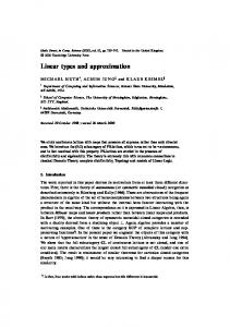
Abstract—Permanent-magnet linear synchronous motors (PMLSMs) with air-cored film coil are applied to servo, miniature, and precision motion-controlled linear machines. On the basis of analytical field solutions, this paper deals with the comparison of the design guidelines, magnetic field, winding electromotive force, required magnet volume, optimal winding thickness, and thrust force for two types of permanent magnet movers. Index Terms—Air-cored film coil, permanent-magnet linear synchronous motor, servo and miniature linear machine. Fig. 1. Three-phase, four-pole, air-cored PMLSM topologies. (a) Vertically magnetized topology. (b) Halbach magnetized topology.
I. INTRODUCTION
P
ERMANENT-MAGNET linear synchronous motors (PMLSMs) have been developed for factory automation, reciprocating servo system, conveyance system, transportation applications, wafer steppers, and so on [1]. In this paper, the air-cored film coil is used for the primary winding of PMLSMs. Air-cored PMLSMs have lower thrust density than cored PMLSMs. However, air-cored stator topology eliminate the detent force and has a low inductance, and thereby improve the dynamic performance and servo characteristic at the expense of a reduction in specific thrust capability [1], [2]. Such a winding is compatible with the servo, miniature, and precision motion controlled linear machines. In this paper, Halbach array is also applied to the mover of air-cored PMLSMs to improve the power efficiency. On the basis of an analytical technique, this paper deals with the design guidelines and analysis of two topologies of PMLSM for the application of the servo and miniature linear machines. One is the PMLSM with Halbach magnetization mover and the other is the PMLSM with vertical magnetization mover. Two types are also compared with magnetic field, winding electromotive force (EMF), required magnet volume, optimal winding thickness, and thrust force.
A. Field Due to Permanent Magnet The governing field equation, in terms of the Coulomb gauge is given by (1) denotes the freewhere is the magnetic vector potential, is the magnetization of permanent space permeability, and magnet. Neglecting end and edge effects and assuming the relative recoil permeability of the permanent magnet to be 1.0, the flux density at the air-gap of the Halbach magnetized topology can be obtained as follows [2]:
(2) is the spatial wavenumber of th harmonic, is the magnet thickness, and is the air-gap length. The magnet array is represented by an infinite Fourier series in horizontal ( -directed) and vertical ( -directed) and , remagnetization components through terms and spectively. For a vertically magnetized topology, are given by
where
II. TWO TYPES OF PM LINEAR SYNCHRONOUS MOTOR Fig. 1 compares four-pole, three-phase, air-cored PMLSMs with: (a) vertically magnetized permanent magnets and (b) a multipole Halbach magnetized magnet, both motors having identical film coil stators. In particular, Halbach magnetized topology has inherent self-shielding property, and thereby does not require a back-iron. Manuscript received February 14, 2002; revised May 22, 2002. The authors are with the Electrical Engineering Department, Chungnam National University, Taejon, Korea (e-mail: [email protected]). Digital Object Identifier 10.1109/TMAG.2002.802130.
(3) is related to the remanence by where the magnetization . Fig. 2 shows the open-circuit magneto-static field and flux density distributions at the lower surface of magnet array of each mover topologies, respectively. For , Fig. 3 shows how the a fixed value of the ratio fundamental component of the air-gap flux density varies with , for each mover topologies. It can be seen that, for is small, Halbach magnetized topology has superior , Fig. 4 shows the flux property. For a fixed ratio of
JANG AND LEE: PM LINEAR SYNCHRONOUS SERVO AND MINIATURE MOTOR
3265
Fig. 3. Variation of peak flux density at the air-gap with magnet thickness.
(a)
Fig. 4. Variation of peak flux density at the air-gap with magnetic air-gap.
(b) Fig. 2. Open-circuit magneto-static field and flux density distributions at the lower surface of magnet arrays.
peak flux density variation with variation of magnetic air-gap.
, which is relative to
Fig. 5. EMF waveforms of Halbach magnetized topology and vertically magnetized topology.
B. Induced Voltage and Electromagnetic Thrust For a three-phase motor, the open-circuit EMF at the stator terminals of a one-phase winding is calculated as [2]
H
(4) is the winding where is the width of the stator winding, is the pole-pairs number, turns per unit cross-sectional area, and and are the mechanical velocity along the and axis, respectively. Fig. 5 compares predicted and measured motor phase EMF waveforms for both vertically magnetized and Halbach magnetized topologies. The air-gap between the magnet array and the stator winding is 1 mm. The velocity along the axis is 0.088 m/s. The EMF of Halbach magnetized topology is sinusoidal, which is compatible with the servo, and precise position
Fig. 6. Variation of =H for Halbach magnetized mover with H =H vertically magnetized mover.
of
controlled linear machines. The electromagnetic thrust acting on the magnet array is given as (5) where is the rms phase current, is the pole pitch, stator excitation frequency, and is the load angle.
is the
C. Magnet Volume Requirements , and For a fixed ratio of variation of the required ratio of
, Fig. 6 shows the for Halbach magne-
3266
IEEE TRANSACTIONS ON MAGNETICS, VOL. 38, NO. 5, SEPTEMBER 2002
Fig. 9.
Photograph of an air-cored PMLSM with Halbach magnetized mover.
Fig. 7. Variation of electromagnetic thrust with the stator winding thickness. TABLE I COMPARISON OF DESIGN AND PREDICTED RESULTS
Fig. 8. Variation of electromagnetic thrust with =H and air-gap.
tized topology, with the ratio of an equivalent vertically magnetized topology. It can be seen that below a certain , the Halbach magnetized topology requires a ratio of lower volume of magnet material. It can also be seen that for the Halbach magnetized topology, the required volume of magnet is increased. material decreases as the ratio of
shows the photograph of air-cored PMLSMs with Halbach magnetized mover. Table I compares the design and predicted results of Halbach magnetized motor and vertically magnetized motor for same required thrust, 12 N. It can be seen that the Halbach magnetized motor has a lower mover volume about 32.8% than vertically magnetized motor. IV. CONCLUSION
D. Optimal Thickness of Stator Windings and , Fig. 7 shows the variaFor a fixed values of tion of the electromagnetic thrust with the stator winding thickness under the constant current density and the constraint of a constant ohmic power dissipation, respectively. Under the constant current density, the electromagnetic thrust of two topologies increases as the winding thickness is increased. Under the constraint of the constant ohmic power dissipation, Fig. 7 indicates that there is an optimal thickness of stator windings for highest electromagnetic thrust in both the vertically magnetized and Halbach magnetized topologies. It was obtained by product of two elements which are the vertical component of the no-load air-gap magnetic flux density and the current of the stator con, Fig. 8 shows the ductors [4], [5]. For a fixed ratio of variation of the electromagnetic thrust with the ratio of and air-gap. III. COMPARISON OF HALBACH MAGNETIZED TOPOLOGY AND VERTICALLY MAGNETIZED TOPOLOGY On the basis of the design considerations stated above we designed the permanent magnet linear synchronous motor with air-cored film coil stator for the application of the servo, miniature, and precision motion controlled linear machines. Fig. 9
Based on analytical field solutions, the magnetic field, required magnet volume, EMF, optimal winding thickness, and thrust of two topologies of PMLSM with air-cored film coil stator have been discussed. It is confirmed that the power efficiency of Halbach magnetized machine is superior to that of vertically magnetized machine. The Halbach magnetized machine with air-cored film coil stator is compatible with the servo, miniature, and precision motion-controlled linear machines to improve power efficiency. REFERENCES [1] J. Wang, G. W. Jewell, and D. Howe, “A general framework for the analysis and design of tubular linear permanent magnet machines,” IEEE Trans. Magn., vol. 35, pp. 1986–2000, May 1999. [2] D. L. Trumper, W. J. Kim, and M. E. Williams, “Design and analysis framework for linear permanent-magnet machines,” IEEE Trans. Ind. Applicat., vol. 32, pp. 371–379, 1996. [3] K. Atallah and D. Howe, “The application of Halbach cylinders to brushless AC servo motors,” IEEE Trans. Magn., vol. 34, pp. 2060–2062, July 1998. [4] S. M. Jang, S. S. Jeong, D. W. Ryu, and S. K. Choi, “Design and analysis of high speed slotless PM machine with Halbach array,” IEEE Trans. Magn., vol. 37, pp. 2827–2830, July 2001. [5] J. Ofori-Tenkorang and J. H. Lang, “A comparative analysis of torque production in Halbach and conventional surface-mounted permanent magnet synchronous motors,” in Proc. IEEE IAS Annu. General Meeting, Orlando, FL, Oct. 1995.