Contents
International Conference on Computer Systems and Technologies - CompSysTech’2003
Complementary Code Keying with PIC Based Microcontrollers For The Wireless Radio Communications Boris Ribov, Grisha Spasov Abstract: The IEEE 802.11b is a Direct Sequence Spread Spectrum (DSSS) system very similar in concept to the CDMA Wireless, using a spread spectrum chip sequence. In the 802.11b the transmission medium is wireless and the operating frequency band is 2.4GHz. 802.11b provides 5.5 and 11 Mbps payload data rates in addition to the 1 and 2 Mbps rates provided by 802.11. To provide the higher rates, 8 chip Complementary Code Keying (CCK) is employed as the modulation scheme. Demodulation of the CCK modulated signal is done coherently by a RAKE receiver implementation which features a channel matched filter and Fast Walsh Transform block. This paper presents implementation of PIC16F84 as a CCK encoder. All low cost PIC based microcontrollers can be used, too. Here we describe the building blocks design of transmitter such as CCK encoder (digital part) and QPSK modulator (analogue part). Key words: CCK, DSSS, Barker’s Code, Spread Spectrum, Wireless LAN, RF, IEEE 802.11
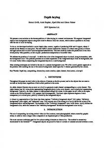
1. INTRODUCTION CCK is a variation on M-ary Orthogonal Keying modulation, which uses I/Q modulation architecture with complex symbol structures. CCK allows for multi-channel operation using the DSSS channel structure scheme [2]. The spreading employs the same chipping rate and spectrum shape as the Barker’s code word [4]. The CCK uses 6 bits to encode the code send, this increase the speed of the 802.11 by 6. The chipping rate is 11 MHz [1], which is the same as the DSSS system as described in 802.11 [2], thus providing the same occupied channel bandwidth. CCK is an M-ary Orthogonal Keying modulation where one of M unique (nearly orthogonal) signal codeword is chosen for transmission [5]. The spread function for CCK is chosen from a set of M nearly orthogonal vectors by the data word. CCK uses one vector from a set of 64 complex (QPSK) vectors for the symbol and thereby modulates 6 bits (1 of 64) on each 8 chips spreading code symbol (Figure 1)[6]. Two more bits are sent by QPSK modulating the whole code symbol. This results in modulating 8 bits onto each symbol.
Figure 1 – CCK modulator The formula that defines the CCK codeword has 4 phase terms. One of them modulates all of the chips (ϕ1) and this is used for the QPSK rotation of the whole code vector. The 3 others modulate every odd chip (ϕ2), every odd pair of chips (ϕ3) and every odd quad of chips (ϕ4) respectively. -
-
International Conference on Computer Systems and Technologies - CompSysTech’2003
e j (ϕ 1+ϕ 2+ϕ 3+ϕ 4 ) , e j (ϕ 1+ϕ 3+ϕ 4 ) , e j (ϕ 1+ϕ 2 +ϕ 4 ) , e j (ϕ 1+ϕ 4 ) , c = j (ϕ 1+ϕ 2+ϕ 3 ) j (ϕ 1+ϕ 3 ) j (ϕ 1+ϕ 2 ) j (ϕ 1) ,e ,e ,e e
(1)
Here, C is the code word with LSB first to MSB last. The data bit stream is partitioned into bytes as (d7, d6, d5…d0), where d0 is the LSB and is first in time. TABLE 1
TABLE 2
PHASE PARAMETERS ENCODING SCHEME
DQPSK MODULATION OF PHASE PARAMETERS
DBIT (d1, d0) (d3, d2) (d5, d4) (d7, d6)
DBIT (di+1,di) 00 01 10 11
PHASE PARAMETER ϕ1 ϕ2 ϕ3 ϕ4
PHASE 0 π π/2 -π/2
The 8 bits are used to encode the phase parameters ϕ1 - ϕ4 according to scheme shown in Table 1. The encoding is based on differential QPSK modulation as specified in Table 2. The multi-path performance of CCK is better than MBOK (M-ary, Bi-Orthogonal Keying) due to the lack of cross rail interference. For CCK, there are 65536 possible code words, and set of 64 that are nearly orthogonal. This is because it really takes 16 bits to define each code vector. CCK suffers less from multi-path distortion in the form of cross coupling (of I and Q channel information) than MBOK. The CCK is directly onto complex chips, which cannot be cross-couple corrupted by multi-path since each channel finger has an Aejθ distortion. A single channel path gain-scales and phase-rotates the signal. A gain scale and phase rotation of a complex chip still maintains I/Q orthogonal. This superior encoding technique avoids the corruption resulting from encoding half the information on the I-channel and the other half on the Q-channel, as in MBOK, which easy cross-couple corrupts with the multipath’s Aejθ phase rotation. 2. RECEIVER CCK codes perform well when used with RAKE receiver in an indoor multipath environment and can be efficiently demodulated. Figure 2 presents typical diagram of RAKE receiver. The classical RAKE receiver has multiple correlators with a delay and a combine circuit following the correlators. For the CCK waveform, this would result in a complex design, as the CCK scheme requites multiple correlators for each of the multiple correlators of the RAKE technique. By linear transformation, the RAKE combiner can be moved to the input of the correlator bank where it is much simpler. In this form, it is called a Channel Matched Filter, because it complements the channel impulse response and therefore corrects for it. This removes the channel effects as far as can be done with a fixed filter, but does not correct for inter-symbol or inter-chip interference (ISI / ICI). The first stage of equalization is ISI cancellation and that involves taking the output of the symbol decisions and then subtracting the left over energy of the previous symbol from the current symbol before demodulation. The next step in equalization is canceling the ICI interference and that makes a more complex process since the ICI depends on which of the 64 vectors was received.
-
-
International Conference on Computer Systems and Technologies - CompSysTech’2003
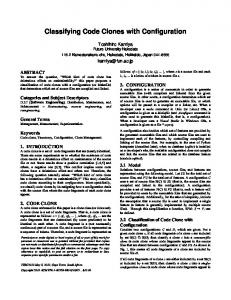
Figure 2 – RAKE receiver with ISI / ICI equalizer 3. CCK RF TRANSMITTER Signal from the CCK modulator (I&Q channels) goes to QPSK modulator. A block diagram for QPSK modulator is shown in Figure 3. Here 1 and 2 are double balanced mixers, 3-phase shifter, 4-local RF oscillator, 5-combiner, 6–band pass filter, 7–power amplifier, 8–antenna. Oscillator 4 generates RF carrier frequency. This signal goes to the phase shifter 3. We used a simple RC-circuit for phase shift at +45° and –45° (illustrated in Figure 4). This can be done for low frequencies. For the higher frequency (UHF bands) can be used micro strip lines with length equal to λ/4. This gave 90° of phase shift for the Quadrature channel (Q-channel). In this case, the In-Phase mixer 1 (I-channel) gets signal directly from the local oscillator 4. After combiner 5, signal reaches power amplifier 7 through the band pass filter 6. Then the signal radiates by the matched antenna 8.
Figure 3 – QPSK modulator
Figure 4 – The phase splitter circuit
The formula that calculates C for the phase splitter (Figure 4) has 2 parameters: splitter resistance - R and carrier frequency - Fo. We used 200ohm resistors for the splitter, due to the input resistance of the mixers 1 and 2. C =
1 2.π .Fo .R
(2)
We used IC-K174PC4 for balanced mixers 1 and 2. K147PC4 is a low cost equivalent of SO42P and is able to work up to 1GHz. SO42P has maximum working frequency of 200MHz. -
-
International Conference on Computer Systems and Technologies - CompSysTech’2003
4. IMPLEMENTATION OF THE CCK ENCODER This part presents the construction of a PIC16F84-based module as a CCK encoder for wireless communication devices. The PIC16F84 is a low cost, high performance CMOS 8-bit FLASH RISC microcontroller with integrated 68 bytes of RAM, 64 bytes of EEPROM, 1K Flash Program Memory, 13 I/O pins and other features [3] that make it suitable for the encoder module. Basic function of this module is to generate product code on pins 1 and 2 on J1, according to the CCK specification. Data comes from pin 4 on J1. U1 generates clock signal CLK to J1 (pin 5) when PTT signal is in high condition (transmission). Controller generates PTT when there is data for transmission. Figure 5 – Circuit diagram of the CCK modulator
Figure 6 – Block diagram of the program U1 generates CLK signal to get current bit from data stream (at pin 4 on J1). Then U1 calculates product stream for In-Phase (I) and Quadrature (Q) channels. These product streams are sent to pins 2 and 1 on J1 respectively. -
-
International Conference on Computer Systems and Technologies - CompSysTech’2003
Figure 6 shows block diagram of the microcontroller’s program. Initialize routine sets I/O ports’ direction, oscillator type and some timing parameters for the microcontroller. Then program checks for active PTT signal at pin 8. If it is in inactive state, program loops. If this pin is active, CLK is generated by set bit 0 of PORT B (pin 6). After a while data bit is read from pin 7 (bit 1 of PORT B). Data bits are read until a symbol of 8 bits is formed in the MUX. Then first six bits from the MUX set pointer to an array with pre-defined bytes. Each pre-defined byte contains 8bit code. This code is the CCK code vector. The next step is to combine the selected code vector with the last two bits from the MUX. This combination presents in Bitwise XOR with each of them, generating new two independent temporary bytes. The result is two 8-bit codes, one for In-Phase channel and one for Quadrature channel. In the last step these codes are sent out. After that program loops in waiting for a new transmission. 5. CONCLUSIONS This paper describes a new method to improve the performance of block codes for general multipath environments in radio transmission. We showed that CCK codes have robust performance in a variety of multipath environments. DSSS with use of Barker’s code [4] is more stable according to the long range and distance between transmitter and receiver in comparison with CCK. The multi-path performance of CCK is better than MBOK. The CCK waveform has better Eb/N0 performance than DPSK. Transmitter’s part of the CCK transceiver is a low cost effective, but the receiver’s part is more complex. 6. REFERENCES [1] HFA3861A Data Sheet, Intersil Corporation, Answer FAX Doc. No. 4776 [2] IEEE Std 802.11 - 1999. Wireless LAN Medium Access Control (MAC) and Physical Layer (PHY) Specifications. IEEE Standards Dept., 1999, www.ieee.org/~standards/ [3] Microchip PIC16F8X Data Sheet, Microchip Technology Inc., 1998 [4] Spasov, G.V. and Ribov, B.Y., “Spread Spectrum for Wireless Systems using PIC based micro-controllers as a Spreader", Proceedings of the Eleventh International Scientific and Applied Science Conference, "ELECTRONICS ET'2002", Sozopol, September 25-27, Bulgaria, book 2, ISBN 954-438-327-1, pp.89-94, 2002 On-line version at: http://www.qsl.net/lz1bjr/dsss.pdf [5] T. D. Chiueh and S. M. Li, "Trellis-Coded Complementary Code Keying for High-Rate Wireless LAN Systems", IEEE Communications Letters, Vol. 5, No. 5, pp. 191-193, May 2001 [6] Bob Pearson, “Complementary code keying made simple”, Application note 9850, May 2000, http://www.intersil.com/data/an/an9/an9850/an9850.pdf 7. ABOUT THE AUTHORS Assist.Prof. Grisha Valentinov Spasov, Technical University – branch Plovdiv, E-mail:
[email protected],
[email protected] eng. Boris Yosifov Ribov, M.Sc, LZ1BJR, phone: +359 (887) 261-866, E-mail:
[email protected],
[email protected] Contents
-