COMPLEX SYSTEM SOLUTION FOR MIROSOT SOCCER’S ROBOT Jiri Kotzian 1, Jan.Kozany 1, Zdenek Machacek 1, Vilem Srovnal Jr 1, Petr Tucnik 2 1
Department of Measurement and Control, Department of Computer Science VSB-Technical University of Ostrava, 17. listopadu 15, 708 33 Ostrava-Poruba CZECH REPUBLIC {jiri.kotzian.,zdenek.machacek,vilem.srovnal1,jan.kozany}@vsb.cz 2
Department of Information Technologies University of Hradec Kralove Rokitanskeho 62, 500 03 Hradec Kralove CZECH REPUBLIC
[email protected]
Abstract The paper presents design and implementation of embedded control system, communication system, and strategies control algorithms for the robot soccer team. Our research work is focused on advanced hardware and software concept of robot units for the robot soccer and low level strategy algorithms. Developed robots contain powerful and safe hardware components, communication module and software structured algorithms. These components enable various functions, safety control and a complex diagnostic of robot states.
1 Introduction The robot soccer is a discipline for two teams of robots. The robot soccer combines work and amusement. The game puts a lot of requirements on hardware, firmware and software of the robot and also on cooperation between developers. Our research is focused on development of safer, faster and more reliable product; compared to older robot soccer units. A development of our research team section is concentrated on robot units’ hardware and software creation, a robot’s communication and regulators design and implementation. Our research colleges solve other important developing function parts, which are necessary for a whole complex effectual solution of the soccer
robots application. A robot control is realized by very powerful and fast DSP digital signal processor. This processor enables very sophisticated computations in a short execution time. Moreover, a processor capacity is large enough for the other system improvements. The new advanced software implemented into robots uses advantages and extended possibilities of this DSP digital signal processor and other hardware components. The communication is solved by a special communication principle. The newly designed hardware solution is divided into two PCB boards, where one board is used for controlling and the other one as a source for powering electronics. A software algorithm is divided to functional subroutines. A design of regulators for accurate and efficient robots function is important part of research. A mathematical program environment Matlab 7.0 is used for the regulator design and data regulator visualization. The low level strategies (called low strategies in further text) are designed to perform dynamical changes of robot‘s parameters. The low strategy is able to control robot‘s behaviour and movement. High level strategy of the control mechanism of the robot soccer team is generally difficult to design. Because every individual player has to make decisions accordingly to his actual situation and the team as a whole has to coordinate its actions, there is a need to make proper decisions and to make them quickly. For every decision-making cycle, there is a time limit given primarily by the speed of image processing mechanism.
2
Robot connection and communication
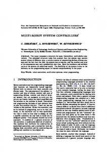
The control system of robot for robot soccer has to fulfill two main requirements: First requirement is to control two direct current motors. Second requirement is fast and safe communication with the base station. The core of the control system is the controller. The microcontroller has to have two quadrature timers, SPI interface and three control pins for communication, three AD converters for current sensing and battery monitoring, four PWM modulators and several control pins for motor driver control. Also the possibility of external memory and flash connection is needed for the future (the next generation will be able to work as a cooperating group with local intelligence on each robot). For following a lot of necessary connections, peripheries and speed the Freescale 56F805 hybrid controller was selected. This controller also supports JTAG interface for programming and debugging. Controlled motor is 6V DC and 1.2A peak. For controlling the motor, the driver with high efficiency and low output saturation voltage is needed. There is only a little space for chilling. The Freescale MC33887 was selected due to MOS transistor output (no saturation voltage). The problem is that the controller is 3.3V architecture and motor driver is 5V. Inputs of the controller are 5V tolerant but input of driver is 5V CMOS, so 3.3V from controller is not enough. It is necessary to equip each controller output pin with diode and resistor. Cathode is connected to the controller output. Anode is connected to the driver input and to 5V through 10k resistor. This connection shifts output voltage upon 0.7V.
of wattage looses). For other power saving it is possible to switch off power for optical sensor and motors. There are three DC/DC converters in the control system: one continuous for microcontroller and communication 3.3V/1A; one switchable for motors 6V/3A and one switchable for optical sensors and drivers 5V/1A. The motor is controlled using from 10 to 30 kHz PWM signal, so we need a DC/DC converter on high operating frequency. We also need to set output voltage for the given periphery. For these reasons and because of availability, the LM259x series was used.
Power source Battery pack 10.8V
Anten Transceiver Nordic
nRF2401
Controller
Consumption
3.3
150-200
Communication
3.3
20-200
Driver
5
20
Optical sensor
5
30-130
Motor
6
0-2400
Table 1: The power consumption
The robot is powered by the Battery (9 cells). Output voltage of the battery is changing from 9V to 13V. Some parts have large power consumption. For these reasons, a DC/DC converter is needed (linear supply will have lot
R position sensor ADNS2620
JTAG DSP Freescale 56F805
Board 2
DC/DC voltage [V]
L position sensor ADNS2620
Board 1
3.3V/1A
Part Supply [mA]
Board 3
L motor Driver MC33887
R motor Driver MC33887
L motor Faulhaber 006SR
R motor Faulhaber 006SR
5A/1A DC/DC 6V/3A DC/DC
Figure 1: Blocks diagram of the Robot control system
To satisfy the second requirement we need a band with low degree of disturbances. Usually, there is a 433MHz band used, but there is a lot of users and transitions. Used frequency has been moved to 2.4 - 2.5 GHz ISM band. The nRF2401 has been selected, which is a single-chip radio transceiver for given band. Used channel is selectable by the software. For time base of the nRF chip precision and stable oscillator is needed.
3
Embedded control system
An embedded system is the robot’s control system for fundamental calculations, algorithms execution and communication. This system performs pre-defined tasks and it has specific requirements. Programs have to run with real-time and application-specific integrated circuit limits. While developing a project, the embedded system contains a DSP digital signal processor for process and signal computation. This new improvement of the diagnostic system design is very powerful and it could control devices better and faster than the old ones. Thanks to this embedded system, we can automatically monitor values, execute, analyze, monitor the equipment state, and react to system operation. For robot soccer applications, it is necessary to process complex computations in a very short time (RT - real time). Therefore, for the processing, the digital signal processor DSP is most suitable. DSP is a Harvard architecture processor with special features. The architecture enables using more system buses for the data and instruction transfer inside the processor. DSP is a RISC (Reduce Instruction Set Computer) processor type. One of DSP special features is Pipe-lining. It means that they process more instructions in one instruction cycle. It enables using the special MAC instructions for filtering. The digital signal processor FREESCALE DSP 56F805 is used in this project. Maximum core frequency is 80MHz, and 8MHz crystal. The program memory is internal FSRAM 64K x 16 bits and 64K x 16 bits is a data memory. It is a 16 bit processor with a sufficient performance and number of peripheries. For programming, there is the development software - Code Warrior – allows transparent and comfort programming in C and Assembler languages.
4
write in C or Assembler programming languages. The programming environment CodeWarrior enables comfortable and complex programming. This programming environment allows monitoring and setting of values, registers, breakpoints, memory, debugging, and the processor activity. The environment contains function libraries, which can be helpful for programmer. The developing program algorithm in DSP allows complex operations and sophisticated computation without complicated electronic circuits. Moreover, it is possible to change parameters, functions or parts of program algorithm just by programming, without changing of the electronic circuit. The programming environment contains Embedded SDK library too. This library allows use of special DSP functions, which are common and useful for digital signal processing computation and evaluation. For example, computations included in this library are Fast Fourier transform FFT, FIR and IIR filtering, correlation and others. This manner of programming by libraries functions makes the special functions programming easy. But for control of peripheries, interrupts and basic control processors functions it is better to use programming directly registers. The developing application should be very powerful, accurate and operation execution should be performed in a very short time (real time). Almost all requirements for this developing application are observed and guaranteed by chosen hardware and the created programming algorithm.
Software development environment
An implemented developing program algorithm for the robot unit is saved and running inside DSP digital signal processor. The program is implemented with the help of programming environment Metrowerks CodeWarrior 5.5.1, which is intended for processors DSP Motorola. Used processor is fast enough for all needed operations in this sophisticated project. Metrowerks CodeWarrior programming environment runs on PC personal computer and this PC is connected by parallel RS485 port. Processor state and program values could be watched by serial RS232 connection of DSP and PC. The developing program algorithm is written in C programming language. It is possible to
Figure 2: Programming environment FREESCALE Metrowerks CodeWarrior
5
Movement regulation
6
The constants of the PI controller are proposed on account of identification of the robot system. Identification of the system is made as the response on the step unit. The chosen model for identification is called Broïda model. Broïda studied the position of the inflection point for the systems from order 2 to order 6. (Broïda,V., 1969).
G (s ) =
G0 e − sL (1 + Ts )n
(1)
He proposed in the first approximation to compute the model parameters of the equation by determination abscises the time t1 and t2 for witch the system response reach 28 % and 40 % respectively of the final value: y1 (t ) = 0.28G0
y2 (t ) = 0.40G0
(2, 3)
Strategy algorithms
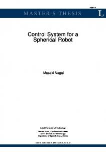
Low strategies are very important for robot’s functionality. Values of actual robots position, movement and state are useful for low strategies and to adapt control decision. In fact, there are no serious decisions made at this level. The strategy module consists of three levels of decision-making. The high level is responsible for situation recognition and team coordination, selection of a proper reaction to the given situation is also made here. On the second level – the middle level strategy – are made decisions regarding every individual agent-robot. The proper realization of selected action is this level’s responsibility. At the low level, there are made all the necessary adjustments and corrections needed while starting or finishing movement, turning, moving with the ball, non-collisional movement and similar activities. This is the most important part of work at this level of strategic control mechanism.
This supposes the knowledge of the system static gain. With this value we compute T = 5 .5(t2 − t1 )
(4)
L = 2.8t1 − 1.8t2
(5)
The each robot has a bit different mechanical gearing. But it is not important to identify each robot separately. The important affair for PI controller’s constants tuning is frictional force and the concrete drive slip. We have to test settings of the robot on the specific surfaces. Total identification of the robot before the movement is conditional mentioned difficulties.
Figure 4: Low strategy testing window
Figure 3: Robot unit for the robot soccer
The rest of activity remaining at the low level of strategy module is to perform correct transformation of the decisions made at the upper levels into simple hardware instructions. These are signals, which is the robot able to understand. Then are these simple instructions send by transceiver to the robot and processed by it. The instructions are very simple, used only to set the speed of the left and right wheel of the robot. This is, in fact, the only output of the strategy
module – all complex decisions are translated into atomic activities and elementary orders. Simplification of the communication to this level is useful, because it allows faster transfer of data between the control mechanism and the robot.
Acknowledgements The grant Academy of Sciences of Czech Republic supplied “Strategic system control with multi-agents“, number: 1ET101940418, for a years 2004 -2008.
References [1] Freescale Semiconductor, Inc. 56F805 16-bit Hybrid Controller Rev. 12.0, 02/2004 [2] Freescale Semiconductor, Inc. 33887 -5.0A H-bridge with load current feedback, rev 9.0, 10/2004 [3] Nordic Semiconductor. nRF2401 - single-chip radio transceiver, rev 1.0, 03/2003 [4] O’Dwyer A., (2003). Handbook of PI and PID Controller Tuning Rules, Imperial College Press, Singapore 2003, ISBN 1-86094-342-X [5] Broïda,V., (1969) Extrapolation des résponses indicielles apériodiques. Automatisme, vol. XVI, 1969 [6] Kester Walt (2000). Mixed signal and DSP design techniques. Analog Devices, Inc. ISBN 0-916550-230.
Figure 5: Comparison of the real pitch and the computed view by the camera display system
7 Conclusion
[7] Smith W. (1997). The Scientist and Engineer's Guide to Digital Signal Processing. California Technical Publishing.USA.ISBN0-9660176-3-3 [8] Stranneby: Digital Signal Processing DSP & Applications (2000). Newnes. Great Britain. ISBN 07506-48112. [9]
The solution of the robot control system brings enhancement in the area of disturbance reduction and expandability. Multi-board conception brings possibility of fast interchange necessary parts. The firmware allows behavior of the robot to be more precise and harmonious. This system design and realization is a very interesting and formidable task. It is necessary to use a complex mathematical theory and to support it with digital signal processing and computer science. Specific problems with play recognition and game figures, physical methods, digital signal processing, complex expert computer system are solved by the complex solution for MiroSot soccer robots and they are usable for practical tasks in industry too.
Kozany,J., Tucnik,P., Srovnal,V.: Multicriterial Decision-Making in Multiagent Systems. In Lecture Notes in Computer Science. Ed. Vassil N. Alexandrov, Geert Dick van Albada, Peter M.A. Sloot, Jack Dongarra, Berlin: Springer , 2006, 2006/3993, p. 711 - 718, ISBN: 3-540-34383-0, ISSN: 0302-9743
[10]Kozany,J., Tucnik,P., Pokorny,J., Lukas,D., Srovnal: Software structure of a control system for the mirosot soccer game. Ed. Norman Weiss, Norbert Jesse, Bernd Reusch, Dortmund: University of Dortmund, 2006, p. 183-188, ISBN: 3-00-019061-9