Component-Average based Distributed Seismic Tomography in Sensor Networks Goutham Kamath
Lei Shi
Wen-Zhan Song
Department of Computer Science Georgia State University {gkamath1,lshi1}@student.gsu.edu,
[email protected] Abstract—Existing volcano instrumentation and monitoring system use centralized approach for data collection and image reconstruction and they lack the capability of obtaining real time information. A new distributed method is required which can obtain a high resolution seismic tomography in real time. In this paper, we present a component-average distributed multiresolution evolving tomography algorithm for processing data and inverting volcano tomography in the network, while avoiding centralized computation and costly data collection. The new algorithm distributes the computational burden to sensor nodes and performs real time tomographic inversion under constraints of network resources. We implemented and evaluated the algorithm in a customized simulator using synthetic data. The experiment results validate that our proposed algorithm not only balances the computation load but also achieves high data loss tolerance.1 Keywords—Distributed Computing, Seismic Tomography, Sensor Network
I.
I NTRODUCTION
Existing volcano instrumentation and monitoring system lack the capability of obtaining real time information and also recover the physical dynamics with sufficient resolution. The current technology available involves collecting the raw seismic data from sensors to a centralized database for post processing and analysis. This model introduces a bottleneck in computation and increases the risk of data loss in case of node failures especially the base station. Seismic sampling rates for volcano monitoring are typically in the range of 16 − 24 bit at 50 − 200Hz. These high fidelity sampling from each node make it extremely hard to collect raw, real-time data from a large-scale (e.g., hundreds to thousands), dense sensor network, due to severe limitation on energy and bandwidth at current, battery powered nodes. Due to these challenges, many of the most threatening active volcanoes worldwide use fewer than 20 nodes [22]. This practical restriction limits our ability to understand volcano dynamics and physical processes inside volcano conduit system. Substantial scientific discoveries on the geology and physics of active volcanism would be imminent if seismic tomography resolution could be increased by an order of magnitude or more (e.g., hundreds even thousands). Using the current sensor network technology it is possible to deploy and maintain a large-scale network for volcano monitoring and utilize the computing power of each node for distributed tomography inversion. Tomography algorithms commonly in use today cannot be easily implemented under 1 Our research is partially supported by NSF-CNS-1066391, NSF-CNS0914371, NSF-CPS-1135814 and NSF-CDI-1125165.
field circumstances proposed here as they rely on centralized algorithms and require massive amounts of raw seismic data collected over central processing unit. Thus, real-time volcano tomography requires a practical approach which is scalable and efficient with respect to tomography computation algorithm. In this paper, a component-average distributed multiresolution evolving tomography algorithm is proposed to distribute the tomographic inversion computation load to the network. The sensor nodes deployed use the arrival times of seismic events and event locations to derive a 3D tomographic model of the velocity structure within the volcano. As more earthquakes are recorded the velocity model evolves over time to refine the existing one. This approach, apart from decentralization is in sharp contrast to the traditional centralized processing. This paper mainly focuses on distributed tomography algorithm, while assuming that the arrival time of event at each node has been extracted from the raw seismic data by each node itself [21], [24]. To our best knowledge of literature, our work is the first attempt to compute seismic tomography in sensor networks. The algorithm proposed here has application to fields far beyond the specifics of volcano, e.g., oil field explorations have similar problems and needs. The rest of the paper is organized as follows. Section II presents the background knowledge of seismic tomography. In section III, we discuss the related works of distributed algorithms in wireless sensor networks. The algorithm and design of distributed tomography inversion are presented in section IV. Simulation results are discussed in section V. We then conclude the paper in section VI. II.
BACKGROUND S TUDY
Seismic Tomography: The principle behind seismic tomography is adapted from the medical imaging domain where the travel times of the elastic waves are used to probe the internal structure of the media. However there is significant difference between these two methodology, mainly pertaining to size of the structure and event generation scheme. The relationship between the travel time and the velocity model is non-linear and the ray path of the acoustic wave traveling in volcano may be highly curved mainly due to the sheer size and complexity of the volcano structure. Typically the ray source in volcano tomography is an earthquake event where the distribution of the ray path is highly non-uniform unlike the uniform short distance rays generated in medical imaging. These differences indicate that special care must be taken when techniques borrowed from the medical field are applied to seismic data.
2
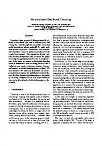
The basic principle behind 3D seismic tomography is to use the arrival time of the P-wave to derive the internal velocity structure of volcano. This approach is called traveltime seismic tomography and the model here continuously evolving and refined, as more earthquakes are recorded. Below we explain the three basic principles involved in travel-time seismic tomography. i) Event Location: Once an earthquake occurs, seismic disturbances are detected by the nodes which can further estimate the arrival time. Using this estimated arrival times, Geiger [5] introduces a technique to estimate the earthquake location and origin time. This is a classic and widely used event localization scheme which uses iterative method and GaussNewton optimization to determine the time and location of the event. ii) Ray Tracing: This is the technique of finding the ray paths from the seismic source locations to the sensor nodes with minimum travel time, following an event. Once earthquake occurs, the seismic rays originated from these event perturbs and register the anomalous residuals. Given the source location of the seismic events and current velocity mode of the volcano, ray tracing is to find the ray paths from the event source locations to the nodes as shown in Fig. 1(b). iii) Tomographic Inversion: The ray paths traced in turn is used to estimate the velocity model of the volcano. Inheriting the concept from medical tomography, volcano can be partitioned into smaller blocks as shown in Fig. 1(c). This allows us to formulate the tomography problem as a system of linear equation consisting of a large, sparse matrix. Suppose there are N sensor nodes and E earthquakes and x∗ be the reference slowness (reciprocal of velocity) model of the volcano with resolution M blocks. x∗ is the sum of x0 , unperturbed model and x a small perturbation i.e. x∗ = x0 + x. Let b∗i = [b∗i1 , b∗i2 , · · · , b∗iE ]T , where b∗ie be the travel time experienced by node i in the eth event. Based on the ray paths traced in step (2), the travel time of a ray is the sum of the slowness in each block times the length of the ray within that block, i.e., b∗ie = Ai [e, m] · x∗ [m] where Ai [e, m] is the length of the ray from the eth event to node i in the mth block and x∗ is the slowness of the mth block. Let b0i = [b0i1 , b0i2 , · · · , b0iE ]T be the unperturbed travel times where b0i = Ai [e, m] · x0 [m]. In the matrix notation we have following equation, Ai x ∗ − Ai x 0 = Ai x
(1)
where Ai ∈ RE×M . Let bi = [bi1 , bi2 , · · · , biE ]T be the travel time residual such that bi = b∗i − b0i , equation (1) can be rewritten as, Ai x = bi (2) Since each ray path intersects the model at a small number of blocks, the design matrix , Ai , is sparse. For the system with N sensor nodes, the equation of the entire system would be, Ax = B
(3)
where B = [b1 , b2 , ....bN ]T , bi = [bi1 , bi2 , ....., biE ]T and A = [A1 , A2 , ....AN ]T .
III.
R ELATED W ORKS
Seismic Tomography: Static tomographic inversion of 3D structure have been widely studied since late 1970’s [9] which are applied to oil field exploration and volcanoes. Only in recent yeears, passive seismic data obtained from the few tens of nodes have been studied to invert the volcano tomography. These centralized technique have been implemented and studied for volcanoes such as Mount St. Helens [12], Mount Rainier [16]. However, the resolution of such inversions is typically in kms or even tens of kms. Higher resolution image is hard to obtain from the existing sensors as they are few in numbers which cannot cover the entire region of interest. Another option is to scale the existing system by adding more number of nodes in strategic points. Even if this seems to be logical solution, scaling these centralized system is very tedious task and sometimes impossible due to the data load. These centralized schemes involve multiple active-source recordings spanning data over multiple years [13]. These voluminous data accumulated over years cause bottleneck in communication over wireless network and also introduce huge delay due to processing time. To achieve effective disaster warnings and timely response, new schemes and methodologies are required to solve the real-time volcano imaging problem. This is the main motivation for developing a new real-time volcano tomographic inversion algorithm. Distributed Linear Least Square: Methods for solving system of linear equation (3) can be mainly classified into direct methods and iterative methods. Although progress has been made in reducing the complexity of direct methods for solving sparse problems [1], [23], [11], many large sparse problems particularly in image reconstruction are still hard to solve. Iterative methods are widely used when the elements of matrix in equation (3) is large, sparse and unstructured [19]. In literature there are few studies on consensus-based distributed least-square algorithms [15], [20] designed for parallel systems. These algorithm adopts weighted sum of local estimates to achieve consensus. Each sensor node maintains its own local estimation and exchanges information locally to achieve consensus. These methods are primarily designed for estimation of low dimensional vector and typically in parallel environment. To achieve global convergence, consensus protocols generally requires a longer execution time and frequent communication between neighbor. In seismic tomography network this approach not only means high communication overhead but also longer delays involving many multi-hop communications. Therefore, the consensus-based distributed least square algorithms are not suitable for high-resolution seismic tomography in sensor networks. Another method originally proposed for parallel computing is the multi-splitting solution of the least squares problem [18]. This method partitions the system into columns instead of rows letting each processor to compute a partial solution. Later these partial solutions are exchanged to reach the global convergence. Column splitting of equation (3) in seismic ~ Since we have tomography means splitting of travel time B. the information of the total travel time from event source to ~ exactly and any heuristic will add node, we cannot divide B error in addition to existing system noise. Apart from that, this method is only linearly convergent and the communication cost
3
Ray Tracing
Event Location
Tomographic Inversion
Legends Sensor Node Seismic Wave Magma
Estimated Event Location
Magma
Estimated Magma Area Blocks on Ray Path Earthquake
Fig. 1.
Earthquake
Procedures of Seismic Tomography Inversion
~ which in our case is very expensive as it requires exchanging B increases with occurrence of earthquake. Due to this reason column partitioning is not suitable for seismic tomography. The most popular iterative method was proposed by Kaczmarz (KACZ) [10] which is a form of alternating projection method. This method is also known under the name Algebraic Reconstruction Technique (ART) in computer tomography [8]. This algorithm do not require the full design of matrix to be in memory at one time and can incorporate new information (ray paths), on the fly. The vectors of unknowns are updated after processing each equation of the system and this cycle repeats till it converges. The other variants of iterative methods are symmetric ART (symART) [3] and Simultaneous ART (SART) [2]. In SymART, one cycle in ART is followed by another cycle in reverse order while in SART, block of equations are projected instead of just single equation. All these methods are centralized and cannot be directly applied to distributed seismic tomography. The block parallel versions of ART have also been proposed and widely used algorithms among them are component averaging (CAV) [5], Block Iterative- Component Averaging (BI-CAV) [4] and component-averaged row projections (CARP) [7]. These block-parallel algorithms use string averaging technique to combine the intermediate result of each block by taking regular weighted average. The main idea here is to utilize the sparsity of the system matrix as the weight for averaging. A survey paper comparing various block parallel methods based on their performance on GPU’s are discussed in [6]. From the above methods, CARP is more generalized and places no restriction on the system matrix or the selection of blocks. CARP does not require any pre-processing or preordering of the matrix and provides very robust method unlike any other block parallel algorithm for solving large sparse linear system. In CARP, a finite number of KACZ method is applied in each block and the resulting point in each block is averaged to get next iterate. It is also proved to converge for large scale systems [7]. In this paper we propose Component Average Distributed Multi-resolution Evolving Tomography (CA-DMET) variant of block-parallel algorithm modified to fit into seismic tomography. A multi-resolution evolving tomography which refines the velocity model with occurrence of event is combined with the above mentioned component average technique to generate seismic image in real time. To our best knowledge of literature, our work is the first attempt to compute seismic tomography in sensor networks.
IV.
A LGORITHM
In this section we develop a new seismic tomography algorithm with a multi-resolution evolving scheme to distribute the computation load and compute the least-square solution of the seismic tomography inversion problem in the network. In this algorithm seismic sensor which are deployed on top of the volcano, are grouped into clusters and each cluster has cluster head. Each seismic sensors in that cluster sends its ray information to its cluster head. The cluster heads then compute the partial slowness perturbation (xlocal ) and combine with partial slowness perturbation obtained from other cluster heads using component average to obtain next iterate (xk ). This process is repeated until we reach a threshold and finally we obtain the global slowness perturbation (x) which is then added to initial model (x0 ) to obtain systems slowness. In this section we first present the problem formulation and later discuss the algorithm in details. Suppose there are N sensor nodes in the network and E ray paths are traced on each sensor nodes, following some earthquake events. From section II the seismic tomography model will be of the form Ax = B
(4)
where B = [b1 , b2 , ....bN ]T , bi = [bi1 , bi2 , ....., biE ]T and A = [A1 , A2 , ....AN ]T . Typically the seismic tomography model shown in equation (4) is quasi-overdetermined, inconsistent and contains measurement noise. Therefore, we need to add some form of regularization to avoid strong, undesired influence of small singular values dominating the solutions. This can be achieved by applying regularization parameter for determining the leastsquare solution xLS , i.e., xLS = arg max kB − Axk2 + λ2 kxk2 x
(5)
where λ is the trade-off parameter that regulates the relative importance we assign to models that predict the data versus models that have a characteristic, a priori variance. A variant of ART called Bayesian ART(BART) can be used for solving equation (4) by minimizing equation (5). Suppose the system Ax = b is inconsistent, then we have Ax + r = b where r is chosen from any given x. Then the system is transformed to a well-posed problem. Now x and r can be
4
solved simultaneously using following iterative equation, d(k)
=
x(k+1) r(k+1)
= =
(k) (ri
+ λaTi · x(k) ) 1 + λ2 kai k2 x(k) + λd(k) ai r(k) + d(k) ei ρ(k)
λbi −
where ei is a unit vector with the ith component equal to one, λ is the regularization parameter. Note that in Bayesian ART method, we need an additional vector r of length E, but in k th step only one component of r(k) needs to update. This method has been proved to be a leastsquares method and used for seismic imaging in [14]. The key challenge here is to solve the regularized least-square equation (5) in a distributed manner under the constraints of network resources and our proposed algorithm borrows the idea from component average to achieve this. A. Component-Average Distributed Multi-Resolution Evolving Tomography
In this section, we discuss the details about multi-resolution evolving scheme and give the description of the proposed algorithm. As discussed in the section II, the computation of time travel residual dependents highly on the slowness reference model. Initially with no system information we generate the unperturbed model x0 based on previous seismic data. Although this model could have been altered (shifting of magma beneath), it provides a good initial guess for the computation. However from the experiments researchers have found that the tomography inversion is highly sensitive to reference model. Keeping this in mind, we introduced multiresolution evolving tomography scheme which computes a coarse resolution tomography when a small amount of earthquake events occur using the initial model x0 . This model is then refined based on courser tomography and used to compute finer resolution with the occurance of more earthquakes. This idea is based on theoretical framework of multigrid methods [17], [25] which accelerates the global convergence of a basic iterative method, adjusting parameters dynamically by solving coarser problem. With the multi-resolution evolving scheme, the intermediate results can be retrieved in real time without having to wait till all the computation is done.
Algorithm 1 Component-Average Distributed Multi-resolution Evolving Tomography Initialize 1: Node ID id, 2: Initialize the resolution level l ← 1 3: Initialize the final resolution level L 4: Initialize the starting resolution dimension d 5: Current resolution dimension Q = 2(l−1) d × 2(l−1) d × 2(l−1) d 6: P partition Cluster {C1 , C2 , ..., CP } 7: Send initial slowness model xl of resolution Q to each cluster Repeat 1: Upon the detection of an event 2: Trace the ray path ae for every node 3: Send ~ae and be from each node to nearest cluster Ct , 4: for 1 ≤ t ≤ P 5: Upon the reception of ~ ae and be to the nearest cluster C 6: For each 1 ≤ j ≤ Q, calculate sj 7: Where sj = |Ij | = {1 ≤ t ≤ P |xj has nonzero 8: coefficient in some equation of cluster Ct } 9: k ← 0, xk ← 0 10: while not converged do 11: In Every cluster Ct , for 1 ≤ t ≤ P do in parallel 12: Perform some finite number of Bayesian ART 13: (BART) on system of equations with initial guess 14: xk 15: Aggregate the partial slowness perturbation x ¯t 16: from all cluster and find the next iterate: ( x ¯tj if sj = 1 (k+1) PP 17: xj = t 1 x ¯ if sj > 1 j t=1 sj (k+1) xj
18: Send to all the cluster Ct 19: k ←k+1 20: end while 21: x ← xk−1 22: Upon the completing BART and obtaining final x 23: Update slowness model: xl = xl + x 24: l ←l+1 25: if l is equal to L 26: TERMINATE 27: else 28: Q = 2(l−1) d × 2(l−1) d × 2(l−1) d 29: Increase the resolution of xl to Q 30: endif
Sensor Nodes [x’]
Cluster Head
[x’]
[x’]
Tree based aggregate
[x’]
[x’]
[x’] Partial Slowness
[x’]
[x’]
[x’]
[x’]
Fig. 2.
Clusters and Cluster Heads
Now we give the formal description of ComponentAverage Distributed Multi-Resolution Evolving Tomography (CA-DMET) algorithm, see Algorithm 1. Suppose there are N sensors deployed on the volcano, we partition them into P clusters i.e. C1 , C2 , . . . , CP as shown in Fig. 2. Let Q = 2l−1 d × 2l−1 d × 2l−1 d be the current tomography resolution where l is the level of different resolution and d is the initial resolution dimension. The system Ax = b can be partitioned by row as, [A1 , A2 , . . . , AP ] · [x1 , x2 , . . . , xQ ]T = [b1 , b2 , . . . , bP ] where rows in Ai represents the ray information in cluster Ci , bi represents the travel time residual of rays in the cluster Ci and xj denotes the slowness perturbation of the j th grid in a 3D tomographic cube of dimension Q. Initialize line 1-7: Each node initialize its ID, starting resolution d and final resolution L. Each node is assigned to its cluster head {C1 , C2 , ..., CP }. This tells each node where to send its ray information. Current resolution dimension Q is set to d × d × d and resolution level l is set to 1. A slowness model x(l) of resolution Q and for level l = 1 is used as an initial guess for ray tracing.
5
Repeat line 1-3: After the initialization, each node will perform specific action based on the event detection and message reception. Once an event is detected by some node, the node will perform the ray tracing algorithm (assuming each node is aware of event location) and get the ray path. Then each node will compute and send the complete ray information to the nearest cluster head. Repeat line 4-17: Once all nodes send the ray information to the cluster heads, a parameter sj for all 1 ≤ j ≤ Q is calculated by the cluster heads. sj is the number of clusters which has nonzero coefficient of particular xj . Once sj is calculated, each cluster head simultaneously performs some finite number of Bayesian ART (BART). The next iterate is determined by component averaging technique given by PP (k+1) xj = s1j t=1 x ¯tj . Here a tree based aggregation protocol (k+1)
is used calculate sum and broadcast back xj to all the (k+1) cluster head. The updated xj is used as an initial guess for the next iteration. A stopping criteria is used to stop BART and the final slowness perturbation is sent to all the sensor nodes. Repeat line 17-26: Once a sensor node, receives the slowness perturbation x from Cp . It will update the slowness model xl = xl + x. After all the slowness perturbations from the cluster heads in the network has been received, i.e., the entire slowness model has been updated and the resolution level l is set to l + 1. The algorithm will TERMINATE if the required resolution is met, otherwise the node calculates the current Q and increase the resolution of slowness model xl to Q. There are different ways to increase the resolution of the model, e.g., all the blocks in higher resolution just use the slowness value of the block it belongs to in the lower resolution. Notice that the algorithm here is based on a cube tomography model, in reality the model is not always a cube and the cluster may depend on the deployment of the sensor network. This algorithm can be applied to different models, the only thing needs to be changed is the resolution evolving and clustering scheme, i.e., how to set Q and P . V.
E VALUATION AND VALIDATION
In this section, we outline the general setting of the experiment and present the results. Since volcano tomography is similar to computerized tomography we use similar convergence measure and test cases for validation. Our evaluation uses synthetic magma and earthquake events designed in a customized simulator. First, a data generator is implemented to generate a magma area and earthquake events assuming the tomography model is a cube of dimension 10 × 10 × 10 km. Then we set a predefined magma area as the ground truth as shown in Fig. 3. The velocities of seismic waves inside and outside the magma area are V and 0.9V where V is 4.5km/s which is a typical P-wave velocity. A network of 100 nodes are deployed on the top of monitoring area. They are partitioned into 10 clusters. We set the final tomography resolution to be 32 × 32 × 32 where each block is of the size 0.315 km3 . The data generator then generates earthquake events with random location and time, and calculates ray travel time from event location to all
TABLE I. Case No. 1 2 3 4
T HE FOUR DIFFERENT TEST CASES
Dimension 8×8×8 16 × 16 × 16 32 × 32 × 32 32 × 32 × 32
Events 100 300 500 900
Total Rays 10000 30000 50000 90000
Cluster Size 10 10 10 1
sensor nodes. To simulate the event location estimation and ray tracing errors, a white Gaussian noise is added to the travel time. Each node can calculate the predicted travel time based on the initial model in different resolution. Notice that based on the predefined slowness model for the cubic area, the generator is supposed to calculate the exact travel time for each ray. But the magma area itself is a discrete model and the surface shown in Fig. 3 is constructed from a discrete data set. So the generator partitions the cube area with a much higher resolution 128 × 128 × 128 as the ground truth and assigns the slowness value to the blocks based on the location of center point.
Fig. 3.
3D Model in the Simulation
To evaluate the CA-DMET algorithm, three different resolutions levels are used i.e. 8, 16 and 32. At first, we start with lower resolution 8 × 8 × 8 and the data generator generates 100 earthquake events and since there are 100 sensor nodes the total number of rays becomes 100×100 = 10000. Next the resolution is increased to 16 × 16 × 16 and finally increased to 32×32×32. The different cases are shown in Table I. For each resolution, the nodes closest to the center of each partition is selected to be the cluster heads. In the implementation, the Bayesian ART method is performed for 10 iteration locally to solve the equation system on each node. We use the relative slowness perturbation updates of the estimation between the two sweeps (one sweep means that all partial slowness perturbation is averaged to calculate next iterate) as the stopping criteria. If the relative update (φ) is less than a tolerance, the Bayesian ART stops. To compare with the performance of CA-DMET, we also used the centralized Bayesian ART to solve the system at target resolution with all 900 events case (4). In all our experiments, the relaxation parameter remained constant throughout the iterations, i.e., ρk = ρ for all k ≥ 0. Rate of convergence of different algorithms are compared using their relative updates (φ) and residuals (χ) given by equation. χ = kAxk − Bk
6
choice of λ used in BART, and researchers have tried various values for real volcano data ranging from 1 to 400. For simplicity we assume λ = 1 throughout the experiment.
φ = |x(k+1) − x(k) |/|x(k) | We limit our work in comparing CA-DMET with two different algorithm: CAV and BICAV, leaving out other iterative methods like Multisplitting. A. Correctness and Accuracy 0.035
ρ = 0.002 ρ = 0.008 ρ = 0.2 ρ = 1.2
Relative Error
0.03 0.025 0.02 0.015 0.01 0.005 0 0
10
20
30
40
50
Iteration Fig. 4. Relative error measures for CA-DMET with various relaxation parameters - Case 1
2
ρ = 0.002 ρ = 0.008 ρ = 0.2 ρ = 1.2
1.8
2
CAV BICAV CA−DMET
1.5
1.4
Residuals
Residuals
1.6
The next set of experiments is intended to demonstrate the correctness of our algorithm through visualization. Optimal relaxation parameter ρ = 0.2 is used through out the experiment. CA-DMET is stopped when relative update φ ≤ 0.001. We show the result slice by slice along with X and Y axes on 2D just like the normal computerized tomography images, as shown in Fig. 6. There are 5 columns in the figure, column (a), (b) and (c) are the results from CA-DMET with resolution dimension 8, 16 and 32 respectively. Column (d) is the result obtained from centralize Bayesian ART computation and in column (e) we see the ground truth with resolution dimension 128. Each row of figure shows the same tomography slice on some layer along with X or Y axes (the total layers of each figure is equal to the resolution dimension of the result). The black polygons give the cross section outline of the surface of magma area represented in Fig. 3. Although CA-DMET fails to construct an accurate image in low resolution due to bigger block size, it still provides a good starting point for the higher resolution computation to further refine the result. By obtaining the region of interest and initial slowness, the velocity model is updated and with resolution dimension 16, the result can closely show the outline of the magma area already. By comparing the figure in column (c) and (d), we observe that the result obtained from CA-DMET and centralized BART are similar. This suggests that CADMET can be a good candidate for tomographic inversion by performing the calculation distributively and balancing the load.
1.2 1
1
0.5
0.8 0 0
0.6 0.4 0
10
20
30
40
50
Fig. 7.
10
20 30 Iteration
40
50
Residuals of different algorithms - Case 3
Iteration Fig. 5. Residual measurement for CA-DMET with various relaxation parameters - Case 1
We first show a typical set of experiment with CA-DMET, to show behavior of different relaxation parameters and also to show how we chose the optimal value. CA-DMET is performed on case 1 and relative error (φ) is shown in Fig. 4. The relaxation parameter (ρ) is varied from 0.002 to 1.2. Starting from the low relaxation parameter, each successive value of ρ increases the convergence rate until optimal value is reached. Further increase in the relaxation parameter worsen the result. The plot of residuals (φ) is also shown in Fig. 5 for similar relaxation parameter. Both relative error and residuals show the similar pattern and the optimal relaxation parameter was found to be 0.2 for the synthetic magma model. There is no widely accepted analytical method for determining the
Next set of experiments we compare the relative performance of CA-DMET with two different algorithms: CAV, and BI-CAV for case 3. We use residuals as the parameter for comparison and results are shown in Fig. 7. We ran CADMET with optimal relaxation parameter of 0.2. These plots demonstrate that there is a very clear and distinct difference between the initial convergence behavior between these algorithms. Although CAV and BICAV converge to same point after several iteration it is slower compared to CA-DMET and result of this can be evident in Fig. 8, where CAV is unable to obtain magma image with the same number of iteration. A visual verification of all the four algorithms are shown in Fig. 8. All the algorithms are run for same number of iteration for case 3. The reconstructed image from different algorithm reveals that CA-DMET is able to obtain a better magma image compared to other algorithms. Although component average
7
3
4
5
6
7
8
9
10
1
2
3
4
5
6
7
8
9
10
0
1
2
3
4
5
6
7
8
9
10
0
Z
4
3
2
1
Layer 56 of 128 layers along Y Resolution: 128x128
10
9
8
7
6
5
0 1 2 3 4
Z
10
9
8
7
6
5
0 2 3 4 5
Z
6 7 8 9 10 0
Layer 14 of 32 layers along Y Resolution: 32x32
0
1
2
3
4
5
6
7
8
9
10
0
1
2
3
4
5
6
7
8
9
10
X
Layer 5 of 8 layers along Y Resolution: 8x8
Layer 9 of 16 layers along Y Resolution: 16x16
Layer 18 of 32 layers along Y Resolution: 32x32
Layer 18 of 32 layers along Y Resolution: 32x32
Layer 72 of 128 layers along Y Resolution: 128x128
2
3
4
5
6
7
8
9
10
(a) CA-DMET Res: 8 × 8 × 8
1
2
3
4
5
6
7
8
9
10
1
2
3
4
5
6
7
8
9
10
1 10
9
8
7
6
5
Z
4
3
2
1 6 7 8 9 10 0
X
(b) CA-DMET Res: 16 × 16 × 16
5
Z
4
3
2
1 6 7 8 9 10 0
X
5
Z
4
3
2
1 2 10
9
8
7
6
5
Z
4
3
2 3 4 5 7 8 9 1
0
X
0
X
0
X
0
X
10 0
Layer 14 of 32 layers along Y Resolution: 32x32
1
0 1 2 3 4
2
6
Z
5
Z
7 8 9 10 1
1
0
0
Fig. 6.
Layer 7 of 16 layers along Y Resolution: 16x16
6
5 10
9
8
7
6
Z
4
3
2
1
0
Layer 4 of 8 layers along Y Resolution: 8x8
0
1
2
X
3
4
5
6
7
8
9
10
0
1
2
3
4
X
(c) CA-DMET Res: 32 × 32 × 32
5
6
7
8
9
10
X
(d) Centralize Res: 32 × 32 × 32
(e) Ground Truth Res: 128 × 128 × 128
2D Tomography Rendering
0.14
technique of CA-DMET is inherited from CARP the image obtained from CA-DMET is better than that of CARP. The main reason is due to the evolving tomography method which updates the velocity model with change in the resolution. We also observed that these algorithms continued to improve the residual of the solution with further increase in iteration, however it did not show any significant improvement with the image that was reconstructed. The consequence of this is that the residual is not the best indicator of the quality of reconstruction.
Relative Error
0.1 0.08 0.06 0.04 0.02 0 0
In the next set of experiments loss tolerance and robustness of CA-DMET are evaluated. The algorithm runs with the same configuration for two different packet loss ratio of 10% and 40% in the simulator. Fig. 9 gives part of the 2D slice rendering along Y axes with packet loss. We can see that with 10% or even 40% packet loss, there is no significance difference in terms of the magma area outline when compared to the results with no packet loss. Since the computation is distributed and all the nodes are involved in slowness calculation, the proposed algorithm is tolerant to a severe packet loss. We also compare the efficiency of the algorithm with varying partition P as shown in Fig. 10. We ran the simulation for 100 nodes, with partitions varying from 1 (centralized) through 100 (each partition has one node). We can see that as the number of partition increases the convergent rate decreases. This is mainly due to the increase in the communication overhead. Although centralized solution had higher rate of convergence we could observe from Fig. 6(c) and (d) that there is no significant difference between them in terms of visualization. From this we can conclude that there is an optimal partition for given set of nodes which balances the communication cost and the computing load over the network.
P=1 P=5 P = 10 P = 100
0.12
Fig. 10.
10
20 30 Iteration
40
50
Performance of CA-DMET with different partition
VI.
C ONCLUSION
In this paper, we presented a component-average multiresolution evolving tomography which is modification of CARP algorithm that distributes and balance the tomographic inversion computation load to the network, while computing real-time high-resolution 3D tomography in the network. The experimental evaluation also showed that our proposed algorithm balances the computation load and is tolerant to data loss. R EFERENCES [1]
S. Abdelhak, R. S. Chaudhuri, C. S. Gurram, S. Ghosh, and M. Bayoumi1. Energy-Aware Distributed QR Decomposition on Wireless Sensor Nodes. The Computer Journal, 54(3):373–391, 2011. [2] A. H. Andersen and A. C. Kak. Simultaneous Algebraic Reconstruction Technique (SART): A superior implementation of the ART algorithm. Ultrasonic Imaging, 6(1):81–94, Jan. 1984. [3] A. Bj¨orck and T. Elfving. Accelerated projection methods for computing pseudoinverse solutions of linear equations. BIT, 19:145–163, 1979.
0
1
2
3
4
5
6
7
8
9
10
2
3
4
[7]
[8] [9] [10]
[11]
[12]
[13] [14]
[15]
7
8
9
10
1
2
3
4
5
6
7
8
9
10
0
Z
4
3
2
1
Layer 56 of 128 layers along Y Resolution: 128x128
10
9
8
7
6
5
0 1 2 3 4 5
Z
6 7 8 9 10 0
0
1
2
3
4
X
5
6
7
8
9
10
0
1
2
3
4
X
(c) CARP Res: 32 × 32 × 32
5
6
7
8
9
10
X
(d) CA-DMET Res: 32 × 32 × 32
3
4
5
6
7
8
9
10
(e) Ground Truth Res: 128 × 128 × 128
0
1
2
3
4
5
6
7
8
9
10
1
2
3
4
5
6
7
8
X
9
10
0 1 2 3 4
Z
6 7 8 9 10 0
1
2
3
4
5
6
7
8
X
(c) 10% Packet Loss Res: 32 × 32 × 32
Layer 14 of 32 layers along Y Resolution: 32x32
5
0 1 2 3 4
Z
6 7 8 9 10 0
X
(b) 40% Packet Loss Res: 16 × 16 × 16
Layer 14 of 32 layers along Y Resolution: 32x32
5
0 2 10
9
8
7
6
5
Z
4
3
2 3 4 5
Z
6 7 8 9 10 2
Layer 14 of 32 layers along Y Resolution: 32x32
1
0
Layer 7 of 16 layers along Y Resolution: 16x16
1
0 1 2 3 4 5
Z
6 7 8 9 10 1
(a) 10% Packet Loss Res: 16 × 16 × 16
[6]
6
(b) BICAV Res: 32 × 32 × 32
Layer 7 of 16 layers along Y Resolution: 16x16
X
[5]
5
Layer 14 of 32 layers along Y Resolution: 32x32
2D Tomography Rendering from Different Algorithms
0
[4]
0 1 2 4
1
X
(a) CAV Res: 32 × 32 × 32
Fig. 9.
5
Z
6 7 8 9 10 0
X
Fig. 8.
Layer 14 of 32 layers along Y Resolution: 32x32
3
2 10
9
8
7
6
5
Z
4
3
2 3 4 5 10
9
8
7
6
Z
Layer 14 of 32 layers along Y Resolution: 32x32
1
0
Layer 14 of 32 layers along Y Resolution: 32x32
1
0
8
(d) 40% Packet Loss Res: 32 × 32 × 32
9
10
0
1
2
3
4
5
6
7
8
9
10
X
(e) No Packet Loss Res: 32 × 32 × 32
Packet Loss
Y. Censor, D. Gordon, and R. Gordon. BICAV: a block-iterative parallel algorithm for sparse systems with pixel-related weighting. IEEE Transaction on Medical Imaging, 20(10):1050–1060, Oct. 2001‘. Y. Censor, D. Gordon, and R. Gordon. Component averaging: An efficient iterative parallel algorithm for large and sparse unstructured problems. Parallel Computing, 27(6):777–808, 2001. J. M. Elble, N. V. Sahinidis, and P. Vouzis. GPU computing with Kaczmarz’s and other iterative algorithms for linear systems. Parallel Computing, 36:215–231, June 2010. D. Gordon and R. Gordon. Component-averaged row projections: a robust, block-parallel scheme for sparse linear systems. SIAM Journal on Scientific Computing, 27:1092–1117, 2005. G. T. Herman. Reconstruction from Projections: The Fundamentals of Computerized Tomography. Academic Press, 1980. H. M. Iyer and P. B. Dawson. Imaging volcanoes using teleseismic tomography. Chapman and Hall, 1993. S. Kaczmarz. Angen¨aherte Aufl¨osung von Systemen linearer Gleichungen. Bulletin International de l’Acad´emie Polonaise des Sciences et des Lettres, 35:355–357, 1937. D. Kempe, A. Dobra, and J. Gehrke. Gossip-Based Computation of Aggregate Information. In Proceedings of the 44th Annual IEEE Symposium on Foundations of Computer Science, FOCS ’03, pages 482–491, 2003. J. M. Lees. The magma system of Mount St. Helens: non-linear highresolution P-wave tomography. Journal of Volcanology and Geothermal Research, 53:103–116, 1992. J. M. Lees. Seismic tomography of magmatic systems. Journal of Volcanology and Geothermal Research, 167(1-4):37–56, 2007. J. M. Lees and R. S. Crosson. Bayesian Art versus Conjugate Gradient Methods in Tomographic Seismic Imaging: An Application at Mount St. Helens, Washington. Institute of Mathematical Statistics, 20:186–208, 1991. G. Mateos, I. D. Schizas, and G. B. Giannakis. Performance Analysis of the Consensus-Based Distributed LMS Algorithm. EURASIP Journal on Advances in Signal Processing, 2009, 2010.
[16]
[17]
[18]
[19] [20]
[21]
[22]
[23]
[24]
[25]
S. C. Moran, J. M. Lees, and S. D. Malone. P wave crustal velocity structure in the greater Mount Rainier area from local earthquake tomography. Journal of Geophysical Research, 104(B5):10775–10786, 1999. S. Oh, C. A. Bouman, and K. J. Webb. Multigrid tomographic inversion with variable resolution data and image spaces. Image Processing, IEEE Transactions on, 15(9):2805–2819, 2006. R. A. Renaut. A Parallel Multisplitting Solution of the Least Squares Problem. Numerical Linear Algebra with Applications, 5(1):11–31, 1998. Y. Saad. Iterative Methods for Sparse Linear Systems. Society for Industrial and Applied Mathematics, second edition, 2003. I. D. Schizas, G. Mateos, and G. B. Giannakis. Distributed LMS for consensus-based in-network adaptive processing. IEEE Transactions on Signal Processing, 57(6):2365–2382, 2009. R. Sleeman and T. van Eck. Robust automatic P-phase picking: an on-line implementation in the analysis of broadband seismogram recordings. Physics of the Earth and Planetary Interiors, 113(1-4):265– 275, 1999. W.-Z. Song, R. Huang, M. Xu, A. Ma, B. Shirazi, and R. Lahusen. Air-dropped Sensor Network for Real-time High-fidelity Volcano Monitoring. In The 7th Annual International Conference on Mobile Systems, Applications and Services (MobiSys), June 2009. C. Sun. Parallel solution of sparse linear least squares problems on distributed-memory multiprocessors. Parallel Computing, 23(13):2075– 2093, Dec. 1997. R. Tan, G. Xing, J. Chen, W. Song, and R. Huang. Quality-driven Volcanic Earthquake Detection using Wireless Sensor Networks. In The 31st IEEE Real-Time Systems Symposium (RTSS), San Diego, CA, USA, 2010. J. Um and C. Thurber. A Fast Algorithm for Two-point Seismic Ray Tracing. Bulletin of the Seismological Society of America, 77(3):972– 986, June 1987.