IEEE TRANSACTIONS ON SYSTEMS, MAN, AND CYBERNETICS—PART C: APPLICATIONS AND REVIEWS, VOL. 34, NO. 1, FEBRUARY 2004
Component-Based Execution Environments of Network Elements and a Protocol for Their Configuration Spyros Denazis,Stamatis Karnouskos, Toshiaki Suzuki, and Satoshi Yoshizawa
Abstract—It has been more than a decade since the introduction of programmability in the network elements as the basis for providing rapid deployment and customization of new services across heterogeneous networks. Different fields, research initiatives and fora at different or same points in time have attempted in their own way to give their definition of programmability and how it should be realized to facilitate service deployment. Although these efforts seem, from the outset, as antagonistic to each other, and most of the time heavily dependent on the underlying networking technology, strong evidence points toward common features, that when put together, as pieces of a puzzle, give rise to a common picture which, we believe, is representative of the term “programmable networks.” In this paper, we are going to bring out and elaborate on a number of such features, arguing are they are the ingredients that serve as building materials and principles to the next generation network element architecture enabled to realize the yet elusive rapid service deployment. Our analysis will draw from the state of the art and our experiences in working in the future active IP network (FAIN) [37] project. As a result, we will take advantage of these observations and propose a new protocol that allows a programmable network to be configured in such a way that new functionality may be requested and installed, thus, extending the capabilities and the services offered by the network. Index Terms—Active networks, component-based architectures, execution environments, programmable networks, service composition protocol.
I. INTRODUCTION
I
T has been almost a decade since the introduction of programmability [38] in the network elements (switches, routers, etc.) as the basis for the rapid deployment and customization of new services. As we are moving toward the next generation of a heterogeneous network engineered to facilitate the integration and delivery of a variety of services, programmability becomes more than ever the most important property of
Published in IEEE T-SMC Journal, Feb 2004 S. Denazis is with the Hitachi Sophia Antipolis Laboratory, Hitachi Europe SAS, 1503 Route Des Dolines, 06560 Valbonne, France (e-mail:
[email protected]). S. Karnouskos is with Fraunhofer Institute FOKUS, Kaiserin Augusta Allee 31, D-10589 Berlin, Germany (e-mail:
[email protected]). T. Suzuki and S. Yoshizawa are with the Network Systems Research Department, Central Research Laboratory, Hitachi Ltd., Tokyo 185-8601, Japan (e-mail:
[email protected],
[email protected]).
networks to the degree that the term programmable networks will become synonymous of the next generation network. Advances in programmable networks have been driven by a number of requirements that gave rise to a new business model, new business actors and roles [3]–[5]. More specifically, we are moving away from the “monolithic” approach whereby systems are vertically integrated to a component-based approach whereby systems are made of multiple components from different manufacturers, which may interact with each other through open interfaces to form a service [6]. The result is a truly open service platform, possibly with intelligence [44], representing a marketplace wherein services and service providers compete with each other, while customers may select and customize services according to their needs. The problem space of programmable networks may well be represented by a two-dimensional (2–D) model. Along the first dimension is the communication model that consists of packet header processing and forwarding, quality of service, and congestion control mechanisms. Programmability along this dimension has been exercised by introducing service models like ATM, or Diffserv, [8] operating at the transport plane and then using the control plane to customise them, resulting in different forwarding behaviors as perceived by the users. Along the second dimension, the computational model consists of “active” technologies emerged from the areas of programming languages, object oriented and distributed programming, and operating systems. Recently, new hardware technologies like network processors [9], [10] pushed the computational model even lower and closer to the physical interfaces of the networks elements. The computational model advocates higher amounts of computation and processing than the communication model as a means of pushing additional functionality inside the network to meet customer requirements. Programmability along this dimension is exerted by treating the network element (router, firewall, switch etc.) as a programming environment, wherein service components may be deployed carrying out advanced. Two distinct schools of thoughts, that address this problem space, can be identified. The first is represented by the Opensig community and was established through a series of international workshops [2], while the second one, active networks (ANs) [1], is the result of a series of projects under the auspices of the Defense Advanced Research Projects Administration (DARPA). Although these efforts seem from the outset as antagonistic to
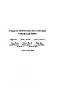
Fig. 1. P1520 reference model and the L-interface abstraction model.
each other and most of the time heavily dependent on the underlying networking technology and implementation, strong evidence point toward common features, that when put together as pieces of a puzzle they give rise to a picture that we believe is representative of the “programmable networks.” Recently such features have become the main focus of standardization activities and in particular the IEEE P1520 [3] and the IETF ForCES protocol working group [12]. In this paper, we are going to bring out and elaborate on a number of such features arguing that they are the ingredients that serve as building materials and principles to the next generation network element (NE) architecture enabled to realize the yet elusive rapid service deployment. The ingredients identified are the execution environment, the building block approach and the separation principle among the different operational planes necessary to support interoperability. Our analysis will draw from the state of the art and our experiences in working in the future active IP network (FAIN) EU project. We also argue that because of strong evidence regarding the versatility of the building block approach, there is a specific type of EE that is going to be dominant in the next generation of programmable networks assisted by the widespread adoption of network processors. As a result we are going to propose a new network element reference architecture that not only does it extensively uses this particular type of EE but also acts as a reference model to be used by service deployment mechanisms. Using this model we argue about the need for a configuration protocol for deploying service components in the network elements followed by its description. More specifically, in Section II, we review results from the two schools of thought, namely, the Opensig and in particular P1520 and ForCES, and the Active Networks followed by a discussion. In addition, we attempt to link P1520 with ForCES al-
though P1520 preceded ForCES but we argue that they both aim at the same objectives using very similar if not identical approaches. Section III, briefly describes the FAIN network element reference architecture that has been influenced by the two communities while focuses on one important feature, that of the execution environment (EE) and its particular type proposed by FAIN. In Section IV we describe the new configuration protocol. Finally, Section V summarizes our conclusions and outlines the future work. II. TWO SCHOOLS OF THOUGHT IN PROGRAMMABLE NETWORKS A. Open Signalling 1) IEEE P1520: The original motivation behind Opensig networks has been the observation that monolithic and complex control architectures may be restructured according to a minimal set of layers where the services residing in each layer are accessible through open interfaces thus, providing the basis for service creation (composition). Eventually, a number of results out of the Opensig community were formalized by the IEEE Project 1520 standards initiative for programmable network interfaces and its corresponding reference model [3]. The IEEE P1520 reference model (RM) provides a general framework for mapping programming interfaces and operations of networks, over any given networking technology. Mapping diverse network architectures and their corresponding functionality to the P1520 RM is essential. The IEEE P1520 RM, depicted in Fig. 1, defines the following four interfaces. • CCM interface: The connection control and management interface is a collection of protocols that enable the exchange of state and control information at a very low level between the NE and an external agent.
• L-interface: This defines an application program interface (API) that consists of methods for manipulating local network resources abstracted as objects. This abstraction isolates upper layers from hardware dependencies or other proprietary interfaces. • U-interface: This mainly provides an API that deals with connection setup issues. The U-interface isolates the diversity of connection set-up requests from the actual algorithms that implement them. • V-interface: It provides a rich set of APIs to write highly customised software often in the form of value-added services. CCM and L-interfaces fall under the category of NE interfaces, whereas U- and V-interfaces constitute network-wide interfaces. Initial efforts through the ATM sub-working group (P1520.2), focused on telecommunication networks based on ATM and introduced programmability in the control plane [13]. Later, The IP Sub-working group extended these principles to IP networks and routers. Fig. 1 also suggests a possible mapping of the P1520 RM to IP routers. However, their efforts focus on creating a generalized framework for designing interfaces not just for routers but also for any NE the core functionality of which is forwarding of traffic, e.g., switch, gateway etc [14]. For the remaining of this section we will focus on the activities of the IP working group as the most relevant to this paper. When the IP sub-working group (P1520.3) first met, they faced two critical questions: a) which of the interfaces of the RM is the most important one in terms of maximizing openness of the RM, and b) which is the right approach to achieve it. Eventually, they decided that NE interfaces (CCM and L) are the most critical ones as they abstract the functionality and the resources found in the NE, thereby, creating a kind of interoperability layer among different vendor’s equipment and most importantly, allowing the requirements of network services residing in higher layers to be mapped in many different ways onto the capabilities of heterogeneous NEs. The second question faced was the most complex one. Traditional packet and flow processing have long been the default network behavior. However, with increasing intelligence being pushed into NEs, emerging devices will perform multiple functions, thereby defining a new class of network elements that extend behavioral functionality within the network transport. Thus, traditional routers and switches are going to be subsumed with next generation NEs capable of dynamically adapting to multi-function requirements. They are expected to include address translation, firewall enforcement, advanced flow differentiation, proxy activation, load balancing, and advanced monitoring. Furthermore, in order to meet with the speed of the ever-rapid advancement in the technological frontiers, both in network devices and services/applications, an approach in specifying a standard should be based on a software architecture that allows extensive reusability of its modules. In other words, the development effort required to extend (i.e., proprietary or otherwise) the API should be minimized, so as not to hinder or delay deployment of emerging technological advances. The fundamental requirement levied on the standardization process of the API, is that the
standardization itself shall not interfere with the future advancement and development of related technologies. In other words, it is required to be extensible. Furthermore, the extensible nature has to be available at all levels of abstraction within the API hierarchy. The standard API has to be extensible to accommodate new network devices, while at the same time be able to accommodate newly developed network services and applications. The former includes, for example, a proprietary hardware mechanism to accelerate a particular functionality, which could be realized by software in a “conventional” IP router. Concluding, to make a standard extensible for keeping up with the pace of innovation and differentiation you must make the composition mechanism part of the standard thus enabling seamless extensions of the API in the future. Following this decision, P1520.3 also selected L-interface as their initial target for specification. In addition, the approach that was proposed to provide an answer to the second question is the building block approach [15], [16], which consists of three layers of abstraction that define a model for specifying the API (Fig. 1). The model enables network device programmability from two complementary perspectives, corresponding to an association with the layers of the L abstraction model, primarily service-specific and resource. This allows, for example, upper level interfaces to create or program completely new network services using generic resource abstractions or modify existing services using service-specific abstractions, which are themselves built on generic resource abstractions. The third layer is introduced to facilitate common device programmability by means of composition, via a standard set of base building block abstractions, which both the service-specific and resource layers are built. More specifically, the upper part of the L interface is the service-specific abstraction layer of the NE. The service-specific building block (SSBB) abstractions at this layer expose “sub”-interfaces associated with underlying behaviors or functions, state or policies on the local node that have concrete meaning within the context of a particular supported service (e.g., differentiated services). The idea here is that an administrator or Internet service vendor (ISV) need only program the device within the context of the service (i.e., preferably industry standardized), rather than deal with low-level abstractions associated with fundamental resources (e.g., scheduler, dropper) of the network device. Thus, to deliver the required service-specific behavior, he or she needs only modify, update or provision the service abstraction at the level that they understand or have a need (or privilege) to supplement. Alternatively, the middle part of the L interface abstraction model is the resource abstraction layer of the NE. The abstractions here are termed resource building blocks (RBBs), from which primitive behaviors (e.g., Diffserv PHB [8]) or new behaviors can be built. We envision the programmer is a sophisticated ISV developer or network software architect, who is aware of underlying resource abstractions (not implementation) of a NE (e.g., router), and can construct new behaviors or functions, change state or policies within the context of the generic abstraction, without specific knowledge of the underlying vendor device implementation.
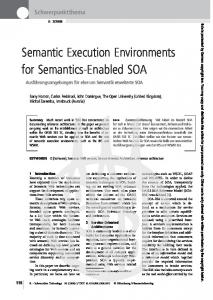
Fig. 2. ForCES architectural representation of NE.
The maximum degree of abstraction is achieved at the lowest layer of the abstraction model. It is at this layer that the composition mechanism is abstracted and becomes part of the standard. The idea behind the base building blocks (BBB) is to have abstractions that have no service or resource significance from a NE behavioral or packet processing perspective. These base blocks serve the needs of the programmer, only in an inheritance fashion such that the abstractions above the base layer (namely resource or service-specific) can be designed appropriately to create new functional service behaviors or resources or modify (enhance) existing ones in a consistent, standard object-oriented manner. As a result of the approach a number of APIs are defined at each layer with the ones at the BBB layer providing methods that allow RBBs to be composed in such a way that they form SSBB’s constructs. In this way, using the APIs of the BBB layers and defining as RBBs components like classifier, meter, shaper, queue, and scheduler, one can create a Diffserv SSBB the API of which will be the collection of the APIs of the individual RBBs. To this end, by standardizing a small set of RBBs one can create any SSBB that is required by specific network services. Alternatively, new RBBs may be introduced by means of inheritance from the BBB layer and deployed in the NE in order to support new network service requirements or enhance/extend existing functionality. 2) IETF ForCES: The Opensig community have long advocated the benefits of a clear distinction between control and transport plane. Recently, a working group of IETF, called forwarding and control element separation (ForCES) was formed with a similar objective to that of P1520, namely, “by defining a set of standard mechanisms for control and forwarding separation, ForCES will enable rapid innovation in both the control and forwarding planes. A standard separation mechanism allows the control and forwarding planes to innovate in parallel while maintaining interoperability” [12], [17]. According to [17], the NE is a collection of components of two types: control elements (CE) and forwarding elements (FE) operating in the control and forwarding (transport) plane, respectively. CE’s host controls functionality, like routing and signalling protocols, whereas FEs perform operations on packets, like header processing, metering, scheduling etc when passing through them. CEs and FEs may be interconnected with each other in every possible combination (CE-CE, CE-FE, and FE-FE) thus, forming arbitrary types of logical topologies (see Fig. 2). Every distinct combination defines a reference point, namely, , , and . Each one of these reference points may
define a protocol or a collection thereof, but ForCES protocol reference point. is only defined for the However, FEs do not represent the smallest degree of granularity of the NE functionality. Furthermore, as they implement the ForCES protocol they must facilitate CEs to control them in terms of abstracting their capabilities, which, in turn may be accessed by the CEs. It is at this point that the ForCES group faced a similar challenge as the IP working group in P1520 which they formulated it as follows: Since FEs may manifest varying functionality in participating in the ForCES NE, “the implication is that CEs can make only minimal assumptions about the functionality provided by its FEs” [18]. As a result, CEs must first discover the capabilities of the FEs before they can actually control them. The solution they suggest is captured in the form of an FE Model [18], while two of its requirements that must satisfy pertain to the problem of an extensible standard. The first mandates that the FE model should provide the means to describe existing, new or vendor specific logical functions found in the FE’s, while the latter demands to describe the order in which these logical functions are applied in the FE [5] In the ForCES FE model, they use a similar approach to the building block approach of the P1520.3 working group, by encapsulating distinct logical functions by means of an entity called, FE block. When this FE block is treated outside the context of a logical function, it becomes equivalent of the base building blocks. When someone looks what is inside every FE block then it becomes a resource building block. Similarly, FE blocks eventually are expected to form an FE block library—in principle extensible which will be part of the standard and the basis for creating complex NE behaviors, although dynamic extensions thereof, may be possible. Of course there are differences between the two initiatives but the main ideas are very close so we expect that in the future they will fully converge. A type of model like the FE model is useful when CEs attempt to configure and control FEs. ForCES has identified three levels of control and configuration, namely, static FE, dynamic FE, and dynamic extensible FE control and configuration. The first assumes that the structure of the FE is already known and fixed, the second one allows the CE to discover and configure the structure of the FE although selecting from a fixed FE block library, whereas the third one is the most powerful that allows CE’s to download additional functionality, namely FE blocks, onto FEs at runtime. Currently ForCES is mainly, focusing on the first level of control and configuration. B. Active Networks Active Networks transform the store-and-forward network into store-compute-and-forward network. The innovation here is that packets are no longer passive but rather active in the sense that they carry executable code together with their data payload. This code is dispatched and executed at designated (active) nodes performing operations on the packet data as well as changing the current state of the node to be found by the packets that follow. In this context, two approaches can be identified based on whether programs and data are carried discretely, namely within program and data packets (out-of-band) or in an integrated manner, i.e., in-band.
C. Discussion on the State-of-the Art
Fig. 3.
Active node architecture.
In the discrete case, the job of injecting code into the node and the job of processing packets are separated. The user or network operator first injects his customised code into the routers along a path. Then the data packet arrives, its header is examined and the appropriate preinstalled code is loaded to operate on its contents [19], [20]. Separate mechanisms for loading and executing may be required for the control thereof. This separation enables network operators to dynamically download code to extend node’s capabilities, which in turn they become available to customers through execution. At the other extreme lies the integrated approach where code and data are carried by the same packet [21]. In this context, when a packet arrives at a node, code and data are separated, and the code is loaded to operate on the packet or change the state of the node. A hybrid approach has also been proposed [22]. Active networks have also proposed their own reference architecture model [23] depicted in Fig. 3. According to it an active network is a mixture of active and legacy (nonactive) nodes. The active nodes run the node operating system (NodeOS) –not necessarily the same, while a number of execution environments (EE) coexist at the same node. Finally a number of active applications (AA) make use of services offered by the EEs. The NodeOS undertakes the task of simultaneously supporting multiple EEs. Accordingly, its major functionality is to provide isolation among EEs through resource allocation and control mechanisms, and providing security mechanisms to protect EEs from each other. It may also provide other basic facilities like caching or code distribution that EEs may use to build higher abstractions to be presented to their AAs. All these capabilities are encapsulated by the Node interface through which EEs interact with the NodeOS. This is the minimal fixed point at which interoperability is achieved [24]. In contrast EEs implement a very broad definition of a network API ranging from programming languages to virtual machines like the Spanner VM in Smart Packets and bytecodes, to static APIs in the form of a simple list of fixed-size parameters etc [25]. To this end, EE takes the form of a middleware toolkit for creating, composing and deploying services. Finally, the AN reference architecture [23] is designed for simultaneously supporting a multiplicity of EEs at a node. Furthermore, only EEs of the same type are allowed to communicate with each other, whereas EEs of different type are kept isolated from each other.
The purpose of the state-of-the-art presented in this paper is not to provide a thorough analysis and evaluation of programmable networks 1 but rather to identify those ingredients that may serve as building materials and principles to the next generation NE architecture. First and foremost, we consider the concept of EE as the basis of the next generation NE architecture that greatly facilitates the definition of a reference architecture. Such architecture acts as a reference point that service deployment algorithms need in order to make decisions about where service components can be deployed, which is the appropriate implementation technology of these components, how the deployed components are linked with existing ones that are running in the NE etc. But what exactly is an EE, what elements is it comprised from and are these elements part of the architecture or part of its chosen implementation? Furthermore, is it possible to identify specific types of EEs that are implementation independent? In the literature we can trace a variety of answers regarding the exact characteristics of an EE. Conceptually, an EE is the active network’s programming environment [26] when instantiated it becomes the runtime environment of a process or a process itself [27]. This programming environment may be centred on a particular language and may export some API that encompasses elements like a Java Virtual Machine [23], [26], toolkits used for building AAs (services) [19], [27] or even interfaces to access generic services that AAs may customise building value added services. EEs have also been proposed as extensions of the NodeOS for those that are allowed to be extensible [24]. The latter has an impact on where to draw the boundary between EE and NodeOS known as the node interface. The fact that the AN reference architecture [23] simultaneously supports multiple EEs, implies that EEs are also treated as principals based on which authentication, authorization and resource control takes places. Services and users that use an EE are represented by this principal, which is the only valid entity allowed to access NodeOS facilities. To this end, the EE concept is overloaded with the characteristics of a virtual environment. Prototypes proposed in [28], [29] may be interpreted in this way. Finally, EEs have been characterized not by the choice of technologies but rather by the services they offer and the architectural plane they operate at, namely, control, management, and transport [30], [31]. The boundaries between architecture and implementation are sometimes blurred that, in turn, makes it is very difficult to come up with a clear definition of an EE. Lack of an unambiguous definition impedes any effort to propose a reference NE architecture that not only does it encompass most of the research efforts so far, but also it is instrumental in designing a middleware for service creation and deployment. We are going to deal with this issue in Section III. The second of these ingredients is the right approach based on which EEs must be designed. As it has been argued, the approach must satisfy the requirements for composability, extensibility, and vendor independence. We believe that the building 1A thorough analysis and comparison of programmable networks may be found in [7] and [11].
Fig. 4. FAIN NE reference architecture.
block approach is the right one for designing EEs. Recently, a new research activity has been reported in [32] which uses a similar approach applied to redesign of protocols that do not imply a layered IP architecture. The final ingredient mainly deals with the problem of interoperability and the NE itself. It comes in the form of the separation principle among the different operational planes and the abstraction of the functionality at each one of the planes by means of open interfaces. III. FAIN NE REFERENCE ARCHITECTURE The FAIN NE reference architecture depicted in Fig. 4 describes how the ingredients identified previously may synergistically be combined in building next generation NEs capable of seamlessly incorporating new functionality or dynamically configured to change their behavior according to new service requirements. One of the key concepts defined by the FAIN architecture is the EE. In FAIN, drawing from an analogy based on the concepts of class and object in object-oriented systems, we distinguish EEs between the EE type and the EE instances thereof. An EE type is characterized by the programming methodology and the programming environment that is created as a result of the methodology used. The EE type is free of any implementation details. In contrast, an EE instance represents the realization of the EE type in the form of a runtime environment by using specific implementation technology, e.g., programming language and binding mechanisms to maintain operation of the runtime environment. Accordingly, any particular EE type may have multiple instances while each instance may be based on different implementations. Such distinction allowed us to address the issue of the principles that must govern and the properties that must be possessed by next generation NE’s, from the issue of how to build such systems.
The programming methodology that was used as part of the FAIN EE type was the building block approach according to which services break down into primitive, distinct blocks of functionality, which then may be bound together in meaningful constructs. To this end, services can be rebuilt from these primitive forms of functionality, i.e the building blocks, while building blocks may be reused and combined together in a series of different arrangements as this is dictated by the service itself. The result of this process is the creation of a programming environment like the one depicted in Fig. 5. In FAIN we have built two different EE instances, a Java EE and a Linux kernel-based EE, of this particular EE type [33]. FAIN architecture also allows EEs to reside in any of the three operational planes namely, transport, control and management while they may interact and communicate with each other either across the planes or within a single plane. In fact, it is not the EEs that communicate but rather distributed service components hosted by them part of deployed network services which can be accessed by applications or higher level services by means of the network API they export. EEs (instances) are the place where services are deployed. Services may well be extensible in the sense that the programming methodology and the corresponding environment (EE type) support service extension while they can access services offered by other EEs to achieve their objectives and meet customer demands. For example a service uses the code distribution mechanism to download its code extensions. The extension API then becomes part of the overall service interface. Furthermore, FAIN separates the concept of the EE from that of the virtual environment (VE). We argue that the concept of an EE as defined previously and that of a VE are orthogonal to each other. In fact a VE is an abstraction that is used only for resource management and control. Therein, services may be found and interact with each other. From the viewpoint of the operating system, the VE is the principal responsible for the consumption and use of resources, the recipient of sanctions in the event of policy violations and the entity that is legal to receive authorization when services accessing control interfaces. Similar conclusions may be found in [28], [29]. In other words, a VE provides a place where services may be instantiated and used by a community of users or groups of applications while staying isolated from others residing in different VEs. Within a VE many types of EEs with their instances may be combined to implement and/or instantiate a service. Another property of the reference architecture is that it makes no assumptions about how “thin” a VE is. It may take the form of an application, or a specialized service environment, e.g., video on demand, or even a fully-fledged network architecture as proposed in [30], [31]. Finally, a VE may coincide with an implementation (EE instance) that is based only on one technology, e.g., Java technology. In either case this is a design decision dictated by customer requirements and/or the VE owner. Out of all the VEs residing in a node there must be a privileged one that is instantiated automatically when the node is booted up and serves as a back door through which subsequent VEs may be created through the management plane. This privileged VE should be owned by the network provider, who has access rights to instantiate the requested VE on behalf of a customer through
Fig. 5. EE type: The programming environment.
a VE Manager (VEM). From this viewpoint the creation of VEs becomes a kind of meta-service. The other major and most important component of the reference architecture is the NodeOS. It offers all those facilities 2 that are necessary to keep all the other components together, and provides resource control, security, management, active service provisioning (ASP) of service components, and demultiplexing. More details may be found in [33], [34]. All these facilities in the NodeOS cooperate to deliver the overall functionality of the NodeOS to achieve its goals. Between VEs and NodeOS lies the node interface that encapsulates all the capabilities offered by the NE. Its objective is to create programmable abstractions of the underlying NE resources, whereby third-party service providers, network administrators, network programmers or application developers can exert or extend node control through the use of higher-level APIs. This interface coincides with the L-interface and its specification must be implemented by EEs in order to achieve interoperability among different NEs. Finally, between the NodeOS and the hardware NE there might be the open router interface. Its scope coincides with the scope of the CCM interface of P1520. The FAIN reference architecture is the starting point from which a detailed node architecture specification follows. Accordingly, it is complemented by the system architecture requirements, design and specification. This, together with customer/user/application requirements determines the degree of programmability to be built in the NE and the choice of technologies. The previous two ingredients, namely the EE instances and the open interfaces require a NE to reside in. Packets arriving at the node have to follow different data-paths inside the node. At every part of the node, EEs have been instantiated implementing the programming methodology of their corresponding EE types with some of them creating component-based programming environments. This gives rise to a new generation of 2We use here the word facilities to refer to services offered by the NodeOS to VEs and distinguish from services found inside EEs.
network elements with architectures that are component-based. Such trend has been accelerated by the advent of innovative network products like the network processors (NP), which are capable of hosting an EE without the cost of performance degradation. Fig. 6 depicts this new situation in the form of a possible NE representation. In FAIN we have designed and built a prototype of an AN node that adopts the scenario above. Instead of an NP we have built one EE at the kernel space and another one at the user space. Both EEs support the building block approach and receive packets, which are then directed to specific components as part of their data-path NE traversing. More detailed description may be found in [33]. A. Discussion on FAIN The FAIN NE reference architecture serves as a way to manage and control overall service deployment. Based on the ability to combine different EEs as part of the service creation and deployment not only may specific service components be deployed but also the whole programming environment (EE instance) which is bound with existing EE instances. To this end, different functional models may be mapped onto the same physical NE infrastructure. One example could be that an EE instance is deployed in an NP while another is represented by an ASIC. This constitutes a departure from the active networks reference architecture where only EE instances of the same type are allowed to communicate. Furthermore, the separation between VE and EE allowed us to separate the resource control from the specifics of a technology used by EEs as well as multiple EEs may be hosted by one VE and still being able to allocate resources as these are assigned to VE. Returning back to the ForCES working group and in particular their architectural representation of an NE built around the CEs and FEs as well as the proposed FE model [18], it is clear that the EE definition in FAIN is also valid for an FE definition
Fig. 6.
Network element representation.
as inferred from the current state of the IETF working group. In addition, an EE that resides in the control plane may well represent CEs since such control EEs are used for controlling EEs in the transport plane. Accordingly, the issues of FE control and configuration, especially those that pertain to dynamically extensible FE’s, are identical with those in FAIN. As such the mechanisms for service deployment built in FAIN which facilitate configuration and control of EEs (in the transport plane) may also be used for the same purposes within the context of the ForCES activity. For realizing the full interaction between control and transport plane EEs, or in other words constructing (configuring) data-paths by binding together service components, a new protocol is needed. The description of such a protocol is the subject of the remaining paper. Fig. 7. Data-path graphs in EEs across different layers. FOR CONFIGURING IV. ACTIVE P EXECUTION ENVIRONMENTS ROTOCOL3
In the FAIN network, the active NEs, and, in particular, EEs, execute programs representing universally identified modules, which interact with the received packet or the NEs environment. The active nodes decide, which programs should be executed and in which order to the received data packets by checking processing requests either carried by the packet itself (in-band) or submitted previously (out-of-band). As a result, the NE analyzes and evaluates the request in order to configure the EE by means of creating the data-path that encompasses the requested processing modules in the right order. The proposed protocol captures the semantics of configuring EEs of type like the programming environment depicted in Fig. 5. A. Graph-Based Processing A graph is a finite set of nodes (also known as vertices) connected by links called edges (or arcs). Throughout this paper we imply a general graph whose nodes are the processing 3Note
that a European patent for the new protocol by Hitachi
modules (service components) that will be acting on the active packets and the edges denote bindings between these modules. A data-path of an EE may be represented by means of an acyclic graph that shows the particular way that service components are connected (Fig. 7). This has implications on the possible ways that the graph may be traversed and defines the overall behavior of the data-path. Some steps can be done in sequence while others can be done in parallel. A packet may select a particular route within a graph or a number of different routes. The graph may also act as a policy in the sense that specific processing must take place either in a specific order or between components that are not directly connected, e.g., if a graph node indicates a decryption action and another one “virus scanning” it is clear that we have to first decrypt the incoming flow and then use the virus scanner. Data-paths are instantiated in EEs while service components of a data-path may belong logically to different layers, e.g., link layer, network layer, application layer (Fig. 7). To this end, the data-path may span across multiple conventional layers. This has also been lately advocated in [32]. Accordingly, the datapath has become the primary abstraction, which at the EE level
Fig. 8. Active packet taxonomy.
binds together service components by means of a graph. As a data-path may not be confined within an EE but may span the whole NE and eventually the network (end-to-end data-path), we can also generalize the concept of the data-path by creating a hierarchy whereby the data-path at the next level (NE level) is the concatenation of data-paths of the lower level (EE level) (Fig. 6). To this end, graphs may be composed of simpler ones and can be combined to specify end-to-end services in a platform independent way. Using graphs to specify services allows us to dynamically deploy them through reference. For instance an arriving packet may carry a reference to a graph, which can be deployed before processing this packet, or others that follow. Realising a graph requires a mapping between the topology thereof and the capabilities of the network or the NE. For this we need a model similar to the FAIN reference architecture or ForCES. In FAIN we have created a service deployment architecture that supports this functionality [34]. A data-path (graph) in theory can span several EEs hosted in the same or different NE’s, bus since we haven’t fully investigated the implications that arise in such an environment, we consider (without evident loss of generality) in the rest of the paper that the “graph” keyword is equivalent to data-path, which in turn, is confined within an EE. B. Processing-Based Taxonomy of Active Packets Active code is encapsulated within the active packet and can either be miniature programs or pointers to executable code that has to be fetched and executed. Via the program execution, the packet data may be modified or not. Based on this fact, as well as on the way a packet is processed, we have come up with the taxonomy depicted in Fig. 8. An active packet may be processed by the active NE (Type I) or passively forwarded to the next hop without processing (Type II). The later is a typical case for active packets that cannot (or are not intended to) be processed by the specific NE, e.g., encrypted packets, and is the default action for nonactive (legacy) packets. We further categorize the packets to i) Type I(A) if their process results in payload change and to ii) Type I(B) if this doesn’t happen. Once the packet processing decision is taken, we can have single processing where only one module will op-
erate on the packet and its data (this is the simplest case), or multiple processing where several modules will operate on the packet. Finally the processed packet according to one of the methods mentioned above may have its payload changed or not. The multiple processing is done conditionally, based on a path in a graph that provides the interconnections between the components that process the packet. The graph-based processing introduces a dynamic way of packet processing, which can be sequential, parallel or even mixed (arbitrary) multiple processing. In sequential multiple processing (SMP), the packet is processed by multiple program modules sequentially, while the processing order may or may not be important. In contrast, the parallel multiple processing (PMP) as its name implies, allows several program modules to operate on the packet in parallel, thus, resulting in less overall processing time. Here the order with which program modules operate on the packet is not usually important and this is the typical case where several modules need to process the same packet. In parallel processing, one can clone the packet at some point, distribute it to the appropriate modules and discard the clones once the processing has been done. The last implies that the incoming packet will not be modified by any of the processing modules (or at least at the part of the graph where this parallel approach will be applied). Finally the mixed multiple processing (MMP) is a graph that has several steps of which some can be done in parallel and some other sequentially. MMP is the most challenging due to the possible high complexity of the graph, but also the most interesting as we will be able to apply graph theory algorithms and always seek the optimal way to find the best paths within a graph (optimal processing of a packet). The graph-based approach allows us to decide which one of all possible component combinations is optimal for configuring our EE. The graph that describes the binding of processing modules that will process the packet can be carried by the packet or be selected from the available combinations of modules the active NE offers (the packet instead of a graph description carries a reference to the specific graph). Please note that this approach is technology independent, i.e., only the name of the components (service) and the way components are connected is described. The enforcement of the graph in the NE implies the existence of a functional entity in the node that maps the technology independent graph to a technology dependent one. This is possible, since this functional entity knows exactly the EE instance that has been deployed in the NE and the binding mechanism that applies to it. Accordingly, it will fetch the right implementation of the requested component for this particular EE instance, load it, and bind it with the other components, thus configuring the EE according to the request. In order to use this approach, we must have an a priori knowledge of the existing graphs (know what processing we want to apply to the packet) or dynamically discover it once the packet is on the NE. Furthermore we need a global namespace for the graph and its elements (the processing modules), be able to discover which modules are present to the NE and describe their binding (graph) in an appropriate representation (e.g., GraphML [43]). Finally we need a graph evaluation scheme to check the graph correctness and its implementation (instantiation/binding of the required modules) as well as
an optimization scheme in order to select the optimal path. In FAIN we have designed and implemented such an entity, called service creation engine (SCE), which performs this operation [34]. The arrival of the packet at the NE, signals the graph selection. If the NE is not aware of the graph, its semantics need to be downloaded. What follows is the graph evaluation, i.e., we have to check that the necessary hardware and software perquisites are there, that the components requested by the graph can indeed be bound and then if everything is in place, the packet process can start. In our implementation we have taken the simplest case of multiple processing, i.e., the sequential multiple processing and a single static graph in order to start experimenting. Ongoing FAIN work will expand the ideas presented here to a fully-fledged graph deployment and evaluation as a proof of concept. C. Multiple Packet Processing Methods FAIN envisions that future network elements will be comprised of multiple heterogeneous Execution Environments that operate at high speeds based on complex computational models. The multiple processing approach is the most challenging and we focus on this. The single processing approach is a subcase of multiple processing as it assumes that only one module will operate on the active packet, and it is what most of today’s active network architectures in practice do. The processing can be done in three different ways: In the first the packet is agnostic of the computation that will be applied to it, in the second the packet provides instructions on how its payload may be processed, and in the third we use a combination of the other two, i.e., we transform a non active flow to an active one by attaching to it the necessary headers in order to be handled as an active packet on which single or multiple processing can be applied. More specifically we have: 1) A Priori Binding of Processing Components: In this method, the binding between the various components that will perform the computations on the received packets is done before the flow arrives. Since we have a priori knowledge of the arriving flow, we are able to optimize the processing (e.g., specific algorithms selection) based on the characteristics of the flow. The approach is inflexible for standalone packets but the processing speed can be very fast for persistent flows, since the path for multiple processing is already fixed when data arrives to the NE. In this approach the network manager has pre-configured the EEs of the active NE (has selected the path in the graph that will be applied in order to process incoming packets) for specific tasks and the packets that arrive are agnostic about their payload handling from the NE side. In this approach the packet doesn’t need to refer to the graph that will be used for its processing as a default selection already exists, or the administrator of the active NE may even discard any such references and use its own graphs (binding models) to process any incoming packets, if the graph proposed by the packet is not in its allowed graph lists (graph selection based on policy). The last can be done in order to avoid specific graphs, e.g., that are NE-safe but not network-safe. 2) A Posteriori Binding of Processing Components: In this method there is no active NE preconfiguration, as the packet
carries all info (including the graph or references to the graph) that instruct the active NE how to process the packet. Specifically the packet can carry a reference to a graph that implies a list of processing requests from specific programs that reside in the NE or are fetched and loaded on demand. The binding of these programs is done in real time and their execution takes place after of course the packet arrival. This approach allows the execution of different multiple processing requests in each data packet explicitly, which gives full customization on per packet basis, therefore maximum flexibility but probably with the cost of higher computation and less performance. The distinction between a priori and a posteriori approaches is one of perspective, primarily useful as a basis of comparing two ways of thinking about configuring EEs and setting up datapaths. Accordingly, one can use a posteriori binding in the form of a control active packet to enforce a graph and setup the flow that will be processed later by the NE upon arrival. 3) Hybrid Binding of Processing Components: The third method is a hybrid one as it combines both approaches mentioned before in the following sense. The graph based on which the packet will be processed has already been enforced in the NE and associated with the flow that this packet belongs to (e.g., distributed by the network manager) as described in the a priori method. However, the packet also carries in its header an “Internal header” that allows the packet, or the sub-flow that it represents, to further customise its graph at runtime, for instance by avoiding some of the processing modules in the graph by selecting a different path. To this end, the data with the attached Internal header (whose visibility is local on the NE or the local network) is processed on per packet basis as described in the a posteriori method. With this approach we increase the granularity of customization in the NE, therefore offering higher levels of flexibility and programmability. Another benefit is that it allows us to “activate” passive flows (by encapsulating them as active packets and assigning a default path within a graph), therefore providing a smoother migration from passive to active networks. Of course here we have some extra overhead because not only we need mechanisms for routing the packet into multiple processing components, but we also need mechanisms for assigning the internal header (and eventually remove it when its usage ends) to the arriving packet data. D. Extending ANEP A new protocol that configures component-based EEs is required to encapsulate the semantics and the operations described in Sections IV-A and C. Today there are two dominating protocols in active networks namely the active packet encapsulation protocol (ANEP) [36] that is widely used in the ABONE testbed [40] and simple active packet format (SAPF) [41]. ANEP specifies a mechanism for encapsulating active network frames for transmission over different media, e.g., an existing IPv4/IPv6 [39] network infrastructure or transmission over the link layer. It also allows coexistence of different execution environments 4 and proper demultiplexing of received 4Here the term execution environment is used according to the definition that emerges from Section II-B which may be different from the FAIN definition of Section III.
TABLE I DEFINED OPTION TYPE
TABLE II GENERAL IDENTIFIER FORMAT
packets. We have selected ANEP to configure EEs in order to act on active packets, e.g., perform multiple processing. This was done because SAPF, due to its simplicity, doesn’t allow specifying multiple processing components to act on the packet. In contrast, ANEP allows us to define a new option data format, thus encapsulating the proposed extension that covers our goals, i.e., execute multiple processing. We used the ANEP Option Format to define our own format. For the Type ID field value of the ANEP packet format we used the value 10 651 as the FAIN type ID. This type of ID implies a FAIN network with the architecture depicted in Fig. 4 rather than an EE according to the intentions of the original ANEP protocol. To this end, FAIN and ABONE can only interoperate via a gateway that will perform the necessary adaptations. It must be noted, that our proposal in this paper describes a general mechanism for configuring the emerging types of componentbased EEs that provide multiple processing on packets and we treat this extended version of ANEP as a mean to implement and experiment with this mechanism. To this end, the same approach may be adopted by another protocol, e.g., ForCES, to achieve the same objective. Table I shows a list that includes the currently proposed option formats in FAIN and their temporarily assigned values. Since the global Option Type values are assigned by active networks assigned number authority (ANANA) [42], new numbers should be assigned for global use. The general format for all types of identifiers that we use is depicted in Table II. All three identifiers within FAIN, i.e., The virtual environment ID, the execution environment ID and the taxonomy ID can be mapped to this general format. 1) Virtual Environment (VE) Identifier Option: The VE identifier (format depicted in Table II) option is a must when the type ID in the active packet header is an identifier for FAIN active packets (i.e., has a value of 10 651). The option type field is the value of option type virtual environment identifier. The option type value is 101 indicates that the option value is that of the VE ID to which this packet belongs to ( in Table II). The Option Length has a fixed value of two words
(one word for the header and one for the payload of this option is the identifier indicating type). The 32-bit VE ID the appropriate VE to which the active packets are dispatched. The network provider, who is the owner of the network, assigns through his privileged VE, a VE ID when a service provider (SP) requests from the network provider to create on his behalf a new VE. This value is carried by all packets originating from this SP. The value 0 is reserved for future use and value 1 is assigned for the privileged VE according to FAIN architecture and business model. 2) Execution Environment (EE) Identifier Option: The Execution environment (EE) identifier’s format is depicted in Table II. Similarly with the VE identifier option, the option type field is the value of option type execution environment identifier. When its value is 102, the option becomes the value of the EE ID that this packet will be processed by. The option length has a fixed value of 2 words (one word for the header and one for the payload of this option type). The 32-bit EE ID is the identifier that identifies the EE to be configured or that will process the packet. This is an important field value that must be uniquely recognized throughout the network as it allows us to identify the execution environment, which implies usually its capabilities and possibly other info including technology and the platform used in every NE. Such information will be used by the functional entity that enforces the graph during the configuration of the EE for selecting a compatible implementation of the service components to be deployed and linked in the EE as mentioned in Section IV-A. 3) Taxonomy Identifier Option: A taxonomy identifier is defined in order to apply the categorization depicted in Fig. 8. Table II shows an option format for taxonomy ID. The option type value for the taxonomy identifier is 103 within FAIN. The option length value is 2 in 32 bit words (4 bytes). A possible mapping of our categorization in the taxonomy ID of the protocol defined here can be as follows. • Bit 0: It shows how to handle the packets when a NE does not recognize the VE/EE ID. If the bit value is 0, the active NE tries to passively forward the data, and if the bit value is 1, the NE simply discards them. • Bit 1: It shows whether active packet has an option data (bit value is 1) or not (bit value is 0). • Bit 2: It shows whether active packet’s data need processing (bit value is 1) or not (bit value is 0). This bit classifies the packet as Type I or Type II. As an example, a packet processed by more than one EEs will be submitted to the first EE who will process it and then resubmit it to the classifier so that it can be forwarded to second EE. • Bit 3: It shows whether active packet’s data, after the processing, are changed (bit value is 1) or not (bit value is 0). This bit classifies the packet as Type I(A) or Type I(B). • Bits 4–31: These bits are used in order to refer to the way the processing will be done. As an example one could map each these 28 bits to a different processing module (limiting us to 28 components which is inadequate) or even better map them to a graph that will show how the processing is done (number of processing modules, conditional processing, parallel or single steps etc). The later
TABLE III MULTIPLE PROCESSING OPTION HEADER
TABLE IV FLOW IDENTIFIER
can imply different graphs to be selected per packet if each combination of the 28 bits is mapped to a unique graph. Please note that in our efforts up to now we assume the simplest cases in order to experiment with the approach. Therefore we assume that each packet can select one graph that fully describes how the packet can be processed. Having been through the graph-controlled processing, the packet is directed to the output port. However, more complex processing can be done and this will give the graph theory area a field to apply its findings. In a more advanced scenario some bits are used to indicate that graphs need to be applied in order to process the graphs can be done packet, if some steps related to in parallel or if there is a dependency between them etc. We expect that research toward this direction will come up with optimal algorithms for processing packets that will take full advantage of software and hardware capabilities within the active NE. Furthermore it is clear that a namespace is required where graphs and the respective processing algorithms can be uniquely identified. 4) Multiple Processing Identifier List Option: Multiple processing allows several modules to operate at least once on the packet’s data. The order based on which they operate on the packet is defined by specifying the path within the graph that is selected for multiple processing. Therefore a new protocol must include a list of multiple processing requests, i.e., point to the graph(s) that will be used to process the packet and their respective paths (which can be different from the default ones). In order also to have a status of every processing, i.e., to detect which processing has already been done, the new protocol must include the status of each processing request. A graph composed of nodes reveals that modules will need to operate on the packet. Also, in order to detect the length of both processing list and status bits, the appropriate fields should be included in the protocol. Table III shows the proposed option header format for executing multiple processing. When the multiple processing identifier list option data is set, the NE executes multiple processing to the active packet data along the order of the list. The option type field value for multiple processing is 104 in FAIN. The option length field value is defined depending on the number of multiple processing requests. The 16-bit long number of multiple processing field value shows how many processing requests exist and the length of status bits indicates the
length of status bits written in 32 bit words (4 bytes). The list for status bits of each processing is used if a processing request exists (in other words, if the value of the number of processing requests is not zero). The status of each processing request is shown in this field, i.e., each bit shows whether processing is executed or not. If the number of multiple processing is not multiple of 32 (bit), the length of this field must be aligned by filling it with zeros. Finally, the processing ID value reveals the identifier for executing processing. The data are listed up depending on the number of multiple processing. Each such field is 16 bits long. Since the new option header includes the list of status bits corresponding to each processing, it’s easy to detect if a processing is completed or not. In addition, it might be possible to further apply optimization algorithms depending on the local configuration. Optimization is achieved by the selected graph, but if the NE has special conditions, e.g., two same modules implemented in different languages with different capabilities (e.g., hardware support for one and software only for the other) and different performance exist, it might be of benefit to use both modules on demand (hardware version for high speed and the software version for low priority requests). The last makes also possible to realize execution of multiple processing requests in different program languages belonging to heterogeneous EEs, as the new option header includes only the list of processing IDs that should be executed (possible order is defined by the graph). For realising this, the data is only transmitted based on the Processing ID similar to data transmission based on the IP port number. 5) Flow Identifier Option: The flow identifier for IPv4 address (format depicted in Table IV) includes a source IP address (32 bits), a destination IP address (32 bits), a source port number(16bits), a destination port number (16 bits), a protocol number (8 bits) and zero stuffing (24 bits). This flow definition is used for easier identification of the flow to be processed. 6) Example of Multiple Processing: Fig. 9 shows an example of multiple sequential processing. The extended ANEP options we mentioned in Sections IV-D-I–V indicate via the selected graph that the packet data should be processed by and two processing modules, i.e., the virus check modules. The path (module1 the compression module2) of the graph (graph’s nodes are 1, 2, and 3) is written in the multiple processing identifier list option of the first ANEP packet data. In this case, the option data is sent to the component binding manager who after evaluating the graph path and verifying that the proposed component binding described is feasible, binds the virus check component and compression component, in order to execute multiple
Fig. 9. Example of multiple processing.
processing to the specified flow. When the active NE receives the flow packet, it follows the path and as a result the virus check and compression processing are executed and process the packet data (depicted as flow(I) in Fig. 9). Similarly by selecting another path in the graph (graph’s nodes are 1, 2, and 3) or another graph (subgraph’s nodes are 1 and 3) one could and encryption bind the virus check component (depicted as flow(II) in Fig. 9). However, if a packet proposes a graph that attempts to bind the compression and encryption components, the binding manager evaluation of the graph will reject this attempt as in its graph this path cannot be constructed. V. CONCLUSION As we are moving toward a global network engineered to carry and integrate a variety of services, programmability in the network is becoming more than ever important to the degree that we now talk about programmable networks and even the programmable Internet as the next generation network. In such a distributed computing infrastructure one can control all aspects of the distributed computing model. With this background, different research initiatives and fora were formed with the fundamental objective of realizing the yet elusive rapid service deployment, and have successfully created various networking architectures, concepts and technologies. Furthermore, a specific type of execution environment is emerging whereby additional processing is injected by means of service components. Such types of EEs allow network elements to be dynamically extended with additional functionality customised for specific services. In this paper, we proposed the FAIN reference architecture where we argued and described the way that amalgamates earlier efforts of the research community, ranging from Opensig, ForCES, and active networks. The FAIN architecture was de-
signed so that it can not only extend the outcome of these seemingly different initiatives, but can also use them in a synergistic manner to build programmable networks. The key architectural property of FAIN is flexibility, and in particular composability and extensibility. It has been achieved by clearly distinguishing the EE between the EE type and the EE instances, while introducing the VE as a place in which many types of EEs with their instances may be combined to implement and/or instantiate a new service. The EEs can reside in transport, control and management planes, and with the introduction of the new data protocol that can flexibly configure multiple EEs, services can be composed in a multi-EE and multi-processing manner. We have also shown, that FE’s in ForCES are very similar in nature and purpose with EEs in FAIN, and as such the protocol proposed here may well be used for their configuration. Though we have designed and partly implemented the FAIN reference architecture and the new data protocol, much work is still ahead in order to realize a fully functional programmable Internet. In the architectural aspect, we need to design the inter-EE model such as the data path among the EEs. As for the data protocol, we need to implement the frameworks of the processing components as well as the protocol stacks for end-user terminals, and also perform extensive evaluation of the protocol itself. In the mean time, we are planning to evaluate how other emerging technologies, such as the network processors, can be effectively applied to the FAIN architecture. ACKNOWLEDGMENT The authors would like to acknowledge all FAIN partners and J. Vicente for his contribution to the P1520.3 working group, and in particular, for the long discussions and input in the building block approach. The authors would also like to express their gratitude to the reviewers for their valuable comments.
REFERENCES [1] (1996) DARPA Active Network Program. [Online]. Available: http://www.darpa.mil/ato/programs/activenetworks/actnet.htm [2] Open Signalling Working Group. [Online]. Available: http://www. comet.columbia.edu/opensig/ [3] J. Biswas et al., “The IEEE P1520 standards initiative for programmable network interfaces,” IEEE Commun., vol. 36, Oct. 1998. [4] Requirements, Analysis and Overall AN Architecture FAIN Project Deliverable 1. [Online]. Available: http://www.ist-fain.org/deliverables/del1/d1.pdf [5] H. Khosravi and T. Anderson, Eds., (2003) Requirements for Separation of IP Control and Forwarding. [Online]. Available: http://www.ietf.org/internet-drafts/draft-ietf-forces-requirements-08.txt [6] N. Bjorkman et al., “The movement from monoliths to component-based network elements,” IEEE Commun., vol. 39, Jan. 2001. [7] A. T. Campbell, H. De Meer, M. E. Kounavis, K. Miki, J. Vicente, and D. Villela. (1999) A Survey of Programmable Networks. ACM Comput. Commun. Rev. [Online] [8] (1998) An Architecture for Differentiated Services. [Online]. Available: http://www.ietf.org/rfc/rfc2475.txt [9] Intel, IXP Family of Network Processors. [Online]. Available: http://www.intel.com/design/network/products/npfamily/ [10] IBM Network Processors. [Online]. Available: http://www-3.ibm.com/ chips/products/wired/products/network_processors.html [11] Initial Active Network and Active Node Architecture FAIN Project Deliverable 2. [Online]. Available: http://www.ist-fain.org/deliverables/ del2/d2.pdf [12] IETF ForCES. [Online]. Available: http://www.ietf.org/html.charters/ forces-charter.html [13] IEEE P1520.2, Draft 2.2, Standard for Application Programming Interfaces for ATM Networks. [Online]. Available: http://www.ieee-pin.org/ pin-atm/intro.html [14] B. Biswas et al.. (2000) Proposal for IP L-Interface Architecture, IEEE P1520.3, P1520/TS/IP013. [Online]. Available: http://www.ieee-pin. org/doc/draft_docs/IP/p1520tsip013.pdf [15] J. Vicente et al.. (2001) L-Interface Building Block API’s IEEE P1520.3, P1520.3TSIP016. [Online]. Available: http://www.ieeepin.org/doc/draft_docs/IP/P1520_3_TSIP-016.doc [16] J. Vicente, M. Kounavis, D. Villela, M. Lerner, and A. Campbell. Programming internet quality of service. presented at Proc. 3rd IFIP/GI Int. Conf. Trends Toward Universal Service Market. [Online]. Available: http://comet.ctr.columbia.edu/~campbell/papers/usm00.pdf [17] (2002) IETF ForCES, Draft-IETF-Forces-Framework-04.txt. [Online]. Available: http://www.ietf.org/internet-drafts/draft-ietf-forces-framework-04.txt [18] L. Yang, J. Halpern, R. Gopal, and R. Dantu, “ForCES Forwarding Element Functional Model,”, 2003. [19] D. J. Wetherall, J. V. Guttag, and D. L. Tennenhouse. (1998) ANTS: A Toolkit For Building and Dynamically Deploying Network Protocols IEEE Openarch. [Online]. Available: ftp://ftp.tns.lcs.mit.edu/pub/papers/openarch98.ps.gz [20] D. Decasper, G. Parulkar, S. Choi, J. DeHart, T. Wolf, and B. Plattner. (1999) A Scalable, High Performance Active Network Node IEEE Network. [Online]. Available: http://www.tik.ee.ethz.ch/~dan/papers/ ieee_ann_1.pdf [21] B. Schwartz, A. W. Jackson, W. T. Strayer, W. Zhou, D. Rockwell, and C. Partridge. (1999) Smart Packets for Active Networks OPENARCH’99. [Online]. Available: ftp://ftp.bbn.com/pub/AIR/smart.ps [22] D. Scott Alexander, W. A. Arbaugh, M. W. Hicks, P. Kakkar, A. D. Keromytis, J. T. Moore, C. A. Gunter, S. M. Nettles, and J. M. Smith, “The switchware active network architecture,” IEEE Network, vol. 12, pp. 29–36, May/June 1998. [23] K. L. Calvert, Ed., (1999) Architectural Framework for Active Networks Draft Version 1.0. [Online]. Available: http://protocols.netlab.uky.edu/ ~calvert/arch-latest.ps [24] L. Peterson, Ed., “Node OS Interface Specification AN Node OS Working Group,”, http://www.cs.princeton.edu/nsg/papers/nodeos02.ps, 2001. [25] K. Calvert, S. Bhattacharjee, E. Zegura, and J. Sterbenz, “Directions in active networks,” IEEE Commun., vol. 36, pp. 72–78, Oct. 1998. [26] J. M. Smith, K. Calvert, S. Murphy, H. K. Orman, and L. L. Peterson, “Activating networks: A progress report,” IEEE Comput., vol. 32, pp. 32–41, Apr. 1999.
[27] S. Berson, B. Boraden, and L. Ricciulli. (2000) Introduction to the ABone. [Online]. Available: http://www.isi.edu/abone/DOCUMENTS/ ABoneIntro.ps [28] J. E. van der Merwe, S. Rooney, I. M. Leslie, and S. A. Crosby, “The tempest—A practical framework for network programmability,” IEEE Network, vol. 12, pp. 20–28, May/June 1998. [29] M. E. Kounavis, A. T. Campbell, S. Chou, F. Modoux, J. Vicente, and H. Zhang, “The genesis kernel: A programming system for spawning network architectures,” IEEE J. Select. Areas Commun., vol. 19, pp. 49–73, Mar. 2001. [30] S. Bhattacharjee, “Active Networks: Architectures, Composition, and Applications,” Ph.D. dissertation, Georgia Tech., Atlanta, 1999. [31] B. Braden, A. Cerpa, T. Faber, B. Lindell, G. Phillips, J. Kann, and V. Shenoy. (2001) Introduction to the ASP Execution Environment (Release 1.5). [Online]. Available: http://www.isi.edu/active-signal/ARP/DOCUMENTS/ASP_EE.ps [32] B. Braden, T. Faber, and M. Handley. (2002) From Protocol Stack to Protocol Heap—Role Based Architecture. HotNets I, Princeton University, Princeton, NJ. [Online]. Available: http://www.cs.washington.edu/hotnets/papers/braden.pdf [33] Revised Active Network and Active Node Architecture FAIN Project Deliverable 4. [Online]. Available: http://www.ist-fain.org/deliverables/ del4/d4.pdf [34] Specification of Revised Case Study Systems FAIN Project Deliverable 5. [Online]. Available: http://www.ist-fain.org/deliverables/del5/d5.pdf [35] M. Raguparan et al.. (2000) L Interface for Routers That Support Differentiated Services IEEE P1520.3, P1520/TS/IP012. [Online]. Available: http://www.ieee-pin.org/doc/draft_docs/IP/p1520tsip012-1.pdf [36] The Active Network Encapsulation Protocol. [Online]. Available: http://www.cis.upenn.edu/~switchware/ANEP/ [37] FAIN—Future Active IP Networks. [Online]. Available: http://www.istfain.org [38] J. M. Smith and S. M. Nettles. (2003, ) Active networking: One view of the past, present and future. IEEE Trans. Syst., Man, Cybern.. [Online] [39] S. D’Alu, O. Festor, and E. Fleury. Active Network Encapsulation Protocol (ANEP) Extension for IPv6. presented at Work in Progress. [Online]. Available: http://alternic.net/drafts/drafts-s-t/draft-sdaluanep-ipv6-00.html [40] ABONE Testbed. [Online]. Available: http://www.isi.edu/abone/ [41] D. Decasper and C. F. Tschudin. The Simple Active Packet Format (SAPF). presented at Work in Progress. [Online]. Available: http://www.ifi.unizh.ch/ikm/abone/sapf/draft.txt [42] ANANA(Active Networks Assigned Number Authority). [Online]. Available: http://www.isi.edu/~braden/anana/ [43] GraphML. [Online]. Available: http://graphml.graphdrawing.org/ [44] A. V. Vasilakos, K. G. Anagnostakis, and W. Pedrycz, “Application of computational intelligence techniques in active networks,” in Soft Soft Computing. New York: Springer-Verlag, 2001, vol. 5, pp. 264–271.
+