Compositional modeling of complex systems: contact center scenarios in OsMoSys Giuliana Franceschinis1 , Marco Gribaudo2 , Mauro Iacono3 Stefano Marrone3 , Nicola Mazzocca3 , and Valeria Vittorini4 1
3
4
Dipartimento di Informatica, Universit` a del Piemonte Orientale, Piazza Ambrosoli 5, 15100, Alessandria, Italy,
[email protected] 2 Dipartimento di Informatica, Universit` a di Torino, Corso Svizzera 185/B, 10149 Torino, Italy,
[email protected] Dipartimento di Ingegneria dell’Informazione, Seconda Universit` a di Napoli, Via Roma 29, 81031 Aversa, Italy, {mauro.iacono,stefano.marrone,nicola.mazzocca}@unina2.it Dipartimento di Informatica e Sistemistica, Universit` a degli Studi di Napoli “Federico II”, Via Claudio 21, 80125 Napoli, Italy,
[email protected]
Abstract. In this paper we present the application of a compositional modeling methodology to the re-engineering of Stochastic Well Formed net (SWN) models of a contact center. The modeling methodology is based on the definition of proper operators to connect submodels and it is supported by the OsMoSys modeling framework. The paper describes the implementation of a library of reusable SWN submodels of the contact center components and the definition of proper SWN connectors to easily develop models of different configurations of the system. We also describe the solving process of the composed models and its integration in the OsMoSys framework. Moreover, we discuss the advantages that this approach, based on the definition of classes and instances of submodels, can provide to the application of SWN to complex case studies.
1
Introduction
Compositionality is an effective mean to cope with the complexity of real system modeling and analysis. It can also be exploited to set up a framework where designers, who may not be expert in formal modeling languages, compose models of complex scenarios by just choosing building blocks from a library and connecting them. The building blocks could hide complex models built by experts. In the context of Petri nets (PN) a number of proposals have appeared in the literature to add model (de)composition features to a formalism that is not compositional in its basic definition (e.g. [1, 3, 10, 11]). In particular, in [13, 14] PNs are used to describe the behavior of object classes and communication mechanisms are defined to allow the object models to inter-operate. The approach proposed in [7] adapts this model composition paradigm to Stochastic
Well Formed nets (SWN) by extending it with a client-server model composition schema, inspired by the Cooperative Nets approach [12]. Such composition schema is supported by OsMoSys, a multi-formalism modeling framework providing the mechanisms to define and apply composition operators and rules on the top of formalisms that are not compositional in their original definition. In this paper we present the application of a compositional modeling methodology to the re-engineering of the SWN models of a real contact center, and the work done to implement a library of reusable submodels, a feature that was considered as highly desirable in an earlier study on this application domain [6]. Both the contact center components modeling methodology and the implementation of a library of reusable building blocks, are based on the OsMoSys framework. The approach to modeling of contact center scenarios that we apply in this paper differs from the one described in [6] from two points of view: in [6] the composition was performed on low level operators, namely transition superposition, moreover the choice of the number of subnets to be composed, the labels assignment and the exact sequence of calls to the composer tool (Algebra) were all done manually, without any automatic support; in this paper instead higher level composition operators have been defined, that have the effect of better isolating the model of the components from the model of their interaction, as a consequence the correct configuration of the connection subnets and the needed sequence of calls to the composer tool can be automatically generated. This highly simplifies the task of generating different scenarios by a user with limited knowledge on the underlying formalism. In this paper we do not focus on the analysis phase and on the results that can be obtained, since they would be comparable to those already presented in [6], but rather on the advantages of the proposed methodology in promoting model reuse and in facilitating the composition task. An interesting next step would be to investigate the possibility of exploiting the model structure to improve the efficiency of the analysis phase through decomposition methods. With respect to the work presented in [7], message sending is used as communication paradigm (instead of client-server) and more complex connection operators are introduced to represent the communication sessions between the client and the site components of the contact center. The paper is organized as follows. Sect. 2 describes the contact center case study, Sect. 3 introduces the modeling approach and provides a brief introduction to the OsMoSys framework, Sect. 4 defines the set of operators used to build the compositional models of contact center scenarios and describes the SWN models of the contact center components. In Sect. 5 the automatic process that generates the final SWN model of the contact center scenarios is briefly presented. Finally, Sect. 6 discusses the advantages of the proposed compositional approach and highlights possible directions for future work.
2
Contact center scenarios
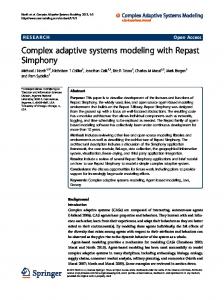
Contact centers are today an effective way for companies to manage client relationships and achieve some economical advantages, since they may lower post-sell assistance costs or allow companies to bypass usual distribution chains for selling products or services. Effectiveness and inexpensiveness of contact centers can only be exploited through a correct design and proper management policies. Sophisticated policies can require a very complex structure. Performances of a contact center can be evaluated by simulation of a proper model of their architecture. A correct model of a contact center architecture should be fed with incoming calls. Calls are generated by a client pool. A client pool is influenced by the kind of product or service the contact center offers and is a collection of customers, grouped in customer classes. Customers can be grouped by the level of quality of service they are entitled to, by behavior, by the service they access. It is thus necessary to capture a good client pool model in order to build simulation scenarios able to properly represent the real behavior of the contact center under evaluation. In our modeling technique, site classes are developed, as well as client pool classes, which are “glued” by connectors representing the communication infrastructure. In this work we present some models of client pools and different site architectures. Client pool models describe the behavior of customer classes and are characterized by several parameters; from another point of view they can be seen as workload generators for sites. Customers in a pool can be partitioned into classes with different privileges and/or different propensity for hang up. The classes can have different call generation rates, to describe different service needs, and different hang up rates. Sites are more complex. Customers always use a single policy: they need a service, they call the contact center, they give up or wait, they access the service or give up again, they leave the contact center. On the other hand, sites can implement different policies in order to obtain different QoS (Quality Of Service) classes for customer, they can have a variable number of queues, a variable number of operators per queue, service times that depend on the queue or the operator. Some queues could be specialized in handling some type of requests, or different maximum queuing times before discarding a waiting call. While client pools and sites are the basic components of our scenarios, connectors define how they can interact, and allow to define different contact center topologies. The communications between pools and sites follow routing and session handling rules, in other words they support the communication protocols used by clients and sites to interact. In this work message sending is used as the basis for implementing different protocols in a flexible way. Two protocols have been defined and modeled: the first, C2SP (Client to Server Protocol) is used in communications between a client pool (called in the following client for sake of simplicity) and a site (in the following server); the other, S2SP (Server to Server Protocol) in communications between sites. The C2SP is logically described in Fig. 1.
Two kinds of messages can be sent from the client to the server: the first (REQ) is used to initiate a communication session and request a service, the second (HUP) is used to drop the communication instantaneously (regardless of whether the service has been furnished or not). Two other messages can be sent from the server to the client: the first (NFY) signals the acceptance or the refusal of a request (REQ), the second (END) signals the correct end of a service. Services are considered as transactions in data bases: they are either completely supplied or not at all. A server receiving a request (REQ) can either accept it for service or not, depending on its instantaneous service capability. After the server accepts the request, the client can either wait for service completion or hang up the telephone without obtaining the service.
Client
Server REQ
in
out
{REQ , HUP }
NFY [dis ] Client
Server out
in
{NFY [acc |dis ], END}
Fig. 1: C2SP protocol
Client
Server REQ
Fig. 2: C2SP - Service denied
Client
Server REQ
NFY [acc ]
NFY [acc ]
END
HUP
Fig. 3: C2SP - Service accepted
Fig. 4: C2SP - Hang Up
Figures from 2 to 4 depict some possible sessions. In Fig. 2, a simple connection refusal is showed. In Fig. 3, a correct service session is showed. In Fig. 4,
the service request is accepted by the server, but the client interrupts the service by issuing a hang up signal (it asynchronously closes the communication).
Transferring Server
{RPL [acc |dis ], sNFY [acc |dis ], sEND }
Fig. 5: S2SP protocol
REQ
NFY[dis]
Asked Server
sREQ
RPL [dis ]
out
in
Asked Server
Transferring Server
{sREQ , PRG , MSG, sHUP }
in
out
Client
Fig. 6: S2SP - Transfer Failed
The example situations depicted in Fig. 3 and 4 show the importance of having message sending as a communication paradigm: in fact the protocol has been designed in order to be interrupted asynchronously in any phase with different behaviors. The S2SP is logically described in Fig. 5. It is used whenever a site cannot serve an incoming call for lack of resources as well in servicing units as in queues. When a server is in such a situation, it asks all other servers, using the request (sREQ) signal, if any of them is able to service the request: all servers reply with a RPL signal either accepting or refusing the request. If at least one answering server is accepting, a place for the incoming call is reserved in the queues of the first accepting server which notifies the acceptance using the RPL signal, while all other servers receive a purge (PRG) message. If no answering server is accepting, the call is lost. When a server receives a PRG, it drops the reservations it holds. The acceptor server receives a MSG signal carrying the original client request and answers the requesting server with a sNFY signal, analogous to the NFY signal in C2SP. The rest of the protocol uses the sEND and sHUP signals, like END and HUP in C2SP. Figures from Fig. 6 to Fig. 8 depict some possible sessions. Fig. 6 describes the situation in which a call is transferred to another server which does not accept it (for lack of resources). Fig. 7 describes an accepted call transfer. A situation where the client hangs up is illustrated in Fig. 8. An example of a simple complete session involving both protocols is given in Fig. 9. In this situation we have one client and four servers. The server connected with the client has no resources to handle an incoming call: it asks the other servers for a transfer. Two servers are available and the fourth refuses the request. One of the available servers receives the call for service while the other receives a PRG message in order to free booked resources. The service is completed by the ”winner” server regularly.
Client Transferring Server
Client REQ
REQ
Asked Server
Transferring Server
Asked Server
sREQ
sREQ
RPL [acc ]
RPL [acc ]
MSG MSG
NFY [acc ]
sNFY [acc ]
NFY
sNFY [acc ]
HUP sEND
END
sHUP
Fig. 7: S2SP - Transfer OK Client REQ
Transferring Server
Fig. 8: S2SP - Hang Up Asked Server 1
Asked Server 2
Asked Server 3
sREQ
RPL [acc ] RPL [acc ] RPL [dis ] MSG
PRG
sNFY [acc ]
NFY [acc ]
sEND
END
Fig. 9: S2SP - Call Transfer Accepted
Server
Client
Client
Server
Fig. 10: Scenario 1
Server
Fig. 11: Scenario 2
Several scenarios have been selected in order to model and study the most interesting situations. The first scenario, depicted in in Fig. 10, is the simplest. It includes a single client and a single server, thus only the C2SP is involved, and a simple connector which is in charge of maintaining essential information about a single communication session. In Fig. 11, a more complex situation is showed: a single client can request a service to one of two servers, non-deterministically chosen. As in the previous scenario, only the C2SP is involved, because the service is to be supplied either by one server or the other, with no possibility of call transfer. Servers are not connected to each other but both are connected to the client. In this case, non-determinism drives the creation of a connection, while the rest of the protocol is fully deterministic (after the choice of a server, the whole communication continues between it and the client). In this case, the connector is in charge to manage both routing and maintaining session information. The last scenario we considered is in Fig. 12. In this case, three clients are connected to three interconnected servers, so both protocols are involved. In this situation the modeler can evaluate the impact on global QoS of transferred calls. The scenario also allows for the evaluation of the effects of unbalanced clients (clients with different call generation rates) or asymmetric servers (servers with different call management policies or capabilities).
Client
Server
Client
Server
Client
Server
Fig. 12: Scenario 3
Several performance indexes can be evaluated on these scenarios, in order to evaluate the system load, effective QoS or customer satisfaction (in terms of number of successful calls), effects of a certain configuration on the client behavior, effects of call management policies on the overall performances. Relevant measures that can be obtained are: average number of busy operators, average number of waiting calls, number of refused calls, number of hang-ups, number of hang-ups while servicing, average waiting time, average service time (see [6]).
3
Methodological issues
The compositional modeling methodology we apply in this paper to the call center scenarios described in the previous Section is aimed at aiding the user in the task of building complex SWN models. The goal is to provide predefined SWN submodels and proper SWN connectors to compose them. The submodels must represent the components of the system to be analyzed, in this case the components of the call center system. On the contrary, the connection operators
do not depend on the specific application domain. They model general patterns of communication and can be used to realize networks of submodels according to different topologies, for multiple classes of applications. The operatord introduced this paper are general enough to be used in other client-server contexts. From the user point of view both submodels and connection operators are ”black boxes” that define input and output ports. The interface of a submodel (of a connection operator) is the set of its input and output ports. An input port may only be connected to an output port, and some information (parameters) must be specified when solving the model (see Section 5). Indeed, an interface can be understood as it was a function prototype: a list of formal parameters is associated to each interface that declares types and variable names. These formal parameters represent data that must be used in the communication or to provide a required service. In the following we say high level model the model built by the user and consisting of a network of black boxes, and low level model the SWN ”implementation” of each submodel or connection operator. The SWN implementations of submodels and operators differ since the SWN net of an operator must be generated on the fly: its net structure depends on the actual numbers of submodels that it connects in the system configuration. Indeed, once the end-user has built an high level model, the final SWN model is automatically built by performing a complex sequence of tasks. We call this procedure the “solution process” of the high level model and it is performed by means of proper tools (post-processing phases), as explained in Sect.5. At the low level, the input and output ports are places and/or transitions and the formal parameters are color classes, variable tuples, guards. Their values are automatically evaluated during the solution process [7]. This approach to system modeling is partially supported by the OsMoSys modeling framework [16] and the DrawNET tool [8, 9] that have been developed to implement and study multi-formalism and compositional approaches for the analysis of complex systems. In OsMoSys family of models (model classes) can be defined and instantiated to obtain model objects. Model objects are used as building blocks to obtain composed models by means of proper interface elements and composition operators. The interface elements correspond to the input and output ports and the composition operators correspond to the connection operators. The instantiation of an object model may require that the user specify some information (e.g. a service rate, the number of clients in the pool, etc) needed to fully define the object. The DrawNET tool is a configurable GUI for graph-based formalisms, to create and edit models. The basis for the tool configurability is a meta-formalism used to define the elements of any formalism a user may want to use. DrawNET allows to implement all the features of the OsMoSys modeling methodology and provides both a graphical representation and an XML (eXtended Markup Language) based description of the model. In this paper we use DrawNET to
built both the high level model and the SWN implementations of the call center submodels. Fig. 13 shows the high level model of the contact center Scenario 2 described in Sect. 2. The clientPool node is an instance of the Client model class whose SWN implementation, shown in Fig. 14, is provided in the OsMoSys library of submodels. In the OsMoSys terminology, the clientPool node is a model object. The same holds for the nodes siteA and siteB that are two different instances of the Site model class (in Fig. 15). The three model objects are connected by means of an instance of the Session Route operator (the memoryRouter node in the figure), also available in the OsMoSys library of operators. The Session Route operator is in charge of modeling the C2SP protocol and the communication session (see Section 4). The arcs between the nodes are used to link the interface elements that correspond in the model composition.
Fig. 13: The model of a contact center scenario in OsMoSys
4
Modeling the contact center scenarios
In this Section we describe the model objects used to build the contact center scenarios and introduce the connection operators defined to compose the client and the site model objects. The final SWN models are automatically generated by the OsMoSys framework according to the input format accepted by GreatSPN [5] which is the tool used for computing the performance indices. For sake of space the SWN formalism [4] is not described here; however, models are presented in an intuitive style without going into the technical details of the formalism. 4.1
Modeling the client pool and site components
In this section the low level models of the three components are described, namely the SWN models of the client pool, simple site and enterprise site. Each component includes a behavior (represented by the SWN net structure), a number of parameters (to be set upon instantiation) and a set of input/output interfaces: the interface information of the low level models is the only visible part at the high level model.
pSite
request
flush
hangUp
pClient
timeout
notify
pTemp1
pEnd
pServicing
closure
accept
end
pTemp2
pTemp2
end
Fig. 15: The “Simple site” model class
pID
pOps
pID
Fig. 14: The “Client pool” model class
flush2
serving
giveup
pID2
notifyNo
service
freeOp
pServe
pWait
hang1
accept
sAccept
sNotifyNo
pID4
remEndOut
sNotifyYes
flush
freeOp
reserved
startRemote
pOps
sConfirm
flush2
pServe
serving
servingRemote
flush3
pToForward
timeout
sRequest
pID2
remHang
remNotifyNo
sReqConfirm remNotifyYes remoteServ
remEnd
sEnd
remoteService
hangUp
purging
remHangIn
pID3
Fig. 16: The “Enterprise site” model class
pTemp3
The client pool model is depicted in Fig. 14: the figure is a screenshot of the SWN model within the DrawNET GUI: some details are lacking, like the guards associated with transitions, but we shall highlight in the textual description the important information needed in the context of the complete model composition. The bold transitions in the model are timed, while the others are immediate: timed transitions (request, hang1) have an associated rate, which is parametric and must be assigned a proper value when the model class is instantiated. The other parameters of the model are the color classes, which include three sets of client identifiers (each corresponding to a set of clients with different QoS requirements) and a site identifier class, and finally the identifier of the specific site (or set of sites) to which the client pool can issue its service request (initial marking of place pSite). Interfaces are highlighted by dashed boxes. The output interfaces specified at the high level in the component are outRequest and outHang, representing the issue of a request or hang up message, which in the low level model translates into composition labels5 associated respectively with transitions request and hang1. The input interfaces are instead inNotify (used both to notify the start of a service or the impossibility of issuing the service) and inEndServ (used to notify the end of service): in the low level model these are connection labels associated with places notify and pEnd. The tokens circulating in the net are all ”colored” with a client identifier; moreover, the tokens in place notify also include an additional information which allows to distinguish between “start of service” and “service not available” messages: the tokens of the first type are “consumed” by transition giveup while tokens of the second type are consumed by transition service (this is accomplished by associating a “guard”, omitted in figure, to both the transitions). The behavior of the client is easily readable in the model: it starts with a token in pClient and waits (state pWait) for a notification. While in this condition it may decide to issue an hang up message; otherwise if service starts it waits (state pServicing) for the end of service. The simple site model is depicted in Fig. 15: its parameters are the rate of transition serving, representing the service rate of operators at the site (which may depend on the type of operator and the type of client), and the rate of transition timeout (defining how long a client request should wait before sending a “service not available” notification). The client, site and operator identifier classes are also parametric, as well as the unique identifier associated with the specific site represented by the model (this model could be easily extended to represent a set of homogeneously behaving sites). The input interfaces of this model are inAccept and inHangup, which are the composition labels of places accept and hangUp respectively. The output interfaces are outEnd and outNotify, the first is a composition label associated with transition end, the second is associated with both transitions freeOp and notifyNo. Tokens circulating in the net carry the identifier of the clients being served, and an operator identifier is used for accounting of resources use. Interface transitions freeOp and notifyNo 5
Composition labels are used in the automatic construction of the complete low level model, to “glue” the components and connection operator SWN models.
have an associated “guard” (omitted) indicating the content of the notification message (“start of service” and “service not available” respectively) they must originate. The behavior of the site upon issuing a request can be easily read on the net structure: notice that when an hang up message is received from the client, its identifier must be removed by the site net: this is done through the immediate transitions flush and flush2. Finally the more complex enterprise site model is depicted in Fig. 16. In the figure the submodel corresponding to the behavior of the simple site, still possible in the enterprise site, is highlighted (upper left corner), the only difference corresponds to the behavior after the firing of the timeout transition which activates the lower left part of the net, that models the attempt to forward the call to another site, instead of just sending back a “service not available” message to the client. Vice versa, the additional subnet in the right part of the net represents the reaction of the site to an incoming forwarding request by another analogous site. The only additional parameter in the enterprise site model is the service rate for remote clients (which might or might not be the same for local clients); the additional interfaces correspond to the messages of the S2S protocol: the output ports outSrequest (labeling transition sRequest), outSnotify (labeling transitions sNotifyNo and sNotifyYes), outShangup (labeling transition remHang), and outSend (labeling transition remEndOut); the input ports inSconfirm (labeling place sConfirm), inShangup (labeling place remHangIn and finally inSend (labeling place sEnd). Some new transitions in the model are labeled with input and output ports name that already existed in the simple site model: for example transition remEnd is labeled outEnd, while transitions remNotifyNo and remNotifyYes are labeled outNotify (and have an associated guard to send back the correct notification message). Indeed these transitions are used to forward the reply messages coming from the site that is actually serving its request to a client whose call has been redirected. 4.2
Interfaces and connection operators
In Sect. 3 we explained that model objects and connection operator nodes are composed by means of proper interface elements. The model classes that represent components of the contact center scenarios are clients (a client represents a pool of clients grouped according to some customer characterizations) and two different kinds of sites: 1) enterprises interact both with clients and other sites (Fig. 12), 2) small sites (sites for short) only interact with clients (Fig. 11). The SWN model of each class is pre-defined and stored in the submodel library. The connection operators represent the communication channel pattern among the contact center components. Here we introduce the following operators: – – – –
simple message; route; session route; anycast;
– reroute. The semantics of each operator is defined by a SWN connection net. In the following we provide a brief description of each operator, but for the sake of brevity we do not explain in details the corresponding SWN nets and omit the formal parameter lists associated to their interface elements. Simple message and route connection operators. The simple message is represented by an arc in the high level model and its corresponding low level SWN net is shown in Fig. 17, in which the interface elements of the two model objects Sender and Receiver (the transition labeled portOut and the place labeled portIn, respectively) are connected by means of the simple message operator.
Receiver(R1)
Sender Sender portOut
[s=R1]
portIn
Receiver portIn
portOut
Receiver(R2) [s=R2]
Fig. 17: The simple message connection operator
portIn
Fig. 18: The route connection operator
The simple message operator, in turn, consists of an arc connecting a transition with a place. The transition and the place (shadowed in the figure) are the interface elements of this operator. The end-user is not aware of the net implementations of these three blocks. He/she only knows that Sender has an output interface and Receiver has an input interface and uses them to connect the blocks by the message sending operator. When the low level models are composed during the solution process, the interface elements (in this case the two transitions and the two places) are superposed according to their labels. The message sending paradigm adopted in developing the contact center models allows us to model communications at a lower level, with respect to the client-server paradigm used in [7]. The immediate advantage we obtained in this way is the possibility of capturing the characteristics of the model with a thinner grain, e.g. it is possible to avoid leaving a client blocked in a wait state during the service, with respect to the communication, and is easier to model communication faults situations. The low level SWN net of the route connection operator is shown in Fig. 18. The interface elements are the transitions whose label name is sendOut and the places whose label name is acceptIn. During the composition phase the two transitions and the couple of places are superposed. When the receiver R1 (R2) is selected as a target for a request by the sender (by binding variable s to R1 (R2)), the arc between the transition sendOut and the place acceptIn of R2 (R1) vanishes, and a message is sent only to receiver R1 (R2).
SiteA (S1) acceptIn [S=S1] ClientPool (C)
pChoice
requestOut (request)
notifyOut [cout=C]
C
(freeOp)
(notifyNo)
hangIn [S=S2]
notifyIn
[S=S1]
(notify)
endOut
SiteB (S2)
hangOut
(hang)
C,S
acceptIn
endIn pMemory
[cout=C]
(freeOp)
notifyOut
(pEnd)
[S=S2]
(notifyNo)
hangIn
endOut
Fig. 19: The session route connection operator
Session route connection operator. In Fig. 19 the structure of the connection net corresponding to the session route operator is sketched, in the case of one client and two sites. It is used to implement the example in Fig. 13 and consists of 8 places and 7 transitions (shadowed in the figure). On the left side, the figure depicts the composition of the connection net with the client in Fig. 14. The transition labels are in bold, the names in brackets are the names of places and transitions in the low level model of the client (site) and have been added to make it clear which elements of the net correspond to the class model interface. In the composition phase the RequestOut transition and the respective grey transition of the operator are merged, the same for the two transitions HangOut. Analogously, the place notifyIn and the place endIn of the client are merged with the respective grey places of the operator interface. The same occurs on the sites side (on the right). The session route operator is used to route messages for connection oriented communication sessions (for which it is required keeping the association between the identities of the participants along all the session). A session is opened when a request arrives from a client (transition requestOut). The destination site is randomly chosen between SiteA and SiteB (place Pchoice), but once the site is selected (if siteA (siteB) is selected variable s is assigned the value S1 (S2)), the couple client-site is determined for that session and this information is stored by a token in place Pmemory. According to the C2SP protocol described in Sect. 2, the client receives a notification message that its request has been accepted (transition notifyOut - place notifyIn). During the session the messages are routed to their destination using the information stored in the Pmemory place, when the session is closed the token is removed. In this case (one client pool) this information is useful to deliver the hung up message to the right site. Anycast connection operator. More complex operators are needed to model the contact center scenario in Fig. 12 in which the enterprise sites can communicate
with the purpose of assigning a client that cannot be served for lack of resources to another site. The behavior of the anycast connection operator is similar to the anycast addressing mode of the TCP/IP networks. It transmits a request to all destinations, then collects the responses and chooses among them a “winner” discarding the other ones. The SWN net structure of the anycast operator is sketched in Fig. 20. An enterprise (called “the sender” in the following) sends a request that is broadcasted to the other enterprise sites. The responses are collected into the pAcquire place. If there is at least one affirmative response ([resp = true]) the tOK transition fires and the affirmative responses are transferred to the pResponse place. If no response is affirmative, they all are flushed out (by the tNO transition) and a negative notification is sent to the client. In the case in which there is at least one affirmative response, the anycast operator chooses to which site it will transfer the user request. The tWin transition will be enabled to fire only once due to the inhibitor arc from pWinner which will only contain the identity of the winner server. The tConfirmNo transition is enabled by pWinner to completely flush out other affirmative responses in the pResponse place and to provide “purge” messages to the enterprise sites that sent them. When all “purge” messages have been sent, the winner is notified by firing the tConfirmYes transition; concurrently the winner identity is notified to the sender. Notice that possible conflicts among transitions are solved by the priority levels π1 and π2 (π2 > π1) in order to avoid uncorrect negative answers propagation to the sender. Enterprise (E2) remAcceptIn Enterprise (E1)
remNotifyOut remRequestOut
tNO π2 n*
[resp = false]
remConfirmIn
π1
pAcquire
remConfirmIn
n*
tOK [resp = true]
Enterprise (E3)
pResponse tWin
[dest = E2 ]
remAcceptIn
[win = E2 ] tConfirmNo
pWinner
remNotifyOut
[dest = E3 ]
remConfirmIn [win = E3 ] tConfirmYes
Fig. 20: The anycast connection operator
Reroute connection operator. The reroute connection operator is used to implement the S2SP protocol and it is based on the anycast and route operators, as
shown in Fig. 21. Indeed, the reroute operator could be interpreted as a strong aggregation of the anycast and route operators intended as an high level representation of the corresponding SWN model (class). Strong aggregation is used in OsMoSys to encapsulate model classes into new ones so creating new sub-models, whose components are not visible to the external environment. The interface of an aggregation may be the union of the interface elements of its sub-components, as for the reroute operator, but it is also possible to hide some of them (for example because they have been used to connect the components). The reroute operator is used to establish a communication session between two enterprises i and j in order to export a client from i to j. To this aim the anycast is used to assign the client to another site (if possible), then the route operator is used to route the messages needed to export the client. Enterprise2 (E2) remAcceptIn
remNotifyOut Anycast Node
remConfirmIn
Enterprise1 (E1) remRequestOut
remConfirmIn
remHangOut
remHangIn
Route Node
remEndOut
Enterprise3 (E3) remAcceptIn
remEndIn remNotifyOut
remConfirmIn
remHangIn
remEndOut
Fig. 21: The reroute connection operator
Composition of scenarios The composition of scenarios is easy thanks to the simple interface of client and sites model classes and the very expressive connectors. Actually it is questionable whether the connectors should not be defined as model classes themselves: the only problem is due to the fact that the actual underlying low level model may change depending on the number of client pools/sites they link, this would require the possibility of defining model classes that are parametric also in their internal structure, a feature currently not allowed in OsMoSys. Compared to the models and composition schemes proposed in [6] the client pool and site interface is simpler due to the separation of the interaction protocol (which has been moved into the connectors) from the component behavior. On
the other hand the components presented in this paper are not designed to represent several client pools (requesting service to different sites) or several sites folded together in a unique model: this can be done in a rather simple way as far as components are concerned, but poses some subtle problem in the way colors are propagated by connectors that we decided not to discuss in this paper for simplicity of presentation. Moreover from the high level modeler point of view it is simpler to see each black box as a separate object in his scenario, rather than as several objects.
5
The solution process
The solving process of contact center scenarios is performed in three main steps pursued by proper software tools of the OsMoSys framework called postprocessors. The post-processing steps are: 1) High level model analysis; 2) Components instantiation; 3) Final model generation. The input of the first phase is the high level model and its output is a graph representing the connections between the nodes (model objects and operators). These connections are semantically checked for preserve coherence and consistency. The second step is in charge of instantiating low level object models from classes by using the instantiation values provided by the end-user. The output is the low level models graph in which the model objects have been associated to their low level models. The core of the solution process is the last post-processing step. In this step the following tasks are performed: – the SWN nets of the connection operators are generated; – all the SWN components of the final model (expressed by means of the DrawNET XML format) are automatically translated into GreatSPN files; – a composition script is created. For SWN this script contains the proper set of Algebra tool commands [2] in order to merge the SWN nets and obtain the final SWN global model. The complete solution process is depicted in Fig. 22. For sake of brevity we do not provide a detailed description of the entire solution process, but we describe the automatic generation of the SWN nets of the connection operators that have been introduced in this paper. The SWN net of a connection operator is created in three phases: – internal structure generation; – interface elements generation; – net coloring. The internal SWN net of a connection operator is customized for each operator (it describes its behavior) and its generation is performed by the postprocessor according to a static pre-defined description. On the contrary, the interface is dynamically defined according to the low level models graph and the proper set of interface transitions and places must be generated. Each SWN interface element of a connection operator must have
Scenario
Results High level model DrawNET Xe !
Postprocessing Step 1
High level model graph
Postprocessing Step 2
Low level model graph
Postprocessing Step 3
Components and connectors SWN nets
Composition SWN net Component interfaces library
Low level nets library
Instance model documents
ALGEBRA script
GreatSPN solver
Final model SWN net
ALGEBRA tool
Fig. 22: Solution process of contact center models
a label identical to the label associated to the SWN interface element that implements the interface of the low level model to be composed with the operator. These labels are later used by the composition tool (Algebra for the SWN) in order to merge transitions and places. Then the right arcs must be added to connect the new transitions and places to the internal SWN net. The last step colors the whole net starting from the interface transitions to the interface places through the internal elements of the net. This process is made with information taken by: the connected output interface, the internal structure of the operator and the SWN low level models of the objects. We use the anycast operator in Fig. 20 as example. In the first step the internal structure of the net is incrementally built up; so the tNo, tOk, tConfirmNo, tConfirmYes, tWin, tSourceConfirm transitions and the pAcquire, pResponse, pWinner places are added to the compositional net independently from the involved objects interfaces; then arcs among these elements are generated. In the second step, the interface transitions (places) of the low level model are created and labeled with the value taken from the high level model interfaces linked by the anycast node; these labels are also propagated during the generation of the low level topological graph. In the last step we start coloring the net; consider for example the transition labeled remRequestOut on the client side. The list of the formal parameters associated to the remRequestOut transition has also been propagated from the high level interface description. In this (simple) case a list of variables are written as functions on the arcs towards the two remAcceptIn places.
6
Conclusions and future work
In this paper we showed how a component-based SWN approach and the OsMoSys framework can be used to decrease the distance between a practical computer aided approach to contact center modeling and the power of formal methods. Complex services management policies have been integrated in an extensible object based tool. Compared to the models and composition schemes
proposed in [6] the client pool and site model interface has been simplified, and the introduction of powerful connectors has made their composition easier. Our work on methodology will evolve toward a better comprehension of modeling power and opportunities offered by connectors. We want investigate if they are to be intended in an abstract way or they should model something that is strictly related to the application field, moreover we want to study and define the rules needed to perform the automatic net coloring of the connector operators that link folded models objects representing different instances of the same classes. We also will explore the chances of introducing composition of connectors in our methodology as another means to further exploit modularity. Another interesting methodological extension concerns the possibility of relating model classes through a behavior inheritance concept (e.g. the enterprise site model class inherits and extends the behavior of the simple site). Consequently the application modeling framework will be enriched by introducing several advanced aspects from the real contact center world. Acknowledgements: The work of G.Franceschinis and M.Gribaudo has been partially funded by the MIUR FIRB project ”Perf: RBNE019N8N”; the work of M. Iacono has been partially funded by Centro Regionale Di Competenza per l’ICT of Regione Campania local government.
References 1. P. Ballarini, S. Donatelli, and G. Franceschinis. Parametric stochastic well-formed nets and compositional modelling. In Proc. 21st International Conference on Application and Theory of Petri Nets, Aarhus, Denmark, June 2000. 2. S. Bernardi, S. Donatelli, and A. Horv´ ath. Compositionality in the greatspn tool and its use to the modelling of industrial applications. Software Tools for Technology Transfer, 2001. 3. E. Best, H. Flrishhacl ANF W. Fraczak, R. Hopkins, H. Klaudel, and E. Pelz. A class of composable high level Petri nets with an application to the semantics of B(PN)2 . In Proc. of the 16th international conference on Application and Theory of Petri nets 1995, Torino, Italy, 1995. Springer Verlag. Volume LNCS 935. 4. G. Chiola, C. Dutheillet, G. Franceschinis, , and S. Haddad. Stochastic well-formed coloured nets for symmetric modelling applications. IEEE Transactions on Computers, 42(11):1343–1360, November 1993. 5. G. Chiola, G. Franceschinis, R. Gaeta, and M. Ribaudo. GreatSPN 1.7: Graphical Editor and Analyzer for Timed and Stochastic Petri Nets. Performance Evaluation, special issue on Performance Modeling Tools, 24(1&2):47–68, November 1995. 6. G. Franceschinis, C. Bertoncello, G. Bruno, G. Lungo Vaschetti, and A. Pigozzi. SWN models of a contact center: a case study. In Proc. of the 9th Int. Workshop on Petri Nets and Performance Models, Aachen, Germany, September 2001. IEEE C.S. Press. 7. G. Franceschinis, S. Marrone, N. Mazzocca and V. Vittorini. SWN Client-server composition operators in the OsMoSys framework. In Proc. of the 10th Int. Workshop on Petri Nets and Performance Models, Urbana, Illinois, USA, September 2003.
8. G. Franceschinis, M. Gribaudo, M. Iacono, V. Vittorini, C. Bertoncello. DrawNet++: a flexible framework for building dependability models. In Proc. of the Int. Conf. on Dependable Systems and Networks, Washington DC, USA, June, 2002. 9. M. Gribaudo, M. Iacono, N. Mazzocca, V. Vittorini. The OsMoSys/DrawNET Xe! Languages System: A Novel Infrastructure for Multi-Formalism Object-Oriented Modelling. In Proc. of the 15th European Simulation Symposium and Exhibition, Delft, The Netherlands, October 2003. 10. K. Jensen. Coloured Petri Nets, Basic Concepts, Analysis Methods and Practical Use. Volume 1. Springer Verlag, 1992. 11. I. Rojas. Compositional construction and analysis of Petri net systems. PhD thesis, University of Edinburgh, 1997. 12. C. Sibertin-Blanc. A client-server protocol for the composition of petri nets. In Proc. of the 14th Int. Conf. on Application and Theory of Petri Nets, Chicago, IL, USA, June 1993. LNCS 691, Springer Verlag. 13. C. Sibertin-Blanc. Comunicative and cooperative nets. In Proc. of the 15th Int. Conf. on Application and Theory of Petri Nets, Zaragoza, Spain, June 1994. LNCS 815, Springer Verlag. 14. C. Sibertin-Blanc. CoOperative Objects: Principles, use and implementation. In G. Agha, F. De Cindio, and Grzegorz Rozenberg, editors, Concurrent ObjectOriented Programming and Petri Nets, Advances in Petri Nets, volume 2001 of Lecture Notes in Computer Science. Springer Verlag, 2001. 15. V. Vittorini, G. Franceschinis, M. Gribaudo, M. Iacono, and N. Mazzocca. Drawnet++: Model objects to support performance analysis and simulation of complex systems. In Proc. of the 12th Int. Conference on Modelling Tools and Techniques for Computer and Communication System Performance Evaluation (TOOLS 2002), London, UK, April 2002. 16. V. Vittorini, M. Iacono, N. Mazzocca, and G. Franceschinis. OsMoSys: a new approach to multi-formalism modeling of systems. Journal of Software and System Modeling, vol. 3(1):68–81, March 2004.