test coverage [10], [49], [54] while reducing the number of seeds [59]. Finally, as ..... C C x 1 x x x x x x x x. x x x 0 x x x x x C x x x x x x x x x x x x x x x x x x 1 x x x.
Compression Based on Deterministic Vector Clustering of Incompatible Test Cubes G. Mrugalski, N. Mukherjee, J. Rajski Mentor Graphics Corporation Wilsonville, OR 97070, USA Abstract—The presented compression scheme is a novel solution that is based on deterministic vector clustering and encompasses three data reduction features in one onchip decoding system. The approach preserves all benefits of continuous flow decompression and offers compression ratios of order 1000x with encoding efficiency much higher than 1.00.
1.
Introduction
New test technologies witness increasing demands for high quality test driven by ever-expanding reliability needs combined with the ability to handle more complex and diverse designs. As circuits grow in size, however, it becomes increasingly expensive to maintain high level of test coverage. This is due to prohibitively large volumes of test data and long test application times. A method employed to reduce the amount of test data is, therefore, instrumental in maintaining the overall high efficiency of a testing scheme. On-chip test compression has already established itself as a mainstream DFT methodology [48] with a direct bearing on the manufacturing test cost. Majority of existing test compression schemes, including the original idea known as LFSR coding [25], take advantage of low test cube fill rates. They treat external test data as Boolean variables used to create linear expressions filling conceptually all scan cells. Test patterns are then delivered, in a compressed form, by using tester channels to an on-chip LFSR (decoder) which expands them into the actual data loaded into internal scan chains. The LFSR coding was refined under the name of static LFSR reseeding in a number of approaches [17], [28], [31], [43], [58]. Typically, the encoding capability of these methods is limited by the LFSR size, unless a group of scan slices is encoded per seed [57], [29], [53]. Another drawback is that the loading of the seed and loading/unloading of the scan chains are done in two non-overlapping phases, resulting in inefficient utilization of the tester. This can be alleviated by employing additional shadow registers [52], [57]. One can also modify patterns produced by the LFSR to increase test coverage [10], [49], [54] while reducing the number of seeds [59]. Finally, as the number of specified bits may vary in successive test cubes, variable-length seeds were deployed to improve the encoding efficiency of the conventional static reseeding schemes [42]. In principle, static LFSR reseeding computes a seed for each test cube. Dynamic reseeding stands in a vivid contrast against its static counterpart. It continuously injects free variables into a decompressor as it loads the scan chains. This shift in compression paradigm, as proposed
D. Czysz, J. Tyszer Pozna� University of Technology 60-965 Pozna�, Poland for the embedded deterministic test (EDT) [40], reduces test cost by providing one to two orders of magnitude reduction in scan test data volume and scan test time. Such a scheme is widely applicable and easy to deploy because it is based on the standard scan/ATPG methodology with a very simple flow. Reduction of both tester scan buffer data volume and scan test time is also accomplished in the schemes based on the On-Product MISR [1], [24], [27], where a bandwidth overhead for external test response compaction is reduced by on-chip signature generation while still supplying test stimuli from ATE. Both test application time and test data volume can be reduced by broadcasting the same test vector to several scan chains through a single input as presented in [32], and then adopted by Illinois scan [14], [15], [19]. Here, a given test pattern must not contain contradictory values on corresponding cells in different chains loaded through the same input. This can be guaranteed by incorporating the compression-imposed constraints during test generation, e.g., by tying dependent inputs together in the circuit description provided to ATPG. Other forms of compression are based on XOR networks [3], [4], [5], [30], [36], hybrid patterns [8], folding counters [18], [35], bit flipping [16], [55], non-linear decompressors [33], reconfigurable networks [46], and reuse of scan chains [9]. A Star-BIST reduces the amount of data by using clusters of correlated test patterns. A test generator stores a small number of vectors which serve as centers of clusters, and it applies each center test vector multiple times. Every time the center vector is shifted into the circuit, some of its positions are randomly [50] or deterministically [16] complemented. A separate group of techniques uses various forms of compression based on run-length [6], [11], [20], [21], [23], statistical [11], [20], [21], [22], constructive [52], and Golomb [7] codes. Though usable on any set of test cubes, the code-based methods are less than efficient at exploiting test cube low fill rates. Test compression schemes are typically characterized by their encoding efficiency, i.e., a ratio of successfully encoded specified bits to the total number of deployed data bits. In particular, the encoding efficiency of plain reseeding-based schemes can reach, at their best, the value of 1.00 [2]. The encoding efficiency can be increased either by repeating certain patterns at the rates, which are adjusted to the requirements of test cubes [41], or by embedding certain bits into LFSR-generated sequences [12]. The latter technique requires additional memory to store compressed information necessary to handle separately test cubes that otherwise would require excessively large LFSRs to be encoded.
Paper 9.2 INTERNATIONAL TEST CONFERENCE 978-1-4244-4867-8/09/$25.00 ©2009 IEEE
1
Further increase in the encoding efficiency is possible due to regularities occurring in test patterns. Dictionarybased approaches [34], [44], [45], [56] exploit the fact that certain vector values within test patterns are likely to be repeated. When they do occur, they may be encoded as pointers to on-chip memory locations storing vectors reused during test. The similar concept is used in packetbased encoding [57] and nine-coded compression [38], [47]. The recently proposed restrict encoding [13] combines LFSR reseeding with a pre-computed dictionary of test vector values which are injected at the same positions over multiple test patterns. The approach requires solving the clique covering and traveling salesman problems, though. A new test data compression scheme presented in this paper further explores the occurrence of similar vectors in test stimuli. With this technique it is not necessary to resort to any form of dictionaries. Instead, its goal is to see that test cubes that feature many similar specified bits are merged and EDT-compressed even in the presence of conflicts, whose particulars are encoded efficiently, as well. As a result, our solution offers very high compression ratios, elevates the encoding efficiency well above the threshold of 1.00, and preserves all benefits of continuous flow decompression [40].
2.
Motivation
Typically, the EDT-based compression uses cube merging to reduce a pattern count, and hence the ATE time and the amount of test data. It gradually expands a test pattern by incorporating successive compatible test cubes with appropriate values assigned to unspecified positions. Two cubes are compatible if in every position where one of the cubes has a value of 0 or 1, the other one either features the same value or don’t care. With the concerns over test compression and test application time, one needs to maximize the number of test cubes forming a given test pattern. Unfortunately, the cube merging process terminates when either no new compatible cube can be found in a reasonable amount of time, or the resultant pattern cannot be encoded anymore.
The encoding efficiency and the compression ratio could be significantly increased, if the cube merging process continued despite conflicts on certain positions. Clearly, such bits would not be the subject of the mainstream EDT-based compression, but they would have to be recovered in a different way to eventually load scan chains with patterns that feature the original test cubes. Furthermore, their quantity should be selected so as not to adversely affect the compression ratio. It is worth noting that B. Koenemann uses test cubes merging with conflicts for hybrid pseudo-random patterns [26]. A number of conflicting bits is small enough so that they can be assigned pseudo-random values to restore the required test cubes with a high probability and within a certain number of trial vectors. A.-W. Hakmi et al. [12] discuss somehow related scenario for a static LFSR reseeding-based compression. With that scheme, specified bits leading to an inconsistent set of equations are ignored and embedded by using a special flip vector generator. Our approach involves a deliberate attempt to increase the overall compression by merging a large number of cubes having a pre-determined number of mutually conflicting locations at most. Consider, as a feasibility study, experiments in which test patterns are obtained by merging incompatible test cubes that were generated for several industrial designs. We will refer to such test vectors as parent patterns [50]. Accordingly, the objective is to estimate the amount of data that would become the subject of encoding assuming that a given test cube is regarded mergeable as long as the number of conflicts it causes is less than a pre-specified limit. Results shown in Table I provide the following information for each test case: • the initial number of test cubes and the total number of their specified bits, • the number of (arbitrarily) allowed conflicts between otherwise mergeable parent patterns and test cubes, • the resultant number of parent patterns and the total number of their specified bits, • the total number of incremental bits, i.e., bits whose values must be superposed on the parent patterns because of earlier cube merging conflicts,
TABLE I. RESULT OF TEST CUBE MERGING WITH CONFLICTS Design
Test cubes
Specified bits
D1
5,453
180,606
D2
24,818
1,443,818
D3
28,732
1,736,264
D4
30,191
5,151,031
D5
49,135
6,154,237
D6
33,825
1,846,202
Paper 9.2
Allowed conflicts 8 16 8 16 8 16 16
Parent patterns 90 19 312 136 136 64 77
Specified bits in parents 16,347 6,987 239,828 121,043 305,148 145,134 233,913
Incremental bits 36,212 68,272 172,008 317,001 204,193 395315 393,894
Incremental bit sites 3,373 2,593 24,966 25,237 33,852 33,994 18,536
32
35
112,986
615,701
17,143
8 16 16 32
3627 1816 466 74
639,910 324,896 149,305 71,498
366,143 718,599 449,335 740,121
35,227 35,548 20,283 17,539
INTERNATIONAL TEST CONFERENCE
EDT-based specified bits 171,192 1,408,878 1,728,581 5,127,107 6,084,081 1,833,154
Ratio 2.37 2.02 2.08 2.41 2.04 2.40 5.82 5.97 3.62 4.33 2.39 2.04
2
• the total number of different locations populated by incremental bits (typically, this number is smaller than the number of incremental bits as different test cubes may share sites of their incremental bits), • the number of specified bits in test patterns obtained by using the EDT-based cube merging, • the expected encoding efficiency improvement. The last item is computed as follows. While the nominator is equal to the number of specified bits occurring in the original EDT test patterns, the denominator is obtained by summing three values: the number of specified bits in parent patterns, the number of incremental bits, and the number of their sites. Moreover, parent pattern specified bits are counted twice, as they correspond to sites that should not be affected by the process of embedding incremental bits, and such information must also be taken into account. The content of the last column clearly indicates that for a certain number of allowed conflicts, the amount of bits that would become the subject of encoding is a fraction of data that the conventional EDT would need to handle. Indeed, the ratio between specified bits that EDT has to encode and the corresponding data for parent patterns and their derivates varies from 2.02 to 5.97. Much the same can be said about other designs examined in similar experiments not reported here. Note that the results gathered in Table I do not represent the actual test data needed to encode all test relevant information. However, by assuming in both cases the same encoding efficiency, these numbers may serve as a baseline in estimating expected compression gains provided an appropriate form of data encoding is employed.
3.
Cube merging and compression
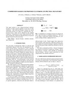
We now discuss the new compression scheme in more detail. As mentioned earlier, it is based on an atypical form of vector clustering which merges groups of deterministic test cubes while allowing some degree of their incompatibility. Consequently, each cluster contains one parent pattern and a number of its derivatives obtained by imposing some extra bits on the parent pattern. Clearly, there is no need to store the entire clusters. Instead, one has to keep only data necessary to recreate (decompress) parent patterns as well as information regarding locations and values of the corresponding incremental bits. These two groups of data will be referred to as control and incremental patterns, respectively. A test controller can then deliver tests by repeatedly applying the same parent pattern, every time using a different incremental pattern. Furthermore, at every scan shift cycle, it uses the associated control pattern to decide whether a given scan chain receives data from the parent pattern, or a current incremental pattern is used instead to recover content of the original test cube it corresponds to. Fig. 1 illustrates principles of the proposed approach. Consider a circuit under test with 111 inputs as shown in the figure. A part of this device is an 8-input multiplexer. In order to detect stuck-at-0 and stuck-at-1 faults on its inputs, one needs to apply test patterns listed in the figure.
Paper 9.2
It is worth noting that these patterns cannot be merged as they all feature mutual conflicts either on data or control lines of the multiplexer. As a result, a conventional compression scheme would need to handle 16 separate test patterns by encoding 16 � (100 + 4) = 1664 specified bits. Since 100 specified bits are identical in all vectors, they can be used to form a parent pattern, while conflicting bits will occur in successive 16 incremental patterns. Their use is determined by a single control pattern driving a multiplexer put in the front of a scan chain. Clearly, the number of specified bits that have to be encoded is now equal to 100 (parent) + 64 (incremental bits) + 111 (control) = 275. As can be easily verified, the reduction ratio with respect to the conventional EDT is roughly 6.05. Recall that the parent pattern and the corresponding control pattern must be applied 16 times for all incremental vectors.
Figure 1.
Compression scheme
The compression algorithm involves three major steps. 1. Given degree � of allowed conflicts, determine the set of parent patterns and all incremental bits associated with every parent pattern. 2. Determine a single control pattern and all incremental patterns for each parent pattern. 3. Encode the parent patterns, the control patterns, and the incremental patterns. This tri-modal encoding process is further described in Section 5. Bits of the parent pattern may assume one of the following four values: 0, 1, x, or C. Clearly, the Boolean values of 0 and 1 represent the specified bits assuming these exact values. x is don’t care, while C is assigned to positions on which at least one conflict has been recorded. A conflict occurs in two cases: (1) two corresponding bits have the opposite specified values, (2) one bit is specified while the other is already labeled as C. The first step of the algorithm is essentially a cube merging process, and it proceeds as follows. Pick a test cube to instantiate a parent pattern P. For every remaining test cube � determine the number of specified bits that this cube has in common with the parent pattern. Also, check P and � to determine if their number of conflicting bits is greater than �. If it is, delete � from the list of cubes that
INTERNATIONAL TEST CONFERENCE
3
could be merged with P. Moreover, check all test cubes that have already been integrated with P to determine the number of conflicting bits they would have with P, if � was a part of P. Again, if at least one of these numbers is greater than �, delete � from the list. Subsequently, scan the entire list of candidate test cubes and pick a few of them with the highest degree of similarity with the current parent pattern (the largest number of common specified bits). Merge the first selected test cube with P and try to encode a newer version of P with Cbits being ignored. If the encoding fails, verify whether P can be compressed with some of newly added specified bits discarded and treated as conflicting bits. This can only be done provided the total number of conflicts does not exceed �. Otherwise, take the next candidate from the short list. The process of forming the parent pattern terminates when none of the short-listed test cubes can be used. If a test cube is successfully added to the parent pattern, all statistics regarding the remaining test cubes are updated and the process continues until no test cubes can be chosen due to incompatibility constrains imposed by factor �. One of the unmerged test cubes becomes now an initial form of a new parent pattern, and the algorithm proceeds as shown above. The process finally terminates when no new parent patterns can be formed. Example. Consider the following parent pattern: P
x 0 x x x x 1 x x x x x x x xCx 1 x x 0 x
This particular parent pattern was obtained after merging the following three test cubes: 1 2 3
x0xxxxxxxxxxxxx1xxxx0x x0xxxx1xxxxxxxx1xxxxxx xxxxxx1xxxxxxxx0x1xx0x
Let the allowed level of conflicts be two. The process of merging considers now other six test cubes as possible candidates for merging. They are listed below. Each test cube is accompanied by its degree of compatibility � (the number of common specified bits with the parent pattern) as well as the number � of conflicts with the parent pattern: 1 2 3 4 5 6
x x x x x x
x 0 1 0 1 1
x x x x x x
x x x x x x
x x x x x x
x x x x x x
0 x 1 1 0 1
x x x x x x
x x x x x x
x x x x x x
x x x x x x
x x x x x x
x x x x x x
x x x x x x
x 1 x x x 1
1 x 0 x x 1
x x x x x x
x 1 x 0 x 1
x x x x x x
x x x x x x
x x x 0 1 0
x x x x 1 x
�
�
0 2 1 3 0 3
2 0 2 1 3 2
The fifth test cube must be rejected as its number of conflicts with the parent pattern (in this particular case 3) is too high. The best candidate seems to be the fourth test cube. It has the same three specified bits as the parent pattern. Also, it features only one conflict. If merged, it would increase the number of conflicts for one of already merged cubes by one, so this is acceptable. It remains to be seen, however, whether the new parent pattern is compressible.
Paper 9.2
If so, the new parent pattern is accepted, statistics for the remaining test cubes are updated, and the process continues. � Once all parent patterns and the incremental bits are known, we can determine the corresponding control data. Let pi and ci denote the i-th bit of the parent pattern and the control pattern, respectively. Bits of the control pattern are then defined as follows: pi = 0 or pi = 1 � ci = 0, pi = C � ci = 1, pi = x � ci = x. The control pattern assumes the value of 0 every time the parent pattern features a specified value. Its value of 1 indicates that the parent pattern has a conflicting bit, and therefore the test data should be provided by the incremental pattern. This pattern, in turn, features the specified bits of 0 and 1 on some of the positions where pi = C. Example. Let the parent pattern be as follows: x x x x x
x x 1 x x
xCx xxx xxx x0x xxx
1 x x x x
x x x x x
x x x x x
xxx 1xx xxx xCx xxx
x x x x x
0 x x x x
x x 0 x x
x x x x x
xxx xxx xxx xxx xCx
x 1 x x x
xCx x xxxx x CC x xxxx xxxx
x x 1 x x
x x x x x
x x x x x
x x x x x
x 0 x x x
x 0 x 1 x
x x x x x
x x x x x
x x x x x
x x x x x
x x x x x
x x x x x
The corresponding control pattern is then of the form: x x x x x
x x 0 x x
x x x x x
1 x x 0 x
x x x x x
0 x x x x
x x x x x
x x x x x
x 0 x x x
x x x 1 x
x x x x x
x x x x x
0 x x x x
x x 0 x x
x x x x x
x x x x x
x x x x 1
x x x x x
x 0 x x x
x x x x x
1 x 1 x x
x x 1 x x
x x x x x
x x 0 x x
x x x x x
x x x x x
x x x x x
x 0 x x x
x 0 x 0 x
One of the incremental patterns may look like the following vector (the specified bits are chosen here arbitrarily just for the sake of illustration; note also that only a subset of C-bits is typically covered by a single incremental pattern as the control pattern serves all incremental patterns associated with a given parent pattern): x x x x x
x x x x x
x x x x x
1 x x x x
x x x x x
x x x x x
x x x x x
x x x x x
x x x x x
x x x 0 x
x x x x x
x x x x x
x x x x x
x x x x x
x x x x x
x x x x x
x x x x 1
x x x x x
x x x x x
x x x x x
0 x x x x
x x x x x
x x x x x
x x x x x
x x x x x
x x x x x
x x x x x
x x x x x
x x x x x
x x x x x
x x x x x
x x x x x
It is worth noting that test application time in the proposed method depends on how many times each parent pattern is applied. This is determined by the number of test cubes that have been merged with a given parent pattern despite conflicts (the compatible test cubes do not require any further action besides just a single application of their parent pattern). Interestingly, compatible incremental vectors of the same parent pattern can be merged in an attempt to further reduce test application time. This can be easily achieved by inspecting successive lists of incremental patterns to determine maximal sets of pair-wise compatible vectors. One has to make sure, however, that the combined incremental patterns can be still encoded by a method adopted to handle these particular vectors.
INTERNATIONAL TEST CONFERENCE
4
4.
Decompressor architecture
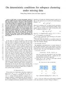
Fig. 2 shows the general structure of a new test data decompressor unit employing the approach presented in Section 3. Essentially, it comprises three modules designated to decompress the parent patterns, the incremental patterns, and the control patterns, respectively. In principle, all decompression techniques adopted here follow the EDT-based continuous flow decompression [40], [41] modus operandi. However, due to particulars characterizing patterns this tri-modal decompressor is to handle, each block is designed in a slightly different way, as described below.
Figure 2.
Decompressor architecture
As can be seen, a 2-input multiplexer is placed in the front of each scan chain. These devices are intended to route decompressed test data from one of two sources: (1) the basic EDT-like decompressor that primarily handles the parent patterns, (2) another decompressor that consists of ring generator 2 with phase shifter 2, which takes care of the incremental patterns. The actual source is determined by applying appropriate select signals to the multiplexers. These signals are provided by the third decompression logic employed here to handle the control patterns. Ring generator 1 and phase shifter 1 constitute the first part of our new decompression logic. This is virtually a sequential continuous flow decompressor whose logic synthesis and corresponding compression algorithms have already been presented elsewhere [37], [39], [41]. As men-
Paper 9.2
tioned earlier, this part of decompressor is deployed to decode the parent patterns which are subsequently fed to the scan chains unless the control signals decide otherwise. As demonstrated in Section 3, the control patterns feature a relatively large number of zeros (corresponding to the specified bits of the parent patterns) with the sparse presence of ones (corresponding to C-bits). To encode such patterns it suffices to target only a small subset of 0bits as long as they occur in sequences no interspersed with 1-bits. For example, a sequence xxx0xxxx0xx0xxxxx0x1xx0xxxx0xx • • •
can be efficiently encoded by taking into account only indicated bits, and by assuming that the decompressor outputs are sustained for more than a single clock cycle to deliver the identical test data (here to the multiplexer select inputs) for a number of shift cycles. With such a mechanism, the number of specified bits that need to be encoded is drastically reduced. The same rule applies to 1-bits, though their continuous appearance in control patterns is less frequent. In order to implement the above idea, we use a shadow register to keep the decompressor outputs unchanged. It is placed between ring generator 1 and phase shifter 3. The shadow register captures and saves, for a number of cycles, a desired state of ring generator 1, while the generator itself keeps advancing to the next states in order to encode upcoming specified bits. Note that we reuse ring generator 1 as its encoding capabilities are sufficient to handle very low control pattern fill rates. Interestingly, the decompressor input channels also facilitate the operation of the shadow register by using seed variables to deliver a load enable signal, as shown in Fig. 2. Small buffers placed in parallel with the decompressor inputs drive an XOR tree which computes a parity of input variables, including not only data currently entering the ring generator, but also those used in previous cycles. If this signal is 1, then the shadow register is reloaded with the current content of ring generator 1 before new seed variables enter the generator (and it reaches its next state). Otherwise, the content of the register remains unchanged. The third part of the decompressor is used to decode the incremental patterns. It consists of ring generator 2 and phase shifter 2. As the incremental test patterns feature extremely sparse specified bits (corresponding to C-bits), they do not require all variables, which would be injected within the conventional framework of EDT scheme. Hence, injections of new test data occur regularly in rare and predetermined scan shift cycles only. Such an approach further elevates the compression ratio and adheres conveniently to the ATE ability of repeating the same patterns multiple times. Alternatively, every set of new variables can be injected once, and then buffered, for a requested number of cycles, as shown at the top of Fig. 2. A decompressor comprising three separate modules has also been proposed in [51]. This scheme combines a 3weight pseudorandom testing with LFSR reseeding. It em-
INTERNATIONAL TEST CONFERENCE
5
ploys a pseudo-random test pattern generator to feed scan chains and handle conflicts. Moreover, if certain test cubes feature the same specified bits, then such bits are provided by additional two LFSRs that produce a value and indicate a scan shift cycle when this value should replace data arriving from the PRPG. Both LFSRs have a reseeding ability and are controlled by an external tester. In order to reduce the ATE channels bandwidth, compressed parent patterns can be delivered to a circuit under test only once, and then stored on chip by deploying either a small memory or certain scan chains acting as circular buffers. The second approach takes advantage of low fill rates allowing several scan chains to be specified bits-free, and, moreover, not affected by fault propagation sites. Indeed, many experimental evidences indicate that a small number of scan chains suffice to accommodate all compressed parent and control patterns. Once the parent pattern is stored, the bandwidth requirements scale down as the incremental patterns need only a fraction of the original tester interface throughput. Possible underutilization of external channels opens new research directions that one may explore in order to further enhance the overall efficiency of deterministic test data compression.
5.
Encoding algorithm
The decompressor architecture is tightly coupled with the encoding algorithm, where all specified bits are represented by linear functions of variables injected into the decompressor. A compressed pattern is then determined by solving the system of linear equations in the Galois field modulo 2. In particular, this technique applies to the parent patterns, whose corresponding equations are formed based on a feedback polynomial implemented by ring generator 1 and structure of phase shifter 1. Recall that C-bits occurring in the parent patterns are not the subject of encoding. Good as it is, the continuous flow compression is less efficient at encoding control and incremental patterns because a way linear equations are created keeps the method from capturing the more subtle relationships between specified bits in these two types of vectors. More effective are two schemes presented in the following, which build on repetitive sequences and a rare occurrence of certain specified values. As mentioned earlier, we employ a shadow register to address a crucial feature the control patterns exhibit: 0-bits are predominant specified values while 1-bits occur sparsely. This property is a key factor in reducing the volume of test data as one may deliver the identical data to the multiplexers for a number of scan shift cycles. Consequently, the encoding algorithm partitions a given control pattern into several blocks comprising certain number of consecutive slices such that there are no scan chains with both 0’s and 1’s inside the same block. This allows one to repeat a given combination many times in succession by using the shadow register storing a state that the ring generator entered at the beginning of a block. Such a technique gives the ring generator enough time to compensate for fading encoding ability by collecting new input vari-
Paper 9.2
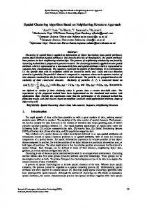
ables. They will facilitate successful compression during next steps once the shadow register is reloaded. The ability of a decompressor to decode data within boundaries of the block determines its size. Hence, the following four rules govern the encoding process: • it begins with a block and the corresponding state of a ring generator which should be applied first, and it gradually moves towards the end of a control pattern, • whenever specified bits of the same value are repeated many times in succession (possibly interspersed with don’t care bits) within the same block and the same scan chain, there is no need to encode all of them but the first one, • for each scan shift cycle there is an associated equation representing a request to store, if needed, the content of the ring generator in the shadow register before new variables change the state of the generator during the next cycle, • an equation representing the first specified bit in the current block and in a given scan chain is expressed in terms of variables injected until this block. The last rule is needed as a ring generator state which is to cover a given bit has to be completely determined before it is moved to the shadow register during the first cycle of a next block. This is equivalent to conceptually moving this specified bit to the beginning of the block. As long as such bits can be encoded, the algorithm works by repeatedly increasing the size of the block, and by adding new equations, if necessary. At some point a solution may not exist anymore. This particular time frame is then assigned a new block, and the procedure continues. Example. Consider a 2-input decompressor employing a shadow register controlled by 4-input XOR gate whose inputs comprise the last two variables injected through each input of the ring generator (Fig. 2). Suppose we need to encode a control pattern shown in Fig. 3a (white dots denote 0’s while black dots correspond to 1-bits; bits to be considered first are located on the right). The input variables a0, b0, a1, b1 ..., are provided in pairs. Fig. 3b illustrates a hypothetical partition of the control pattern into blocks with those specified bits that need to be encoded highlighted. By relocating these specified bits to the border lines of the blocks, we get locations corresponding to linear equations that will be used to perform actual encoding (Fig. 3c). Note that a new block is formed (with the shadow register reloaded) anytime a given scan frame has a conflict with the previous slice. Furthermore, one has to remember that a set of linear equations used by the compression procedure must include one additional equation per every scan slice (time frame) of the following form: ak + bk + ak–1 + bk–1 = r, where r is equal to 1, if the shadow register is to be reloaded during the k-th scan shift cycle, and it assumes the value of 0, otherwise. In general, the number of variables used in the above equation depends on the number of decompressor external channels and the size of input buffers, as shown in Fig. 2. �
INTERNATIONAL TEST CONFERENCE
6
two tester channels drive a decompressor. Consider the following equation: a0 + b0 + a1 + a2 + b3 = 1. If the algorithm is to replace variables injected during the second and fourth steps (i.e., a1, b1, a3, and b3) with variables injected during the first and third cycles (i.e., a0, b0, a2, and b2), then we clearly have: a0 + b0 + a0 + a2 + b2 = b0 + a2 + b2 = 1. To accomplish this action in a time-efficient manner, we use an array of bits to represent variables. The part of each equation corresponding to omitted variables is then added modulo 2, in a bit-wise fashion, to the replacement part. If we continue this way until all variables are examined, the resulting equation will have exactly the same form as the one obtained by symbolic simulation of the decompressor with certain variables repeatedly injected several times. The eliminated variables are eventually replaced with 0s.
6.
Figure 3.
Compression of control patterns
Contrary to the parent and control patterns, the incremental patterns feature very low fill rates. Their compression, therefore, is possible even if only a small subset of variables is employed. In this paper, the under-sampling rate, i.e., the number of injections repeating the same variables, is chosen as an integer ratio of the maximal number of variables that might be injected and the number of specified bits. It should be noted that as long as the solver cannot compress an incremental pattern, the whole algorithm repeatedly decreases this rate (until it reaches the value of 1), creates a new set of equations, and invokes the solver again. The concept of using the subset of variables is paired with an efficient technique to form linear equations for successive incremental patterns and possibly different values of the under-sampling rate if the solver fails to compress the incremental pattern in the first place. All equations are created initially by assuming that variables are injected every clock cycle. This step needs only be done once. Subsequently, equations corresponding to a particular incremental pattern are further modified as follows. If certain variables are not used, they are replaced with variables injected in the previous scan shift cycle. Suppose
Paper 9.2
Experimental results
The proposed compression scheme was tested on several industrial designs. This section reports results for some of them, ranging in size from 220K to 2.2M gates. The basic data regarding the designs: the number of gates and number of scan cells are listed in the left part of Table II. All reported experiments were performed for both stuck-at tests and launch-off-capture transition tests. Consequently, the next two entries to the table report the resultant number of test patterns and the total number of specified bits these patterns feature. Finally, for the sake of reference, the best results obtained for the conventional EDT-based compression scheme are reported in the last two columns. They include the amount of compressed test data and the resultant test data volume compression. TABLE II. CIRCUIT CHARACTERISTICS Design
Gates
Scan cells
Test patterns
Specified bits
EDT test data
D1 D2 D3 D4 D5 D6
220K 545K 1.3M 1.1M 260K 2.2M
13K 45K 86K 70K 14K 144K
1,573 3,223 4,214 10,466 37,050 24,137
171,192 1,408,878 1,728,581 5,127,107 6,084,081 1,833,154
201,344 2,301,222 2,098,572 19,048,120 10,448,100 26,792,070
EDT com press 98 63 174 39 50 129
The results of the experiments are summarized in Table III. The first part of the table consists of three columns, each entry of which specifies the scan configuration and the decompressor architecture. Note that columns “Ring 1” and “Ring 2” are used to designate the size of ring generator 1 and ring generator 2, respectively. Information regarding the number of inputs, i.e., the number of decompressor channels connecting ATE with both ring generators, as shown in Fig. 2, is given in the same columns. The remaining parts of Table III list various performance-related statistics of the proposed compression
INTERNATIONAL TEST CONFERENCE
7
scheme. In particular, for each test case the following information is provided: • the maximal number of allowed conflicts when merging original test cubes, • the number of parent and incremental patterns (recall that the number of control patterns is the same as that of the parent patterns), • the total number of bits that have to be encoded; this quantity includes the total number of specified bits occurring in the parent patterns, the total number of incremental bits as well as the total number of control bits – the latter value is equal to the number of parent specified bits plus the number of all incremental bit sites as seen by a given parent pattern (compare a detailed breakdown of such data presented in Table I), • the total number of bits encoding parent, and control patterns, and, separately, incremental patterns, • the total test data volume used to encode all specified bits listed above, • the encoding efficiency of the tri-modal scheme, i.e., the ratio of the total number of specified bits as presented (for each design) in Table I and the number of bits (test data) reported in the previous column, • the effective test data volume compression resulting from using our scheme; this quantity is obtained as a ratio of the following two values: the number of scan cells multiplied by the number of test patterns and the amount of test data reported in column “Total test data” of Table III. As indicated by data in the last column of Table III, application of our scheme produces remarkable compression levels. In all examined test cases, the proposed solu-
tion yields significantly higher compression than that of the conventional EDT-based scheme. The observed increase in test data compression varies from 3.5 to almost 36 times (or well above 4,500x in absolute numbers). Note that the test coverage stays unaffected in each case while keeping the required added test logic on the circuit under test to a minimum. In particular, it appears that a single scan channel suffices in all test cases to operate the decompressor designated to handle incremental patterns. The proposed approach compares favorably to earlier test data reduction schemes as far as compression and encoding efficiency are concerned. For instance, the “restrict encoding” scheme of [12] is capable of delivering 1.58 coding efficiency on the average with the corresponding maximum value reaching level of 2.0. As shown in Table III, the average encoding efficiency computed across industrial designs examined in this work is equal to 4.08 with the maximal efficiency elevated to the value of 7.93. Clearly, these numbers are much higher than those of conventional static and dynamic reseeding-based compression schemes. In fact, to the best of our knowledge, this is the first test data volume compression scheme achieving such extreme encoding efficiency. Deterministic encoding, moreover, allows the proposed method to handle any number of conflicts (provided it does not compromise compression), as opposed to simply applying pseudo-random patterns to conflicting bits as done in [26] at the cost of significantly increased test application time. For each design, there exists a “sweet spot” where a combination of several factors, including primarily the number of allowed conflicting bits, the resultant number of parent patterns, incremental bits as well as their locations,
TABLE III. EXPERIMENTAL RESULTS Design
D1
D2
D3
D4
D5
D6
Scan chains (no � size)
Ring 1 inputs
Ring 2 inputs
122 � 104 122 � 104 122 � 104 128 � 353 128 � 353 128 � 353 80 � 1081 80 � 1081 122 � 709 80 � 878 80 � 878 160 � 439 120 � 119 120 � 119 120 � 119 244 � 588 160 � 897 244 � 588
64 – 6 64 – 5 64 – 6 64 – 5 64 – 6 32 – 5 64 – 3 64 – 4 64 – 3 64 – 6 64 – 6 64 – 6 32 – 4 64 – 3 32 – 5 64 – 3 32 – 3 64 – 4
16 – 1 16 – 1 16 – 1 16 – 1 16 – 1 16 – 1 24 – 1 24 – 1 16 – 1 16 – 1 16 – 1 16 – 1 16 – 1 16 – 1 16 – 1 16 – 1 16 – 1 16 – 1
Paper 9.2
Allowed Parent con- patterns flicts 20 16 16 32 32 28 32 28 32 32 28 20 32 32 32 28 28 28
23 36 31 84 76 109 73 59 106 70 78 181 972 1001 935 169 126 130
Incremental patterns
Total bits to encode
Test data for parent & control
Test data for incremental
Total test data
Encoding efficiency
Comp. over EDT
Compression [x]
1,963 1,892 1,806 6,938 6,361 7,214 5,209 3,983 6,340 8,810 8,758 9,758 36,287 36,915 36,361 25,520 24,816 25,955
92,142 83,545 82,868 662,795 662,241 632,334 852,653 809,614 850,737 864,905 853,431 853,215 1,649,092 1,639,904 1,649,134 906,585 905,973 887,617
15,870 21,060 21,390 153,720 165,984 196,200 241,557 258,892 232,458 373,380 416,052 488,700 493,776 423,423 589,050 309,270 343,224 314,080
37,147 32,879 33,354 196,528 184,517 163,639 241,163 228,231 255,087 275,743 253,129 197,141 1,163,947 886,269 1,171,064 448,434 425,467 455,232
53,017 53,939 54,744 350,248 350,501 359,839 482,720 487,123 487,545 649,123 669,181 685,841 1,657,723 1,735,230 1,760,114 757,704 768,691 769,312
3.40 3.34 3.29 4.12 4.11 4.01 3.59 3.56 3.56 7.93 7.69 7.51 3.71 3.54 3.49 2.43 2.40 2.39
3.79 3.73 3.67 6.57 6.56 6.39 4.34 4.30 4.30 29.34 28.46 27.77 6.30 6.02 5.93 35.35 34.85 34.82
373 367 362 416 415 405 754 748 747 1,132 1,098 1,071 317 303 299 4,570 4,505 4,501
INTERNATIONAL TEST CONFERENCE
8
leads to a particularly suitable solution in terms of encoding efficiency and compression levels. Indeed, as one may expect, with the increasing number of conflicts, the number of parent patterns decreases. This trend is clearly counterbalanced by the increase in incremental bits (and then patterns). Both quantities (plus the corresponding control patterns) must eventually be encoded by using certain amounts of test data in each case. Their sum can be regarded as a cost function. By proper selection of the maximal number of conflicting bits, the decompressor size (mainly ring generator 1), and the number of scan channels, one can search for optimal sets of test data such that the cost function is minimized, or alternatively the compression is maximized. It is worth noting that information listed in column “Incremental patterns” essentially estimates test application time. Recall that initial incremental patterns obtained in parallel with the process of forming successive parent patterns can be further merged provided they are mutually compatible. Eventually, tests are delivered by repeatedly applying successive parent patterns, every time using a next incremental pattern, i.e., a derivative of the current parent. The incremental pattern count is therefore indicative of the expected test time. Interestingly, test application time in the case of designs D3, D4, D5, and D6 is either virtually the same as that of the conventional EDT or even shorter (see the number of test patterns in Table II).
7.
Conclusion
One of the key requirements for the future compression scheme is to further and significantly reduce the amount of test data. With the size of test patterns growing at alarming rates, the new approach presented in this paper provides a coherent way to generate and apply extremely compressed test patterns in a cost effective manner, for any fault model used today and for any fault model or defect-based testing scenario of the future. Similarly to the EDT scheme, the proposed scheme is non-intrusive as it requires no modifications to the core logic, such as test points or X-bounding logic. And still, it offers a substantial increase in coding efficiency. Moreover, it integrates seamlessly with a test logic synthesis flow and fits into the core-based design paradigm, where only a few external pins can be employed to drive a large number of internal scan chains in the cores. Finally, as this new compression preserves all benefits of continuous flow decompression, it provides a smooth migration path to the next-generation test data compression solutions while maintaining very high quality of test and minimizing design and manufacturing cost impacts.
8.
Acknowledgment
The work of D. Czysz and J. Tyszer was supported in part by the SRC under Grant 2007-TJ-1584.
9.
References
[1] C. Barnhart, et al., “Extending OPMISR beyond 10x scan test efficiency,” IEEE Design and Test of Computers, vol. 19, No. 5, pp. 65-73, 2002.
Paper 9.2
[2] K.J. Balakrishnan and N.A. Touba, “Relating entropy theory to test data compression,” Proc. ETS, pp. 187-192, 2004. [3] K.J. Balakrishnan and N.A. Touba, “Improving linear test data compression,” IEEE Trans. VLSI, vol. 14, pp. 12271237, Nov. 2006. [4] I. Bayraktaroglu and A. Orailoglu, “Test volume and application time reduction through scan chain concealment,” Proc. DAC, pp. 151-155, 2001. [5] I. Bayraktaroglu and A. Orailoglu, “Concurrent application of compaction and compression for test time and data volume reduction in scan designs,” IEEE Trans. Comput, vol. 52, pp. 1480-1489, Nov. 2003. [6] A. Chandra and K. Chakrabarty, “Test data compression and test resource partitioning for system-on-a-chip using frequency-directed run-length (FDR) codes,” IEEE Trans. Comput., vol. 52, pp. 1076-1088, Aug. 2003. [7] A. Chandra and K. Chakrabarty, “System-on-a-chip testdata compression and decompression architectures based on Golomb codes,” IEEE Trans. CAD, vol. 20, pp. 355-368, Mar. 2001. [8] D. Das and N.A. Touba, “Reducing test data volume using external/LBIST hybrid test patterns,” Proc. ITC, pp. 115122, 2000. [9] R. Dorsch and H.-J. Wunderlich, “Tailoring ATPG for embedded testing,” Proc. ITC, pp. 530-537, 2001. [10] V. Gherman, et al., “Efficient pattern mapping for deterministic logic BIST,” Proc. ITC, pp. 48–56, 2004. [11] P.T. Gonciari, B.M. Al-Hashimi, and N. Nicolici, “Variable length input Huffman coding for system-on-a-chip test,” IEEE Trans. CAD, vol. 22, pp. 783-796, June 2003. [12] A.-W. Hakmi, et al., “Programmable deterministic built-in self-test,” Proc. ITC, paper 18.1, 2007. [13] A.-W. Hakmi, et al., “Restrict encoding for mixed-mode BIST,” Proc. VTS, 2009, to appear. [14] I. Hamzaoglu and J. Patel, “Reducing test application time for built-in self-test pattern generators,” Proc. VTS, pp. 369376, 2000. [15] I. Hamzaoglu and J. Patel, “Reducing test application time for full scan embedded cores,” Proc. Int. Symp. On Fault Tolerant Computing, pp. 260-267, 1999. [16] K. Hatayama, M. Nakao, Y. Kiyoshige, and K. Natsume, “Application of high-quality built-in test to industrial designs,” Proc. ITC, pp. 1003-1012, 2002. [17] S. Hellebrand, et al., “Built-in test for circuits with scan based on reseeding of multiple-polynomial linear feedback shift registers,” IEEE Trans. on Comput., vol. 44, pp. 223233, Feb. 1995. [18] S. Hellebrand, H.-G. Liang, and H.-J. Wunderlich, “A mixed mode BIST scheme based on reseeding of folding counters,” Proc. ITC, pp. 778-784, 2000. [19] F. Hsu, K. Butler, and J. Patel, “A case study on the implementation of the Illinois scan architecture,” Proc. ITC, pp. 538-547, 2001. [20] H. Ichihara, A. Ogawa, T. Inoue, and A. Tamura, “Dynamic test compression using statistical coding,” Proc. ATS, pp. 143-148, 2001. [21] H. Ichihara, K. Kinoshita, I. Pomeranz, and S.M. Reddy, “Test transformation to improve compaction by statistical encoding,” Proc. Int. Conf. on VLSI Design, pp. 294-299, 2000. [22] A. Jas, J. Ghosh-Dastidar, and N.A. Touba, “Scan vector compression/decompression using statistical coding,” Proc. VTS, pp. 114-120, 1999.
INTERNATIONAL TEST CONFERENCE
9
[23] A. Jas and N.A. Touba, “Test vector decompression via cyclical scan chains and its application to testing core-based designs,” Proc. ITC, pp. 458-464, 1998. [24] B. Keller, et al., “OPMISR: The foundation for compressed ATPG vectors,” Proc. ITC, pp. 748-757, 2001. [25] B. Koenemann, “LFSR-coded test patterns for scan designs,” Proc. European Test Conference, pp. 237-242, 1991. [26] B. Koenemann, “Care bit density and test cube clusters: multi-level compression opportunities,” Proc. ICCD, pp. 320-325, 2003. [27] B. Koenemann, et al., “A SmartBIST variant with guaranteed encoding,” Proc. ATS, pp. 325-330, 2001. [28] C. Krishna, A. Jas, and N.A. Touba, “Test vector encoding using partial LFSR reseeding,” Proc. ITC, pp. 885-893, 2001. [29] C.V. Krishna and N.A. Touba, “Reducing test data volume using LFSR reseeding with seed compression,” Proc. ITC, pp. 321-330, 2002. [30] C.V. Krishna and N.A. Touba, “Adjustable width linear combinational scan vector decompression,” Proc. ICCAD, pp. 863-866, 2003. [31] C.V. Krishna and N.A. Touba, “3-stage variable length continuous-flow scan vector decompression scheme,” Proc. VTS, pp. 79-86, 2004. [32] K-J. Lee, J-J. Chen, and C-H. Huang, “Using a single input to support multiple scan chains,” Proc. ICCAD, pp. 74-78, 1998. [33] J. Lee, and N.A. Touba, “Combining linear and non-linear test vector compression using correlation-based rectangular coding,” Proc. VTS, pp. 252-257, 2006. [34] L. Li, K. Chakrabarty, and N.A. Touba, “Test data compression using dictionaries with selective entries and fixedlength indices,” ACM Trans. Design Automation of Electronic Systems, vol. 8, no. 4, pp. 470-490, Oct. 2003. [35] H-G. Liang, S. Hellebrand, and H.-J. Wunderlich, “Twodimensional test data compression for scan-based deterministic BIST,” Proc. ITC, pp. 894-902, 2001. [36] S. Mitra and K.S. Kim, “XPAND: An efficient test stimulus compression technique,” IEEE Trans. Comput., vol. 55, pp. 163-173, Feb. 2006. [37] G. Mrugalski, J. Rajski, and J. Tyszer, “Ring generators new devices for embedded test applications,” IEEE Trans. CAD, vol. 23, pp. 1306-1320, Sept. 2004. [38] I. Polian, A. Czutro, and B. Becker, “Evolutionary optimization in code-based test compression,” Proc. DATE, pp. 1124-1129, 2005. [39] J. Rajski, N. Tamarapalli, and J. Tyszer, “Automated synthesis of phase shifters for built-in self-test applications,” IEEE Trans. CAD, vol. 19, pp. 1175-1188, Oct. 2000. [40] J. Rajski, et al., “Embedded deterministic test for low cost manufacturing test,” Proc. ITC, pp. 301-310, 2002. [41] J. Rajski, J. Tyszer, M. Kassab, and N. Mukherjee, “Embedded deterministic test”, IEEE Trans. CAD, vol. 23, pp. 776792, May 2004.
Paper 9.2
[42] J. Rajski, J. Tyszer, and N. Zacharia, “Test data decompression for multiple scan designs with boundary scan,” IEEE Trans. Comput., vol. 47, pp. 1188-1200, Nov. 1998. [43] W. Rao, I. Bayraktaroglu, and A. Orailoglu, “Test application time and volume compression through seed overlapping,” Proc. DAC, pp. 732-737, 2003. [44] S.M. Reddy. K. Miyase, S. Kalihara, and I. Pomeranz, “On test data volume reduction for multiple scan chain design,” Proc. VTS, pp. 103-108, 2002. [45] X. Sun, L. Kinney, and B. Vinnakota, “Combining dictionary coding and LFSR reseeding for test data compression,” Proc. DAC, pp. 944-947, 2004. [46] H. Tang, S.M. Reddy, and I. Pomeranz, “On reducing test data volume and test application time for multiple scan designs,” Proc. ITC, pp. 1079-1088, 2003. [47] M. Tehranipoor, M. Nourani, and K. Chakrabarty, “Ninecoded compression technique for testing embedded cores in SoCs,” IEEE Trans. VLSI, vol. 13, June 2005, pp. 719-731. [48] N.A. Touba, “Survey of test vector compression techniques,” IEEE Design & Test of Computers, vol. 23, pp. 294-303, July-Aug. 2006. [49] N.A. Touba and E.J. McCluskey, “Altering a pseudorandom bit sequence for scan-based BIST,” Proc. ITC, pp. 167-175, 1996. [50] K.-H. Tsai, J. Rajski, M. Marek-Sadowska, “Star test: the theory and its applications,” IEEE Trans. CAD, vol. 19, pp. 1052-1064, Sept. 2000. [51] S. Wang, K.J. Balakrishnan, and S.T. Chakradhar, “XWRC: Externally-loaded weighted random pattern testing for input test data compression,” Proc. ITC, paper 24.2, 2005. [52] Z. Wang and K. Chakrabarty, “Test data compression for IP embedded cores using selective encoding of scan slices,” Proc. ITC, pp. 581-590, 2005. [53] P. Wohl, J.A. Waicukauski, S. Patel, and M.B. Amin, “Efficient compression and application of deterministic patterns in a logic BIST architecture,” Proc. DAC, pp. 566-569, 2003. [54] P. Wohl, J.A. et al., “Efficient compression of deterministic patterns into multiple PRPG seeds,” Proc. ITC, pp. 916-925, 2005. [55] H.-J. Wunderlich and G. Kiefer, “Bit-flipping BIST,” Proc. ICCAD, pp. 337-343, 1996. [56] A. Würtenberger, C.S. Tautermann, and S. Hellebrand, “Data compression for multiple scan chains using dictionaries with corrections,” Proc. ITC, pp. 926-935, 2004. [57] E.H. Volkerink, A. Khoche, and S. Mitra, “Packet-based input test data compression techniques,” Proc. ITC, pp. 154163, 2002. [58] E.H. Volkerink and S Mitra, “Efficient seed utilization for reseeding based compression,” Proc. VTS, pp. 232-237, 2003. [59] A.A. Al-Yamani, S. Mitra, and E.J. McCluskey, “BIST reseeding with very few seeds,” Proc. VTS, pp. 69-76, 2003.
INTERNATIONAL TEST CONFERENCE
10