Proceedings of EPAC 2002, Paris, France
COMPUTATION OF RF-PROPERTIES OF LONG AND COMPLEX STRUCTURES* D. Hecht†, K. Rothemund, H.-W. Glock‡, U. van Rienen, Universität Rostock, Institut für Allgemeine Elektrotechnik, D – 18051 Rostock, Germany Abstract Numerical calculation of RF-properties of accelerating structures is typically performed by numerical field solving codes such as MAFIA [1] or Microwave Studio™ [1]. Even if components like cavities are of cylindrical symmetry, full 3D modelling is required in order to consider the effects of power- or HOM-couplers. This implies a numerical effort significantly higher than the separate treatment of parts with and without rotational symmetry. Therefore we have developed a method called Coupled S-Parameter Calculation (CSC) which is based on a scattering parameter description. It uses Sparameters of the various components and results in the entire structure’s scattering properties. The S-parameters of the single components are computed by customary field solving codes utilizing any component’s symmetry or repetition of subsections. The authors want to demonstrate the capabilities of CSC reporting results on the effect of different HOM-coupler geometries in the TESLA channel and compare the effects of different cavity- and coupler arrangements. From the CSC data the frequencies and the Q-factors of the modes in TESLA cavities are calculated.
1 INTRODUCTION The TESLA project is a study for a high energy e+-elinear collider [2] which foresees superconducting accelerating structures with a driving frequency of 1.3 GHz. Even though the wake field problem is rather relaxed with this machine compared to the corresponding X-band projects, nevertheless it has to be studied carefully. Measurements took place in the TESLA Test Facility (TTF) where Higher Order Modes (HOMs) have been found in some of the accelerating structures which were not sufficiently damped by the Higher Order Mode couplers. Several experimental and numerical studies have been carried out by different research groups in order to understand the underlying phenomenon [3]. In this paper we report about our studies concerning variations of the geometry of the HOM couplers, as proposed recently, to estimate their effects on the not sufficiently damped higher order modes. As this system is too complex to be computed as a whole in reasonable time on a workstation, the Coupled S-Parameter Calculation method [4] was applied. * This work was supported in part by DESY, Hamburg †
[email protected] ‡ on sabbatical leave from the Institut für Allgemeine Elektrotechnik, Universität Rostock, D – 18051 Rostock, Germany permanent e-mail address:
[email protected]
2 COUPLED S-PARAMETER CALCULATION The numerical analysis of radio frequency (rf) components usually is based on the discretization of Maxwell’s equations with grids covering the entire structure. The CSC algorithm is a tool developed in order to split the calculation of structures being too large for the available computing power. It is based on the partitioning of the entire structure in several sections and on the expansion of the electromagnetic field in waveguide eigenmodes at the cutting planes. The individual section’s rf properties are expressed in terms of waveguide mode scattering: reflection and transmission coefficients (normally frequency dependent) are collected in a matrix S, the so-called scattering matrix (see e.g. [5]). Numerically the scattering properties are calculated by exciting a broadband signal at one port, computing the time development of the field distribution in the section and keeping track of the signals leaving it at all ports; this provides one column of the S-matrix. For some simple structures like waveguides with rectangular or circular cross section the S-matrix can be determined analytically. The S-matrix formalism allows to calculate the scattering properties of the entire structure using those of the individual sections. Especially it eases the exploitation of symmetries and repetitions of certain subsections in the structure. CSC provides a means to derive the scattering properties of complex structures with no restrictions of the structures topology, port numbers and mode numbers. In the case of a resonator (no open ports) CSC determines the resonant frequencies and provides the excitation coefficients at all cutting planes of the complete structure to compute the field distribution of the eigenmodes. This can either be done by time domain or by frequency domain solvers exciting waveguide modes of the appropriate frequency and (complex) amplitude simultaneously at all cutting planes. A detailed description of the CSC theory can be found in [4] and [6] .
3 Q-VALUE DETERMINATION FROM SPARAMETERS Many rf devices have a resonant behaviour. Then a set of resonance frequencies and Q values are the main quantities used to characterize the object. Therefore we developed a procedure to extract these quantities from previously calculated S(f) curves. These S-parameter curves are assumed to follow the (complex) relation
1685
Proceedings of EPAC 2002, Paris, France N
S( f ) = ∑
ak k =1 2πif − p k
(1)
with f the frequency, N the number of poles, ak and pk the coefficients, describing the pole. Then the resonance frequency fk of the k-th resonance is given by Im(pk)/2π and its Q-value results to –Im(pk)/2 Re(pk). So both parameters are known, if pk is determined from the Sparameter curve. The method shown here is based on the assumption that all other contributions can be summarized in a frequency-independent residual Rk in the vicinity of one resonance frequency. Thus the relation
S( f ) =
ak + Rk 2πif − pk
(2)
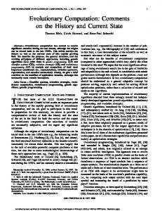
beam pipe is shortened at both ends of the cavity at a distance of L2,u = 101.4 mm and L2,d = 65.4 mm (measured from the middle plane of the HOM-coupler). In one set-up the power-coupler was left empty and the port was closed; in another variant it was equipped with the inset but the coaxial port was shortened. The coaxial ports of both HOM-couplers were left open. To compare the effects of geometry variations the following set-ups were computed: • input coupler empty and closed, HOM-coupler original orientation • input coupler empty and closed, HOM-coupler mirrored – a set-up suggested by M. Dohlus [8] • input coupler with inner conductor (shortened), HOM-coupler original orientation
holds in the vicinity of a certain pole k. Furthermore Sj (fj) has to be known for a sufficient number z of different fj in the frequency range near the pole. This leads to an overdetermined set of equations of the form 2π i fj Rk + Sj(fj) pk – (pkRk – ak) = 2π i fj Sj(fj) which may be written in matrix-vector notation as
r r M x=v,
with
2πi S1 f1 r v = M 2πi S f z z
2π f 1 M = M 2π f z r and x = p k
S 1 −1 M M , S z −1 Rk pk . Rk − ak
In the sense of minimal least square this system has the explicit solution
Figure 1: Geometry set-up for CSC calculation. The scattering parameters of the TESLA-cavity were calculated from modal coefficients [8]. The S-parameters of shorts and beam pipes were calculated analytically and the HOM-coupler and HOM-input-coupler sections were modelled in MicrowaveStudio™.
−1 r r x = ( M M ) M + v with M the
adjoint matrix of M which directly yields the parameters searched for, i.e. pk , ak and Rk - the latter serving as a reliability check. The success of this procedure strongly depends on the selection of frequency points used for the overdetermined system. Taking a span of a few dB on one side of a resonance curve, starting from the maximum, usually gives good results. In special cases like the spectrum shown in figure 3 with resonances of strongly varying Q-values, an additional step needs to be performed by the user: Then, in a first run it is necessary to subtract the contribution of the lowQ-resonances found from the S-parameter curve, afterwards repeating the procedure with the remaining signal. The procedure was implemented like CSC using Mathematica™ [7]. Its computing effort is negligible.
4 GEOMETRY SET-UP We present calculations of S-parameter and resonances of an arrangement chosen similar to a test stand set-up used for measurements at DESY: the TESLA-9-cellcavity is equipped upstream with a HOM coupler and downstream with a HOM-input-coupler combination. The
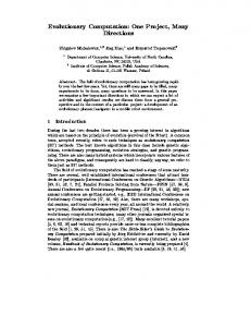
Figure 2: HOM-coupler in original (left) and mirrored (right) variant. The input-coupler port has no inner conductor and is closed. The figure shows the geometry modelled by MicrowaveStudio™ used for the calculation.
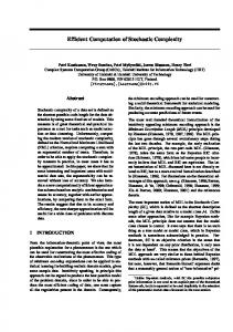
5 COMPUTATIONAL RESULTS For all three set-ups CSC yields transmission coefficients HOM1-HOM2 in the range of the second dipole pass band (2.47 GHz – 2.58 GHz), showing eight high-Q resonances accompanying eight well known lowQ resonances. The Q-values of the high-Q resonances are strongly depending on the HOM coupler orientation and on the presence of the inner conductor in the input coupler. A very narrow frequency sampling is needed in the vicinity of the high Q resonances. This can be provided by interpolating the component’s S-parameters which usually are of weak frequency dependence.
1686
Proceedings of EPAC 2002, Paris, France
were found with the same frequencies (6 valid digits) as found from the pole extraction method.
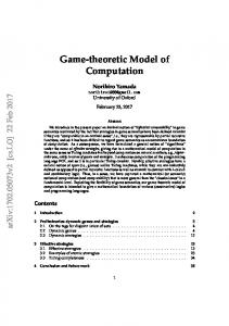
6 CONCLUSIONS The CSC method significantly reduces the effort to compute rf properties of complex structures. The scattering properties resulting from its application can be interpreted using a pole identification method to derive resonant frequencies and Q values. Under appropriate circumstances HOM-resonances with extremely high Q values (> 106) can be indicated in the TESLA cavity with HOM couplers, even though they are sensitive against variations of coupler geometries.
Figure 3: CSC-calculated |S21| of set-up a) (grey dots) and some of the poles according eq. (1) (black line). Full spectrum (above, missing of narrow peaks due to plot sampling) and detail of high-Q and low-Q-resonance.
Figure 4: Spectra of Q-values extracted from CSCcalculated |S21| for three different set-ups
7 ACKNOWLEDGEMENT The authors wish to thank M. Dohlus, DESY, for many fruitful discussions and his steady support.
8 REFERENCES [1] CST GmbH, Büdinger Str. 2a, D-64289 Darmstadt, Germany [2] R. Brinkmann et al.: TESLA – The Superconducting Electron-Positron Linear Collider with an Integrated X-Ray Laser Laboratory -Technical Design Report, DESY 2001-011, Hamburg, March 2001 [3] N. Baboi, M. Dohlus, C. Magne, A. Mosnier, O. Napoly, H.-W. Glock: Investigation of a High-Q Dipole Mode at the TESLA Cavities, Proceedings of the 7th European Particle Accelerator Conference (EPAC 2000),Vienna [4] K. Rothemund, H.-W. Glock, U. van Rienen: Calculation of Electromagnetic Eigenmodes in Complex Structures Using Coupled S-Parameter Calculation, in: U. van Rienen, M. Günther, D. Hecht (eds.), Scientific Computing in Electrical Engineering, Lecture Notes in Computational Science and Engineering, Vol 18, Springer, Berlin , 2001 [5] R. E. Collin: Foundations for Microwave Engineering, McGraw-Hill, 2nd edition, New York, 1992 [6] K. Rothemund, H.-W. Glock, M. Borecky, U. van Rienen: Eigenmode Calculation in Long and Complex RF-Structures Using the Coupled SParameter Calculation Technique, Proc. of the ICAP2000, Darmstadt, Germany, and TESLA-Report 2000-33 [7] Mathematica V 4.1, Wolfram Research Inc., 100 Trade Center Drive, Champaign, IL 61820 – 7237, USA [8] M. Dohlus, private communication
In order to verify the existence of the high-Q fields a CSC-eigenmode calculation was undertaken with both HOM couplers shortened. All eight high-Q resonances
1687